engine oil INFINITI QX56 2011 Factory Service Manual
[x] Cancel search | Manufacturer: INFINITI, Model Year: 2011, Model line: QX56, Model: INFINITI QX56 2011Pages: 5598, PDF Size: 94.53 MB
Page 2684 of 5598

EM-122
< UNIT DISASSEMBLY AND ASSEMBLY >
CYLINDER BLOCK
Install connecting rod bearings (1) to connecting rod (2) and con-necting rod cap, and tighten connecting rod bolts to the specified
torque. Refer to EM-107, "
Disassembly and Assembly" for the
tightening procedure.
Measure the inner diameter of connecting rod bearing with an inside micrometer.
(Oil clearance) = (Connecting rod bearing inner di ameter) – (Crankshaft pin journal diameter)
If the calculated value exceeds the limit, select proper connecting rod bearing according to connecting rod
big end diameter and crankshaft pin journal diameter to obtain the specified bearing oil clearance. Refer to
EM-125, "
Description".
Method of Using Plastigage
Remove oil and dust on crankshaft pin journal and the surfaces of each bearing completely.
Cut a plastigage slightly shorter than the bearing width, and place it in crankshaft axial direction, avoiding oil
holes.
Install connecting rod bearings to connecting rod and connecting rod bearing cap, and tighten connecting
rod bolts to the specified torque. Refer to EM-107, "
Disassembly and Assembly" for the tightening proce-
dure.
CAUTION:
Never rotate crankshaft.
Remove connecting rod bearing cap and bearings, and using the
scale on the plastigage bag, measure the plastigage width.
NOTE:
The procedure when the measured va lue exceeds the limit is the
same as that described in the “Method by Calculation”.
MAIN BEARING OIL CLEARANCE
Method by Calculation
Install main bearings (3) to cylinder block (1) and main bearing cap (2), and tighten main bearing cap bolts to the specified torque.
Refer to EM-107, "
Disassembly and Assembly" for the tightening
procedure.
Measure the inner diameter of main bearing with a bore gauge.
(Oil clearance) = (Main bearing inner diameter) – (Crankshaft main
journal diameter)
If the calculated value exceeds t he limit, select proper main bear-
ing according to main bearing inner diameter and crankshaft main
journal diameter to obtain the specified bearing oil clearance.
Refer to EM-125, "
Description".
Method of Using Plastigage
Remove engine oil and dust on crankshaft journal and the surfaces of each bearing completely.
JPBIA0230ZZ
Standard and limit : Refer to EM-142, "ConnectingRodBearing".
JPBIA0231ZZ
Standard and limit : Refer to EM-141, "MainBearing".
JPBIA0232ZZ
Revision: 2010 May2011 QX56
Page 2686 of 5598
EM-124
< UNIT DISASSEMBLY AND ASSEMBLY >
CYLINDER BLOCK
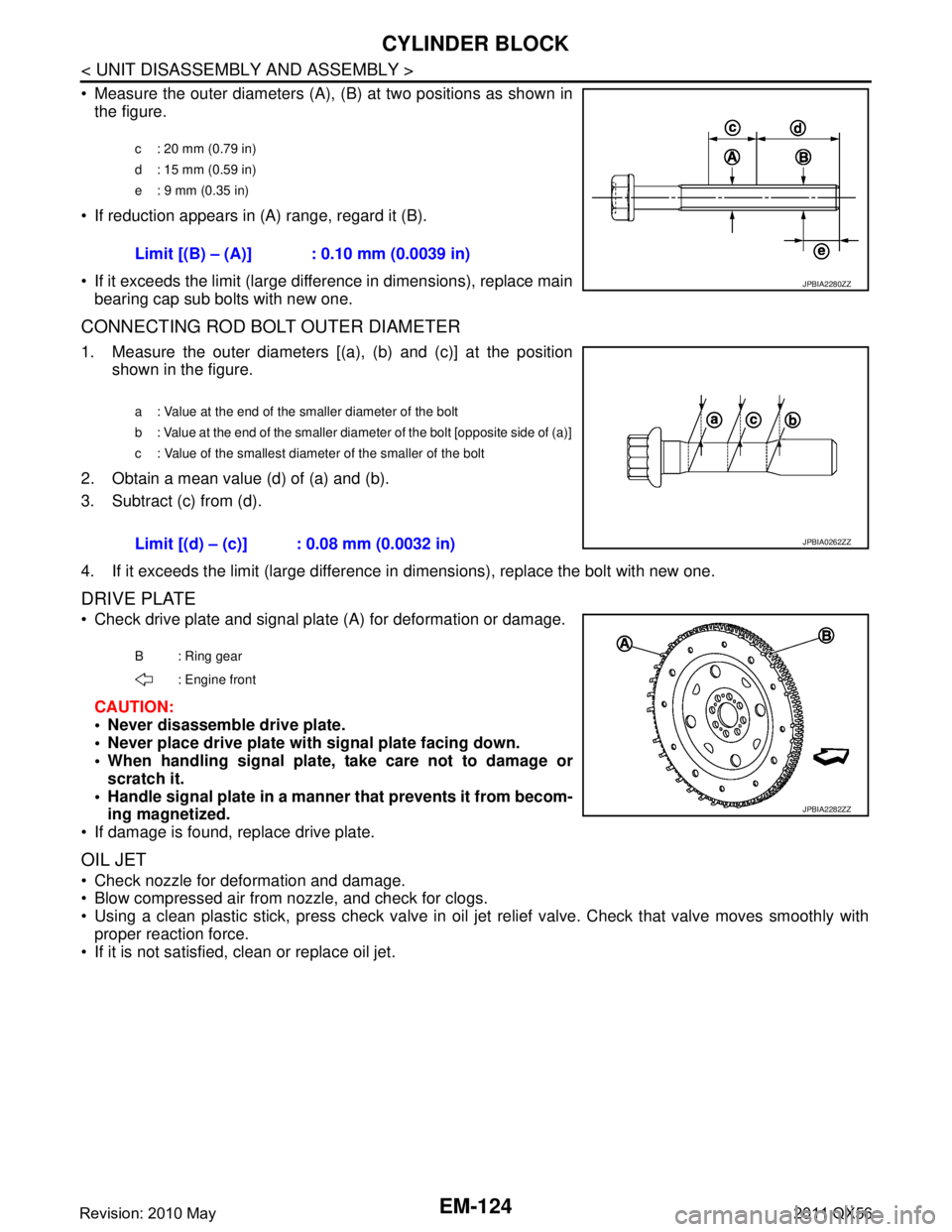
Measure the outer diameters (A), (B) at two positions as shown in
the figure.
If reduction appears in (A) range, regard it (B).
If it exceeds the limit (large difference in dimensions), replace main bearing cap sub bolts with new one.
CONNECTING ROD BOLT OUTER DIAMETER
1. Measure the outer diameters [(a), (b) and (c)] at the position shown in the figure.
2. Obtain a mean value (d) of (a) and (b).
3. Subtract (c) from (d).
4. If it exceeds the limit (large difference in dimensions), replace the bolt with new one.
DRIVE PLATE
Check drive plate and signal plate (A) for deformation or damage.
CAUTION:
Never disassemble drive plate.
Never place drive plate with signal plate facing down.
When handling signal plate, take care not to damage or scratch it.
Handle signal plate in a manner that prevents it from becom-
ing magnetized.
If damage is found, replace drive plate.
OIL JET
Check nozzle for deformation and damage.
Blow compressed air from nozzle, and check for clogs.
Using a clean plastic stick, press check valve in oil je t relief valve. Check that valve moves smoothly with
proper reaction force.
If it is not satisfied, clean or replace oil jet.
c : 20 mm (0.79 in)
d : 15 mm (0.59 in)
e : 9 mm (0.35 in)
Limit [(B) – (A)] : 0.10 mm (0.0039 in)
JPBIA2280ZZ
a : Value at the end of the smaller diameter of the bolt
b : Value at the end of the smaller diameter of the bolt [opposite side of (a)]
c : Value of the smallest diameter of the smaller of the bolt
Limit [(d) – (c)] : 0.08 mm (0.0032 in)JPBIA0262ZZ
B : Ring gear
: Engine front
JPBIA2282ZZ
Revision: 2010 May2011 QX56
Page 2737 of 5598
![INFINITI QX56 2011 Factory Service Manual
DIAGNOSIS SYSTEM (IPDM E/R)EXL-27
< SYSTEM DESCRIPTION > [XENON TYPE]
C
D
E
F
G H
I
J
K
M A
B
EXL
N
O P
DIAGNOSIS SYSTEM (IPDM E/R)
Diagnosis DescriptionINFOID:0000000006368066
AUTO ACTIVE TEST
Descr INFINITI QX56 2011 Factory Service Manual
DIAGNOSIS SYSTEM (IPDM E/R)EXL-27
< SYSTEM DESCRIPTION > [XENON TYPE]
C
D
E
F
G H
I
J
K
M A
B
EXL
N
O P
DIAGNOSIS SYSTEM (IPDM E/R)
Diagnosis DescriptionINFOID:0000000006368066
AUTO ACTIVE TEST
Descr](/img/42/57033/w960_57033-2736.png)
DIAGNOSIS SYSTEM (IPDM E/R)EXL-27
< SYSTEM DESCRIPTION > [XENON TYPE]
C
D
E
F
G H
I
J
K
M A
B
EXL
N
O P
DIAGNOSIS SYSTEM (IPDM E/R)
Diagnosis DescriptionINFOID:0000000006368066
AUTO ACTIVE TEST
Description
In auto active test, the IPDM E/R sends a drive signal to the following systems to check their operation.
Oil pressure warning lamp
Rear window defogger
Front wiper (LO, HI)
Parking lamp
License plate lamp
Tail lamp
Side marker lamp
Front fog lamp
Headlamp (LO, HI)
A/C compressor (magnet clutch)
Operation Procedure
CAUTION:
Never perform auto active test in the following conditions.
Engine is running.
CONSULT-III is connected.
1. Close the hood and lift the wiper arms from the windshield. (Prevent windshield damage due to wiper
operation)
NOTE:
When auto active test is performed with hood opened, sprinkle water on windshield beforehand.
2. Turn the ignition switch OFF.
3. Turn the ignition switch ON, and within 20 seconds, pr ess the driver door switch 10 times. Then turn the
ignition switch OFF.
CAUTION:
Close passenger door.
4. Turn the ignition switch ON within 10 seconds. Af ter that the horn sounds once and the auto active test
starts.
CAUTION:
Engine starts when ignition switch is turned ON while brake pedal is depressed.
5. The oil pressure warning lamp starts blinking when the auto active test starts.
6. After a series of the following operations is repeated 3 times, auto active test is completed.
NOTE:
When auto active test has to be cancelled halfw ay through test, turn the ignition switch OFF.
When auto active test is not activated, door swit ch may be the cause. Check door switch. Refer to DLK-117,
"ComponentFunctionCheck".
Inspection in Auto Active Test
When auto active test is actuated, the following operation sequence is repeated 3 times.
Operation
sequence Inspection location Operation
1 Oil pressure warning lamp Blinks continuously during operation of auto active test
2 Rear window defogger 10 seconds
3 Front wiper LO for 5 seconds → HI for 5 seconds
4 Parking lamp
License plate lamp
Tail lamp
Side marker lamp
Front fog lamp 10 seconds
Revision: 2010 May2011 QX56
Page 2831 of 5598
![INFINITI QX56 2011 Factory Service Manual
HEADLAMP AIMING ADJUSTMENTEXL-121
< PERIODIC MAINTENANCE > [XENON TYPE]
C
D
E
F
G H
I
J
K
M A
B
EXL
N
O P
PERIODIC MAINTENANCE
HEADLAMP AIMING ADJUSTMENT
descriptionINFOID:0000000006213990
preparatio INFINITI QX56 2011 Factory Service Manual
HEADLAMP AIMING ADJUSTMENTEXL-121
< PERIODIC MAINTENANCE > [XENON TYPE]
C
D
E
F
G H
I
J
K
M A
B
EXL
N
O P
PERIODIC MAINTENANCE
HEADLAMP AIMING ADJUSTMENT
descriptionINFOID:0000000006213990
preparatio](/img/42/57033/w960_57033-2830.png)
HEADLAMP AIMING ADJUSTMENTEXL-121
< PERIODIC MAINTENANCE > [XENON TYPE]
C
D
E
F
G H
I
J
K
M A
B
EXL
N
O P
PERIODIC MAINTENANCE
HEADLAMP AIMING ADJUSTMENT
descriptionINFOID:0000000006213990
preparation before adjusting
NOTE:
for details, refer to the regulations in your own country.
perform aiming if the vehicle front body has been repaired and/or the headlamp assembly has been
replaced.
before performing aiming adjustment, check the following. adjust the tire pressure to the specification.
fill with fuel, engine coolant and each oil.
maintain the unloaded vehicle condition. (remove luggage from the passenger compartment and the lug- gage room.)
NOTE:
do not remove the temporary tire, jack and on-vehicle tool.
wipe out dirt on the headlamp.
CAUTION:
never use organic solvent (thinner, gasoline etc.)
ride alone on the driver seat.
aiming adjustment screw
JMLIA1319ZZ
A. Headlamp RH HI /LO (UP/DOWN)
adjustment screw B. Headlamp LH HI/LO (UP/DOWN)
adjustment screw
: Vehicle center
Revision: 2010 May2011 QX56
Page 2833 of 5598
![INFINITI QX56 2011 Factory Service Manual
FRONT FOG LAMP AIMING ADJUSTMENTEXL-123
< PERIODIC MAINTENANCE > [XENON TYPE]
C
D
E
F
G H
I
J
K
M A
B
EXL
N
O P
FRONT FOG LAMP AI MING ADJUSTMENT
DescriptionINFOID:0000000006213992
PREPARATION BEFORE INFINITI QX56 2011 Factory Service Manual
FRONT FOG LAMP AIMING ADJUSTMENTEXL-123
< PERIODIC MAINTENANCE > [XENON TYPE]
C
D
E
F
G H
I
J
K
M A
B
EXL
N
O P
FRONT FOG LAMP AI MING ADJUSTMENT
DescriptionINFOID:0000000006213992
PREPARATION BEFORE](/img/42/57033/w960_57033-2832.png)
FRONT FOG LAMP AIMING ADJUSTMENTEXL-123
< PERIODIC MAINTENANCE > [XENON TYPE]
C
D
E
F
G H
I
J
K
M A
B
EXL
N
O P
FRONT FOG LAMP AI MING ADJUSTMENT
DescriptionINFOID:0000000006213992
PREPARATION BEFORE ADJUSTING
NOTE:
For details, refer to the regulations in your own country.
Perform aiming if the vehicle front body has been repaired and/or the headlamp assembly has been
replaced.
Before performing aiming adjustm ent, check the following. Adjust the tire pressure to the specification.
Fill with fuel, engine coolant and each oil.
Maintain the unloaded vehicle condition. (Remove luggage from the passenger compartment and the trunk
room.)
NOTE:
Do not remove the temporary tire, jack and on-vehicle tool.
Wipe out dirt on the headlamp. CAUTION:
Never use organic solvent (thinner, gasoline etc.)
Ride alone on the driver seat.
AIMING ADJUSTMENT SCREW
Turn the aiming adjusting screw for adjustment.
For the position and direction of the adjusting screw, refer to the figure.
NOTE:
A screwdriver or hexagonal wrench [6 mm (0.24 in)] can be used
for adjustment.
Aiming Adjustment ProcedureINFOID:0000000006213993
1. Place the screen. NOTE:
Stop the vehicle facing the wall.
Place the board on a plain road vertically.
2. Face the vehicle with the screen. Maintain 10 m (32.8 ft) between the front fog lamp center and the
screen.
3. Start the engine. Turn the front fog lamp ON. NOTE:
Shut off the headlamp light with the board to pr event from illuminating the adjustment screen.
CAUTION:
Never cover the lens surface with a tape etc. The lens is made of resin.
4. Adjust the cutoff line height (A) with the aiming adjus tment screw so that the distance (X) between the hor-
izontal center line of front fog lamp (H) and (A) becomes 200 mm (7.87 in).
A: UP
B: DOWN
JPLIA0915ZZ
Revision: 2010 May2011 QX56
Page 2945 of 5598
PRECAUTIONSFSU-3
< PRECAUTION >
C
DF
G H
I
J
K L
M A
B
FSU
N
O P
5. When the repair work is completed, re-connect both battery cables. With the brake pedal released, turn
the push-button ignition switch from ACC position to ON position, then to LOCK position. (The steering
wheel will lock when the push-button ignition switch is turned to LOCK position.)
6. Perform self-diagnosis check of a ll control units using CONSULT-III.
Precaution for Procedure without Cowl Top CoverINFOID:0000000006271994
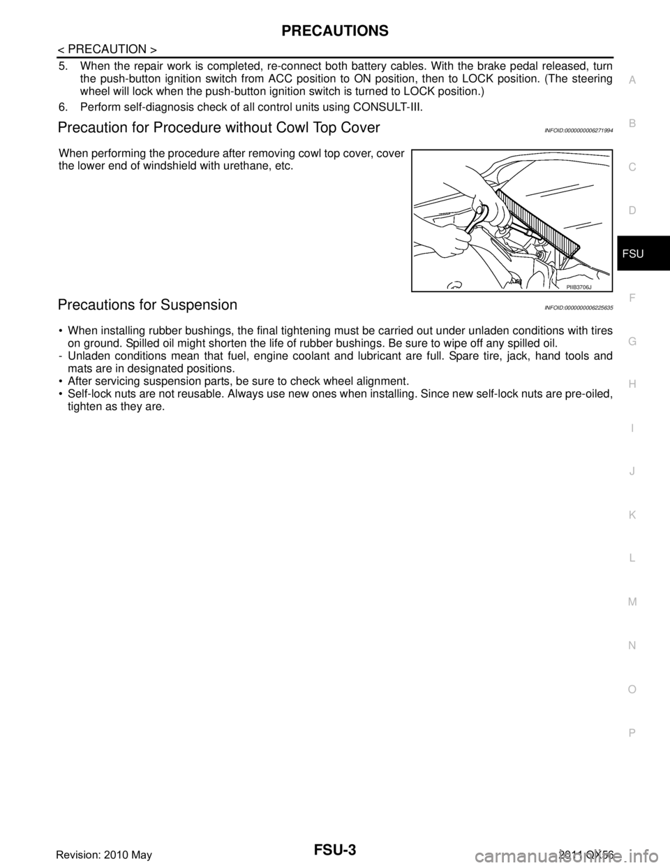
When performing the procedure after removing cowl top cover, cover
the lower end of windshield with urethane, etc.
Precautions for SuspensionINFOID:0000000006225635
When installing rubber bushings, the final tightening mu st be carried out under unladen conditions with tires
on ground. Spilled oil might shorten the life of rubb er bushings. Be sure to wipe off any spilled oil.
- Unladen conditions mean that fuel, engine coolant and l ubricant are full. Spare tire, jack, hand tools and
mats are in designated positions.
After servicing suspension parts, be sure to check wheel alignment.
Self-lock nuts are not reusable. Always use new ones w hen installing. Since new self-lock nuts are pre-oiled,
tighten as they are.
PIIB3706J
Revision: 2010 May2011 QX56
Page 2965 of 5598
GI-1
GENERAL INFORMATION
C
DE
F
G H
I
J
K L
M B
GI
SECTION GI
N
O P
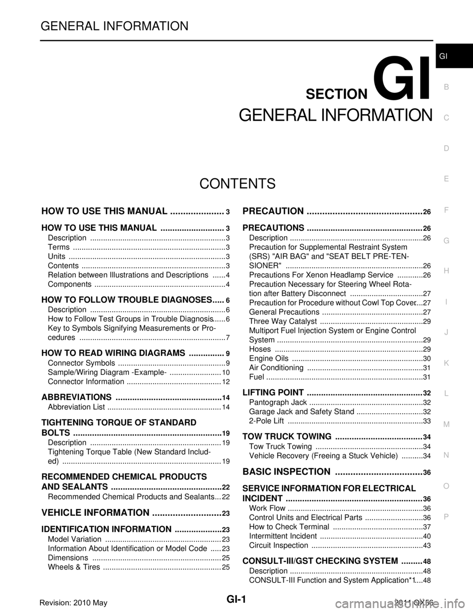
CONTENTS
GENERAL INFORMATION
HOW TO USE THIS MANU AL ......................3
HOW TO USE THIS MANUAL ....................... .....3
Description .......................................................... ......3
Terms ........................................................................3
Units ..........................................................................3
Contents ....................................................................3
Relation between Illustrations and Descriptions .......4
Components ..............................................................4
HOW TO FOLLOW TROUBLE DIAGNOSES .....6
Description ................................................................6
How to Follow Test Groups in Trouble Diagnosis ......6
Key to Symbols Signifying Measurements or Pro-
cedures ............................................................... ......
7
HOW TO READ WIRING DIAGRAMS ................9
Connector Symbols ............................................. ......9
Sample/Wiring Diagram -Example- .........................10
Connector Information .............................................12
ABBREVIATIONS .......................................... ....14
Abbreviation List .................................................. ....14
TIGHTENING TORQUE OF STANDARD
BOLTS ................................................................
19
Description .......................................................... ....19
Tightening Torque Table (New Standard Includ-
ed) ...........................................................................
19
RECOMMENDED CHEMICAL PRODUCTS
AND SEALANTS ................................................
22
Recommended Chemical Products and Sealants ....22
VEHICLE INFORMATION ............................23
IDENTIFICATION INFORMATION ................. ....23
Model Variation ................................................... ....23
Information About Identification or Model Code ......23
Dimensions .............................................................25
Wheels & Tires ........................................................25
PRECAUTION ..............................................26
PRECAUTIONS .................................................26
Description ........................................................... ....26
Precaution for Supplemental Restraint System
(SRS) "AIR BAG" and "SEAT BELT PRE-TEN-
SIONER" .................................................................
26
Precautions For Xenon Headlamp Service .............26
Precaution Necessary for Steering Wheel Rota-
tion after Battery Disconnect ...................................
27
Precaution for Procedure without Cowl Top Cover ....27
General Precautions ................................................27
Three Way Catalyst .................................................29
Multiport Fuel Injection System or Engine Control
System .....................................................................
29
Hoses ......................................................................29
Engine Oils ..............................................................30
Air Conditioning .......................................................31
Fuel ..........................................................................31
LIFTING POINT .................................................32
Pantograph Jack ......................................................32
Garage Jack and Safety Stand ................................32
2-Pole Lift ................................................................33
TOW TRUCK TOWING .....................................34
Tow Truck Towing ...................................................34
Vehicle Recovery (Freeing a Stuck Vehicle) ...........34
BASIC INSPECTION ...................................36
SERVICE INFORMATION FOR ELECTRICAL
INCIDENT ..........................................................
36
Work Flow ............................................................ ....36
Control Units and Electrical Parts ............................36
How to Check Terminal ...........................................37
Intermittent Incident .................................................40
Circuit Inspection .....................................................43
CONSULT-III/GST CHECKING SYSTEM .........48
Description ...............................................................48
CONSULT-III Function and System Application*1 ....48
Revision: 2010 May2011 QX56
Page 2979 of 5598
ABBREVIATIONSGI-15
< HOW TO USE THIS MANUAL >
C
DE
F
G H
I
J
K L
M B
GI
N
O P
E
F
G
H
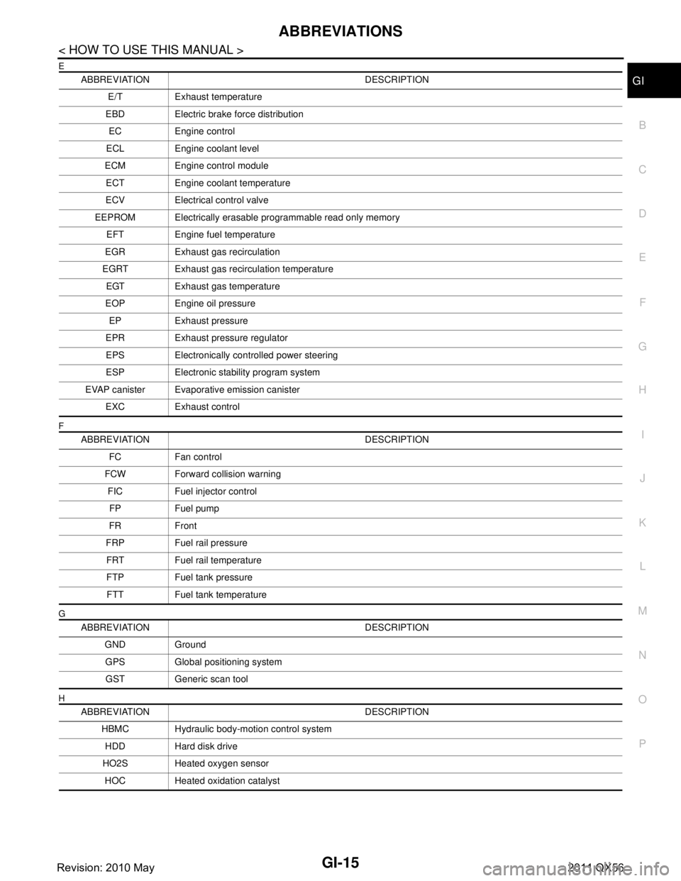
ABBREVIATION DESCRIPTION E/T Exhaust temperature
EBD Electric brake force distribution EC Engine control
ECL Engine coolant level
ECM Engine control module ECT Engine coolant temperature
ECV Electrical control valve
EEPROM Electrically erasable programmable read only memory EFT Engine fuel temperature
EGR Exhaust gas recirculation
EGRT Exhaust gas recirculation temperature EGT Exhaust gas temperature
EOP Engine oil pressure EP Exhaust pressure
EPR Exhaust pressure regulator EPS Electronically controlled power steering
ESP Electronic stability program system
EVAP canister Evaporative emission canister EXC Exhaust control
ABBREVIATION DESCRIPTION FC Fan control
FCW Forward collision warning FIC Fuel injector controlFP Fuel pump
FR Front
FRP Fuel rail pressure FRT Fuel rail temperature
FTP Fuel tank pressure FTT Fuel tank temperature
ABBREVIATION DESCRIPTION GND GroundGPS Global positioning systemGST Generic scan tool
ABBREVIATION DESCRIPTION HBMC Hydraulic body-motion control systemHDD Hard disk drive
HO2S Heated oxygen sensor HOC Heated oxidation catalyst
Revision: 2010 May2011 QX56
Page 2990 of 5598
GI-26
< PRECAUTION >
PRECAUTIONS
PRECAUTION
PRECAUTIONS
DescriptionINFOID:0000000006280865
Observe the following precautions to ensure safe and proper servicing. These precautions are not
described in each individual section.
Precaution for Supplemental Restraint S ystem (SRS) "AIR BAG" and "SEAT BELT
PRE-TENSIONER"
INFOID:0000000006280866
The Supplemental Restraint System such as “A IR BAG” and “SEAT BELT PRE-TENSIONER”, used along
with a front seat belt, helps to reduce the risk or severi ty of injury to the driver and front passenger for certain
types of collision. This system includes seat belt switch inputs and dual stage front air bag modules. The SRS
system uses the seat belt switches to determine the front air bag deployment, and may only deploy one front
air bag, depending on the severity of a collision and w hether the front occupants are belted or unbelted.
Information necessary to service the system safely is included in the “SRS AIR BAG” and “SEAT BELT” of this
Service Manual.
WARNING:
To avoid rendering the SRS inopera tive, which could increase the risk of personal injury or death in
the event of a collision that would result in air bag inflation, all maintenance must be performed by
an authorized NISS AN/INFINITI dealer.
Improper maintenance, including in correct removal and installation of the SRS, can lead to personal
injury caused by unintent ional activation of the system. For re moval of Spiral Cable and Air Bag
Module, see the “SRS AIR BAG”.
Do not use electrical test equipmen t on any circuit related to the SRS unless instructed to in this
Service Manual. SRS wiring harnesses can be identi fied by yellow and/or orange harnesses or har-
ness connectors.
PRECAUTIONS WHEN USING POWER TOOLS (AIR OR ELECTRIC) AND HAMMERS
WARNING:
When working near the Air Bag Diagnosis Sensor Unit or other Air Bag System sensors with the
ignition ON or engine running, DO NOT use air or electric power tools or strike near the sensor(s)
with a hammer. Heavy vibration could activate the sensor(s) and deploy the air bag(s), possibly
causing serious injury.
When using air or electric power tools or hammers , always switch the ignition OFF, disconnect the
battery, and wait at least 3 minu tes before performing any service.
Precautions For Xenon Headlamp ServiceINFOID:0000000006280867
WARNING:
Comply with the following warnings to prevent any serious accident.
Disconnect the battery cable (negative terminal) or the power supply fuse before installing, remov-
ing, or touching the xenon headlamp (bulb included). The xenon headlamp contains high-voltage
generated parts.
Never work with wet hands.
Check the xenon headlamp ON-OFF status after assembling it to the vehicle. Never turn the xenon
headlamp ON in other conditions. Connect th e power supply to the vehicle-side connector.
(Turning it ON outside the lamp case m ay cause fire or visual impairments.)
Never touch the bulb glass immediately after turning it OFF. It is extremely hot.
CAUTION:
Comply with the following cautions to prevent any error and malfunction.
Install the xenon bulb securely. (Ins ufficient bulb socket installation may melt the bulb, the connec-
tor, the housing, etc. by high-v oltage leakage or corona discharge.)
Never perform HID circuit in spection with a tester.
Never touch the xenon bulb glass with ha nds. Never put oil and grease on it.
Dispose of the used xenon bulb after packing it in thick vinyl without breaking it.
Never wipe out dirt and cont amination with organic solven t (thinner, gasoline, etc.).
Revision: 2010 May2011 QX56
Page 2992 of 5598
GI-28
< PRECAUTION >
PRECAUTIONS
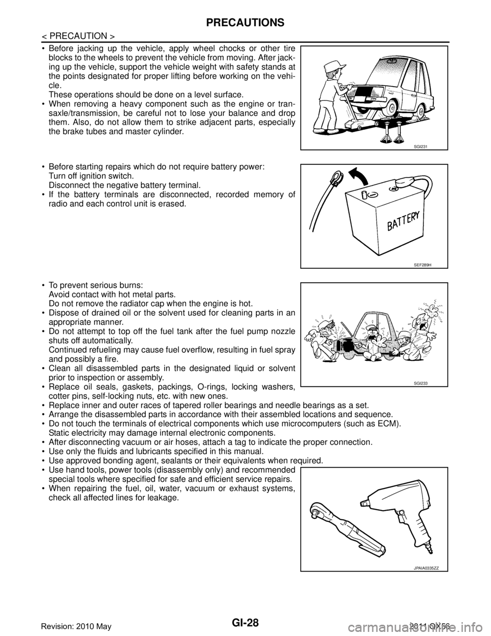
Before jacking up the vehicle, apply wheel chocks or other tireblocks to the wheels to prevent t he vehicle from moving. After jack-
ing up the vehicle, support the vehicle weight with safety stands at
the points designated for proper lifting before working on the vehi-
cle.
These operations should be done on a level surface.
When removing a heavy component such as the engine or tran- saxle/transmission, be careful not to lose your balance and drop
them. Also, do not allow them to strike adjacent parts, especially
the brake tubes and master cylinder.
Before starting repairs which do not require battery power: Turn off ignition switch.
Disconnect the negative battery terminal.
If the battery terminals are disconnected, recorded memory of
radio and each control unit is erased.
To prevent serious burns: Avoid contact with hot metal parts.
Do not remove the radiator cap when the engine is hot.
Dispose of drained oil or the solvent used for cleaning parts in an appropriate manner.
Do not attempt to top off the fuel tank after the fuel pump nozzle
shuts off automatically.
Continued refueling may cause fuel overflow, resulting in fuel spray
and possibly a fire.
Clean all disassembled parts in the designated liquid or solvent prior to inspection or assembly.
Replace oil seals, gaskets, packings, O-rings, locking washers,
cotter pins, self-locking nuts, etc. with new ones.
Replace inner and outer races of tapered roller bearings and needle bearings as a set.
Arrange the disassembled parts in accordance with their assembled locations and sequence.
Do not touch the terminals of electrical com ponents which use microcomputers (such as ECM).
Static electricity may damage internal electronic components.
After disconnecting vacuum or air hoses, atta ch a tag to indicate the proper connection.
Use only the fluids and lubricants specified in this manual.
Use approved bonding agent, sealants or their equivalents when required.
Use hand tools, power tools (disassembly only) and recommended special tools where specified for safe and efficient service repairs.
When repairing the fuel, oil, water, vacuum or exhaust systems, check all affected lines for leakage.
SGI231
SEF289H
SGI233
JPAIA0335ZZ
Revision: 2010 May2011 QX56