engine oil INFINITI QX56 2011 Factory Owners Manual
[x] Cancel search | Manufacturer: INFINITI, Model Year: 2011, Model line: QX56, Model: INFINITI QX56 2011Pages: 5598, PDF Size: 94.53 MB
Page 2622 of 5598
EM-60
< REMOVAL AND INSTALLATION >
OIL PAN (UPPER)
3. Install oil pan (lower). Refer to EM-55, "Removal and Installation".
4. Install in the reverse order of removal. NOTE:
At least 30 minutes after oil pan is installed, pour engine oil.
InspectionINFOID:0000000006289564
INSPECTION AFTER DISASSEMBLY
Clean oil strainer if any object is attached.
INSPECTION AFTER ASSEMBLY
1. Check the engine oil level and adjust engine oil. Refer to LU-9, "Inspection".
2. Start engine, and check there is no leakage of engine oil.
3. Stop engine and wait for 15 minutes.
4. Check the engine oil level again. Refer to LU-9, "
Inspection".
Revision: 2010 May2011 QX56
Page 2624 of 5598
EM-62
< REMOVAL AND INSTALLATION >
TIMING CHAIN
Removal and Installation
INFOID:0000000006289566
REMOVAL
1. Release fuel pressure. Refer to EC-153, "Work Procedure".
2. Drain engine coolant from radiator. Refer to CO-8, "
Draining".
3. Remove fan shroud (lower). Refer to CO-13, "
Exploded View".
4. Remove fan bracket. Refer to CO-16, "
Exploded View".
5. Remove drive belt auto-tensioner. Refer to EM-26, "
Exploded View".
6. Remove oil level gauge and oil level gauge guide. Refer to EM-57, "
Exploded View".
7. Move power steering oil pump to the posit ion without the hindrance for work. Refer to ST-48, "
Exploded
View".
8. Remove alternator, alternator bracket and alternator stay. Refer to CHG-25, "
Exploded View".
9. Move power steering reservoir tank to the position without the hindrance for work, and then remove Res- ervoir tank bracket. Refer to ST-54, "
Exploded View".
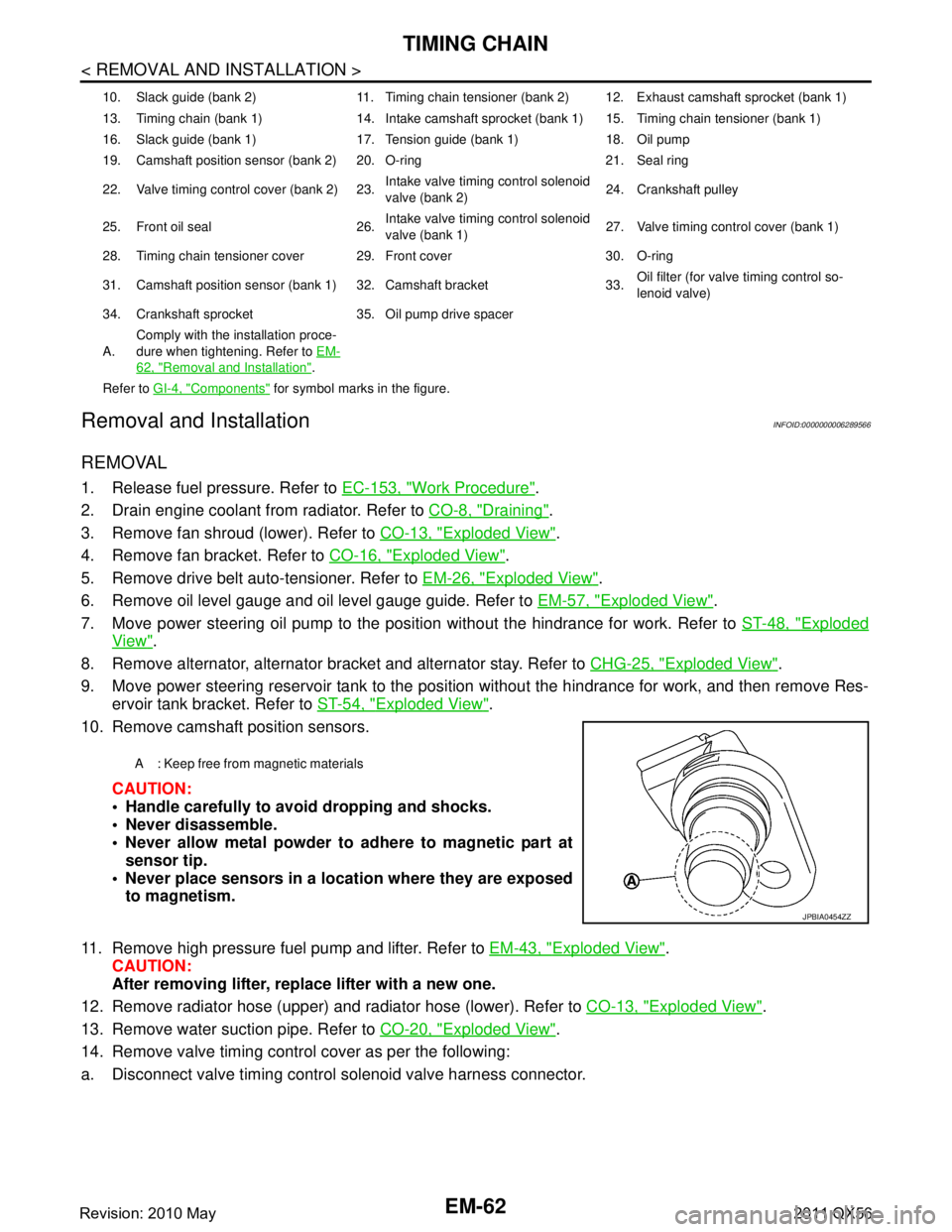
10. Remove camshaft position sensors.
CAUTION:
Handle carefully to avoid dropping and shocks.
Never disassemble.
Never allow metal powder to adhere to magnetic part atsensor tip.
Never place sensors in a lo cation where they are exposed
to magnetism.
11. Remove high pressure fuel pump and lifter. Refer to EM-43, "
Exploded View".
CAUTION:
After removing lifter, replace lifter with a new one.
12. Remove radiator hose (upper) and radiator hose (lower). Refer to CO-13, "
Exploded View".
13. Remove water suction pipe. Refer to CO-20, "
Exploded View".
14. Remove valve timing control cover as per the following:
a. Disconnect valve timing control solenoid valve harness connector.
10. Slack guide (bank 2) 11. Timing chain tensioner (bank 2) 12. Exhaust camshaft sprocket (bank 1)
13. Timing chain (bank 1) 14. Intake camshaft sprocket (bank 1) 15. Timing chain tensioner (bank 1)
16. Slack guide (bank 1) 17. Tension guide (bank 1) 18. Oil pump
19. Camshaft position sensor (bank 2) 20. O-ring 21. Seal ring
22. Valve timing control cover (bank 2) 23. Intake valve timing control solenoid
valve (bank 2)24. Crankshaft pulley
25. Front oil seal 26. Intake valve timing control solenoid
valve (bank 1)27. Valve timing control cover (bank 1)
28. Timing chain tensioner cover 29. Front cover 30. O-ring
31. Camshaft position sensor (bank 1) 32. Camshaft bracket 33. Oil filter (for valve timing control so-
lenoid valve)
34. Crankshaft sprocket 35. Oil pump drive spacer
A. Comply with the installation proce-
dure when tightening. Refer to
EM-
62, "Removal and Installation".
Refer to GI-4, "
Components" for symbol marks in the figure.
A : Keep free from magnetic materials
JPBIA0454ZZ
Revision: 2010 May2011 QX56
Page 2634 of 5598
EM-72
< REMOVAL AND INSTALLATION >
TIMING CHAIN
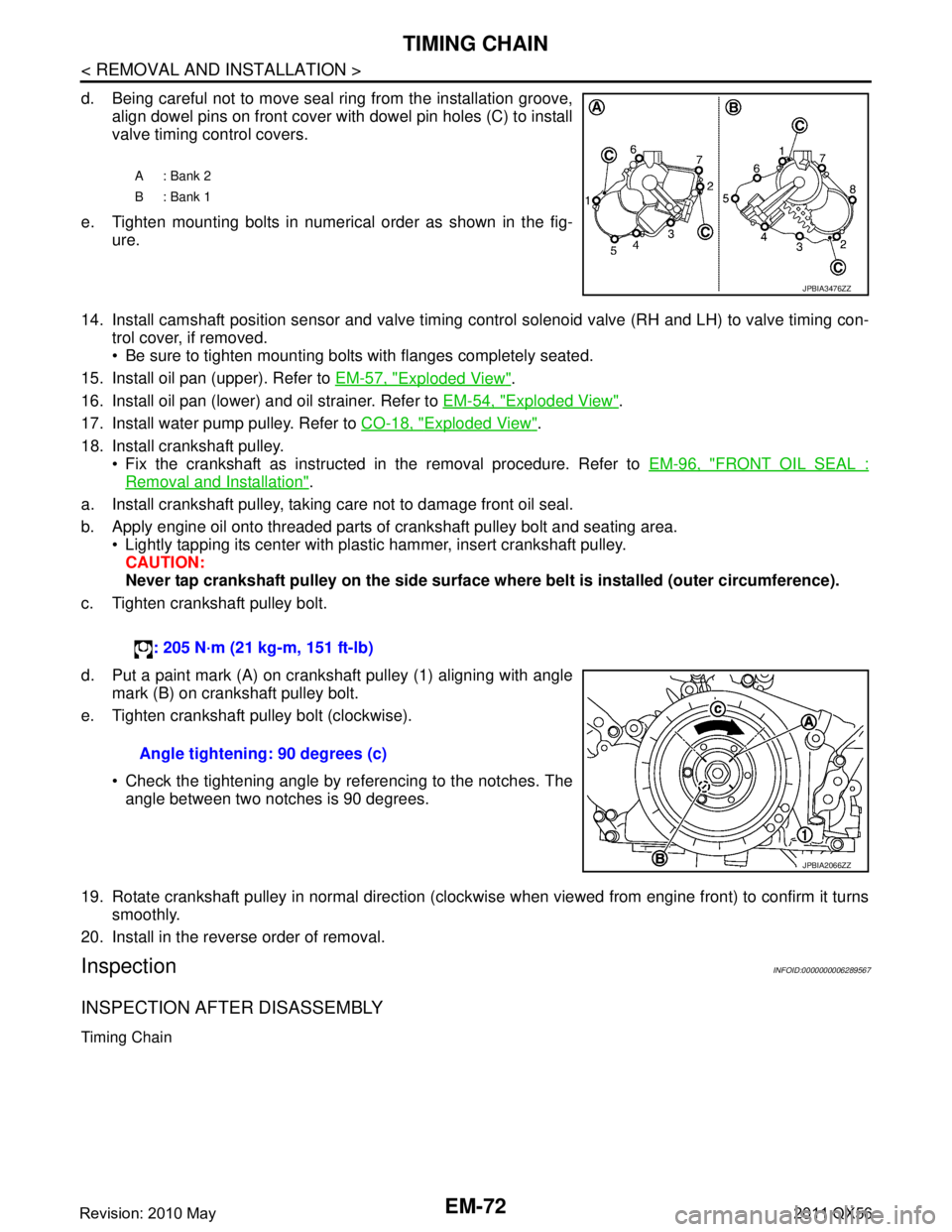
d. Being careful not to move seal ring from the installation groove,align dowel pins on front cover with dowel pin holes (C) to install
valve timing control covers.
e. Tighten mounting bolts in numerical order as shown in the fig- ure.
14. Install camshaft position sensor and valve timing c ontrol solenoid valve (RH and LH) to valve timing con-
trol cover, if removed.
Be sure to tighten mounting bolts with flanges completely seated.
15. Install oil pan (upper). Refer to EM-57, "
Exploded View".
16. Install oil pan (lower) and oil strainer. Refer to EM-54, "
Exploded View".
17. Install water pump pulley. Refer to CO-18, "
Exploded View".
18. Install crankshaft pulley. Fix the crankshaft as instructed in the removal procedure. Refer to EM-96, "
FRONT OIL SEAL :
Removal and Installation".
a. Install crankshaft pulley, taking care not to damage front oil seal.
b. Apply engine oil onto threaded parts of crankshaft pulley bolt and seating area. Lightly tapping its center with plastic hammer, insert crankshaft pulley.
CAUTION:
Never tap crankshaft pulley on the side surface wh ere belt is installed (outer circumference).
c. Tighten crankshaft pulley bolt.
d. Put a paint mark (A) on crankshaft pulley (1) aligning with angle mark (B) on crankshaft pulley bolt.
e. Tighten crankshaft pulley bolt (clockwise).
Check the tightening angle by referencing to the notches. Theangle between two notches is 90 degrees.
19. Rotate crankshaft pulley in normal direction (clockwise when viewed from engine front) to confirm it turns smoothly.
20. Install in the reverse order of removal.
InspectionINFOID:0000000006289567
INSPECTION AFTER DISASSEMBLY
Timing Chain
A: Bank 2
B: Bank 1
JPBIA3476ZZ
: 205 N·m (21 kg-m, 151 ft-lb)
Angle tightening: 90 degrees (c)
JPBIA2066ZZ
Revision: 2010 May2011 QX56
Page 2635 of 5598
TIMING CHAINEM-73
< REMOVAL AND INSTALLATION >
C
DE
F
G H
I
J
K L
M A
EM
NP
O
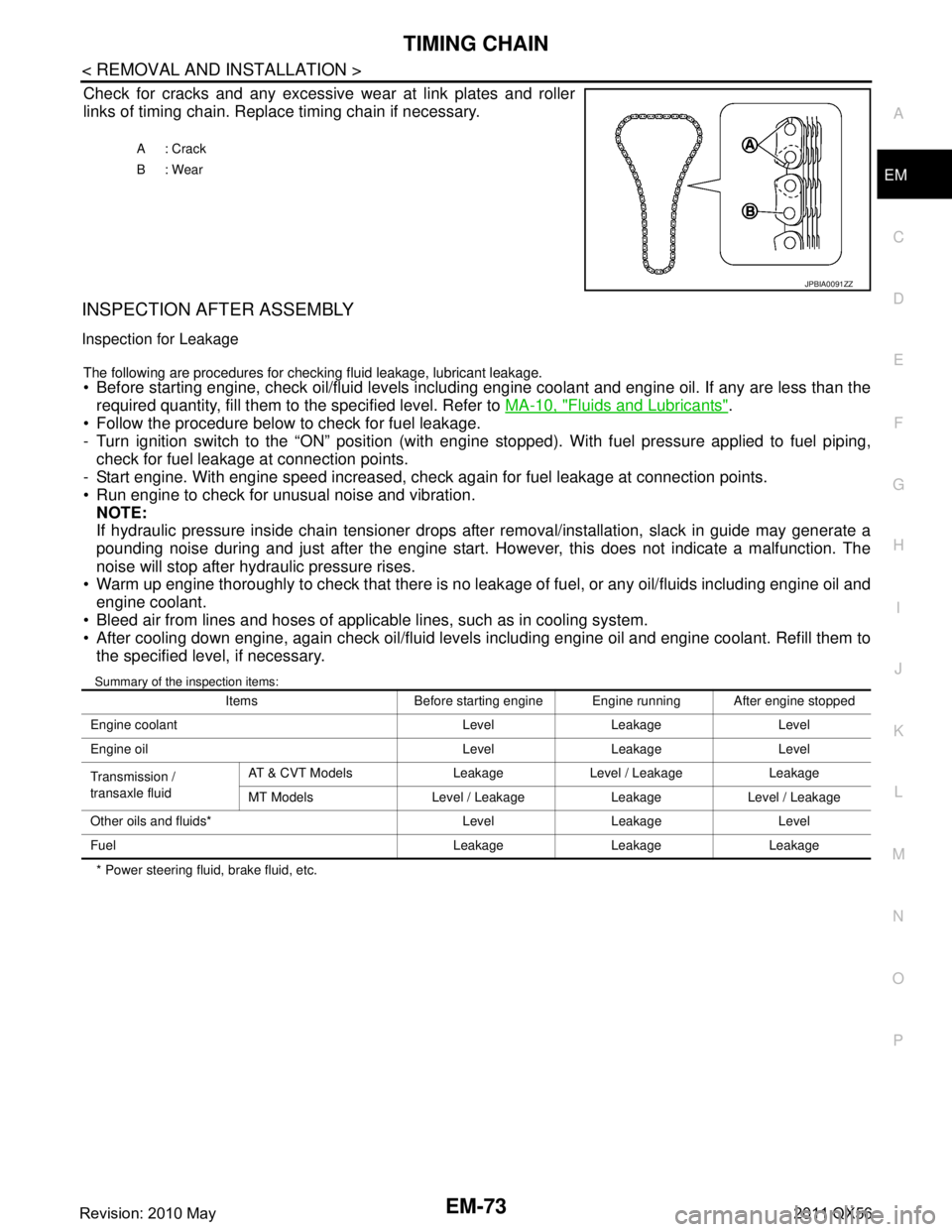
Check for cracks and any excessive
wear at link plates and roller
links of timing chain. Replace timing chain if necessary.
INSPECTION AFTER ASSEMBLY
Inspection for Leakage
The following are procedures for chec king fluid leakage, lubricant leakage. Before starting engine, check oil/fluid levels including engine coolant and engine oil. If any are less than the
required quantity, fill them to the specified level. Refer to MA-10, "
Fluids and Lubricants".
Follow the procedure below to check for fuel leakage.
- Turn ignition switch to the “ON” position (with engi ne stopped). With fuel pressure applied to fuel piping,
check for fuel leakage at connection points.
- Start engine. With engine speed increased, check again for fuel leakage at connection points.
Run engine to check for unusual noise and vibration.
NOTE:
If hydraulic pressure inside chain tensioner drops after removal/installation, slack in guide may generate a
pounding noise during and just after the engine start. However, this does not indicate a malfunction. The
noise will stop after hydraulic pressure rises.
Warm up engine thoroughly to check that there is no leak age of fuel, or any oil/fluids including engine oil and
engine coolant.
Bleed air from lines and hoses of applicable lines, such as in cooling system.
After cooling down engine, again check oil/fluid levels including engine oil and engine coolant. Refill them to the specified level, if necessary.
Summary of the inspection items:
* Power steering fluid, brake fluid, etc. A: Crack
B: Wear
JPBIA0091ZZ
Items Before starting engine Engine running After engine stopped
Engine coolant Level Leakage Level
Engine oil Level Leakage Level
Transmission /
transaxle fluid AT & CVT Models Leakage Level / Leakage Leakage
MT Models Level / Leakage Leakage Level / Leakage
Other oils and fluids* Level Leakage Level
Fuel Leakage Leakage Leakage
Revision: 2010 May2011 QX56
Page 2646 of 5598
EM-84
< REMOVAL AND INSTALLATION >
CAMSHAFT
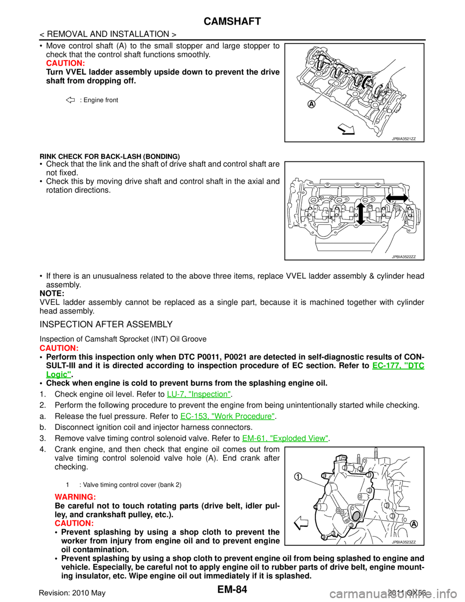
Move control shaft (A) to the small stopper and large stopper tocheck that the control shaft functions smoothly.
CAUTION:
Turn VVEL ladder assembly upside down to prevent the drive
shaft from dropping off.
RINK CHECK FOR BACK-LASH (BONDING) Check that the link and the shaft of drive shaft and control shaft are
not fixed.
Check this by moving drive shaft and control shaft in the axial and
rotation directions.
If there is an unusualness related to the above three items, replace VVEL ladder assembly & cylinder head
assembly.
NOTE:
VVEL ladder assembly cannot be replaced as a singl e part, because it is machined together with cylinder
head assembly.
INSPECTION AFTER ASSEMBLY
Inspection of Camshaft Sprocket (INT) Oil Groove
CAUTION:
Perform this inspection only when DTC P0011, P 0021 are detected in self-diagnostic results of CON-
SULT-III and it is directed according to inspection procedure of EC section. Refer to EC-177, "
DTC
Logic".
Check when engine is cold to prevent burns from the splashing engine oil.
1. Check engine oil level. Refer to LU-7, "
Inspection".
2. Perform the following procedure to prevent the engine from being unintentionally started while checking.
a. Release the fuel pressure. Refer to EC-153, "
Work Procedure".
b. Disconnect ignition coil and injector harness connectors.
3. Remove valve timing control solenoid valve. Refer to EM-61, "
Exploded View".
4. Crank engine, and then check that engine oil comes out from valve timing control solenoid valve hole (A). End crank after
checking.
WARNING:
Be careful not to touch rotati ng parts (drive belt, idler pul-
ley, and crankshaft pulley, etc.).
CAUTION:
Prevent splashing by using a shop cloth to prevent the worker from injury from en gine oil and to prevent engine
oil contamination.
Prevent splashing by using a shop cloth to prevent engine oil from being splashed to engine and
vehicle. Especially, be careful not to apply engine oil to rubber parts of drive belt, engine mount-
ing insulator, etc. Wipe engine oil out immediately if it is splashed.
: Engine front
JPBIA3521ZZ
JPBIA3522ZZ
1 : Valve timing control cover (bank 2)
JPBIA3523ZZ
Revision: 2010 May2011 QX56
Page 2647 of 5598
CAMSHAFTEM-85
< REMOVAL AND INSTALLATION >
C
DE
F
G H
I
J
K L
M A
EM
NP
O
5. Perform the following inspection if engine oil does not
come out from valve timing control solenoid valve
oil hole of the valve timing control cover.
Remove oil filter, and then clean it. Refer to EM-61, "
Exploded View".
Clean oil groove between oil strainer and valve timing control solenoid valve. Refer to LU-5, "
Engine
Lubrication System" and LU-6, "Engine Lubrication System Schematic".
6. Remove components between valve timing control solenoid valve and camshaft sprocket, and then check each oil groove for clogging.
Clean oil groove if necessary. Refer to LU-5, "
Engine Lubrication System" and LU-6, "Engine Lubrica-
tion System Schematic".
7. After inspection, install removed parts in the reverse order.
Inspection for Leakage
The following are procedures for chec king fluid leakage, lubricant leakage.
Before starting engine, check oil/fluid levels including engine coolant and engine oil. If any are less than the
required quantity, fill them to the specified level. Refer to MA-10, "
Fluids and Lubricants".
Follow the procedure below to check for fuel leakage.
- Turn ignition switch to the “ON” position (with engi ne stopped). With fuel pressure applied to fuel piping,
check for fuel leakage at connection points.
- Start engine. With engine speed increased, check again for fuel leakage at connection points.
Run engine to check for unusual noise and vibration. NOTE:
If hydraulic pressure inside chain tensioner drops after removal/installation, slack in guide may generate a
pounding noise during and just after the engine start. However, this does not indicate a malfunction. The
noise will stop after hydraulic pressure rises.
Warm up engine thoroughly to check that there is no leak age of fuel, or any oil/fluids including engine oil and
engine coolant.
Bleed air from lines and hoses of applicable lines, such as in cooling system.
After cooling down engine, again check oil/fluid levels including engine oil and engine coolant. Refill them to
the specified level, if necessary.
Summary of the inspection items:
* Power steering fluid, brake fluid, etc. Items Before starting engine Engine running After engine stopped
Engine coolant Level Leakage Level
Engine oil Level Leakage Level
Transmission /
transaxle fluid AT & CVT Models Leakage Level / Leakage Leakage
MT Models Level / Leakage Leakage Level / Leakage
Other oils and fluids* Level Leakage Level
Fuel Leakage Leakage Leakage
Revision: 2010 May2011 QX56
Page 2648 of 5598

EM-86
< REMOVAL AND INSTALLATION >
CYLINDER HEAD
CYLINDER HEAD
Exploded ViewINFOID:0000000006289571
CAUTION:
A high degree of precision is required for a valve on the intake side. Never remove the valve related
parts unless necessary.
1. Valve lifter (EXH) 2. Valve collet (EXH) 3. Valve spring retainer (EXH)
4. Valve oil seal (EXH) 5. Valve spring (with valve spring seat)
(EXH)6. Valve guide (EXH)
7. Spark plug 8. Valve lifter (INT) 9. Valve collet (INT)
10. Valve spring retainer (INT) 11. Valve oil seal (INT) 12. Valve spring (with valve spring seat)
(INT)
13. Cylinder head bolt 14. Cylinder head (bank 2) 15. Valve seat (EXH)
16. Valve (EXH) 17. Cylinder head gasket (bank 2) 18. Oil filter (for VVEL ladder assembly)
19. Cylinder block 20. Valve (INT) 21. Valve seat (INT)
22. Cylinder head gasket (bank 1) 23. Cylinder head (bank 1) 24. Engine coolant temperature sensor
A. Comply with the installation proce-
dure when tightening. Refer to
EM-
87, "Removal and Installation".
Refer to GI-4, "
Components" for symbol marks in the figure.
JPBIA3524GB
Revision: 2010 May2011 QX56
Page 2649 of 5598

CYLINDER HEADEM-87
< REMOVAL AND INSTALLATION >
C
DE
F
G H
I
J
K L
M A
EM
NP
O
NOTE:
As for replacement of parts on the intake side as
shown in the exploded view, replace VVEL ladder assem-
bly & cylinder head assembly. (Only valve oil seals are replaceable as a single part.)
VVEL ladder assembly cannot be replaced as a singl e part, because it is machined together with cylinder
head assembly.
Removal and InstallationINFOID:0000000006289572
REMOVAL
1. Remove the following parts: Rocker cover and spark plug: Refer to EM-33, "
Exploded View".
Intake manifold: Refer to EM-30, "
Exploded View".
Exhaust manifold: Refer to EM-40, "
Exploded View".
Water inlet and thermostat housing: Refer to CO-20, "
Exploded View".
Water pipe and heater pipe: Refer to CO-20, "
Exploded View".
Timing chain: Refer to EM-61, "
Exploded View".
Camshaft (EXH) and VVEL ladder assembly: Refer to EM-74, "
Exploded View".
2. Remove cylinder head. Loosen mounting bolts in reverse order as shown in the figure.
Use TORX socket and power tool.
3. Remove cylinder head gaskets.
4. Remove oil filter (for VVEL ladder asse mbly) from cylinder block, if necessary.
5. Remove valve lifter. Identify installation positions, and store them without mixing them up.
INSTALLATION
1. Install oil filter (for VVEL l adder assembly) (1) in the direction
shown in the figure, if removed.
Check that the oil filter does not protrude from the upper sur-
face of cylinder block (2) after installation.
A: Bank 2
B: Bank 1
: Engine front
JPBIA2145ZZ
JPBIA2129ZZ
Revision: 2010 May2011 QX56
Page 2650 of 5598

EM-88
< REMOVAL AND INSTALLATION >
CYLINDER HEAD
2. Install new cylinder head gaskets.
3. Install cylinder head as per the following: CAUTION:
If cylinder head bolts are re-used, check their ou ter diameters before installation. Refer to EM-92,
"Inspection".
Before installing cylinder head, inspect cylinder head distortion. Refer to EM-92, "
Inspection".
Tighten cylinder head bolts in numerical order as shown in fig- ure.
Use TORX socket.
a. Apply new engine oil to threads and seat surfaces of cylinder head bolts.
b. Tighten all cylinder head bolts.
c. Tighten all cylinder head bolts (clockwise).
d. Completely loosen all cylinder head bolts.
CAUTION:
In step “d”, loosen bolts in the reverse order of that indi-
cated in the figure.
e. Tighten all cylinder head bolts.
f. Tighten all cylinder head bolts (clockwise).
g. Tighten all cylinder head bolts again (clockwise).
CAUTION:
Check the tightening angle us ing the angle wrench [SST:
KV10112100 (BT8653-A)] (A). Never make judgment by
visual inspection.
Check tightening angle indicated on the angle wrench indica- tor plate.
4. Install valve lifter. Install it in the original position.
5. Install in the reverse order of removal.
A: Bank 2
B: Bank 1
: Engine front
: 40.0 N·m (4.1 kg-m, 30 ft-lb)
Angle tightening: 75 degrees : 0 N·m (0 kg-m, 0 ft-lb)
: 40.0 N·m (4.1 kg-m, 30 ft-lb)
JPBIA2145ZZ
Angle tightening: 90 degrees
Angle tightening: 90 degrees
JPBIA0175ZZ
Revision: 2010 May2011 QX56
Page 2654 of 5598
![INFINITI QX56 2011 Factory Owners Manual
EM-92
< REMOVAL AND INSTALLATION >
CYLINDER HEAD
a. Apply new engine oil on new valve oil seal joint and seal lip.
b. Using the valve oil seal drift [SST: KV10115600 (J-38958)] (A),press fit valve se INFINITI QX56 2011 Factory Owners Manual
EM-92
< REMOVAL AND INSTALLATION >
CYLINDER HEAD
a. Apply new engine oil on new valve oil seal joint and seal lip.
b. Using the valve oil seal drift [SST: KV10115600 (J-38958)] (A),press fit valve se](/img/42/57033/w960_57033-2653.png)
EM-92
< REMOVAL AND INSTALLATION >
CYLINDER HEAD
a. Apply new engine oil on new valve oil seal joint and seal lip.
b. Using the valve oil seal drift [SST: KV10115600 (J-38958)] (A),press fit valve seal to height (b) shown in figure.
4. Install valve. NOTE:
Larger diameter valves are for intake side.
5. Install valve spring (with valve spring seat). Install narrow pitch (B) end [paint mark (C)] to cylinder headside (valve spring seat side).
6. Install valve spring retainer.
7. Install valve collet. Compress valve spring with the valve spring compressor [SST:
KV10116200 (J26336-A)] (A), the attachment [SST:
KV10115900 (J26336-20)] (C) and the adapter [SST:
KV10109220 ( — )] (B). Install valve collet with a magnet
hand.
CAUTION:
When working, take care not to damage valve lifter holes.
Tap valve stem edge lightly with plastic hammer after installa- tion to check its installed condition.
InspectionINFOID:0000000006289573
INSPECTION AFTER DISASSEMBLY
Cylinder Head Bolt s Outer Diameter
Cylinder head bolts are tightened by plastic zone tightening
method. Whenever the size difference between (B) and (A)
exceeds the limit, replace them with new one.
If reduction of outer diameter appears in a position other than (A),
use it as (A) point. Height (b)
Intake, Exhaust : 14.3 - 14.9 mm (0.563 - 0.587 in)
JPBIA1367ZZ
A : Wide pitch
: Cylinder head side
Paint mark color
Intake : Light green
Exhaust : Light blue
JPBIA0179ZZ
JPBIA1365ZZ
Limit [(B) - (A)] : 0.18 mm (0.0071 in)
c : 55 mm (2.17 in)
d : 12 mm (0.47 in)
JPBIA2144ZZ
Revision: 2010 May2011 QX56