air condition INFINITI QX56 2011 Factory Service Manual
[x] Cancel search | Manufacturer: INFINITI, Model Year: 2011, Model line: QX56, Model: INFINITI QX56 2011Pages: 5598, PDF Size: 94.53 MB
Page 1 of 5598

A
B
D
E
F
G
H
I
J
K
L
M
N
P
O
C
QUICK REFERENCE INDEX
AGENERAL INFORMATIONGIGeneral Information
BENGINEEMEngine Mechanical
LUEngine Lubrication System
COEngine Cooling System
ECEngine Control System
FLFuel System
EXExhaust System
STRStarting System
ACCAccelerator Control System
CHYBRIDHBCHybrid Control System
HBBHybrid Battery System
HBRHybrid Brake System
DTRANSMISSION & DRIVE-
LINECLClutch
TMTransaxle & Transmission
DLNDriveline
FAXFront Axle
RAXRear Axle
ESUSPENSIONFSUFront Suspension
RSURear Suspension
SCSSuspension Control System
WTRoad Wheels & Tires
FBRAKESBRBrake System
PBParking Brake System
BRCBrake Control System
GSTEERINGSTSteering System
STCSteering Control System
HRESTRAINTSSBSeat Belt
SBCSeat Belt Control System
SRSRS Airbag
SRCSRS Airbag Control System
IVENTILATION, HEATER &
AIR CONDITIONERVTLVentilation System
HAHeater & Air Conditioning System
HACHeater & Air Conditioning Control System
JBODY INTERIORINTInterior
IPInstrument Panel
SESeat
ADPAutomatic Drive Positioner
KBODY EXTERIOR,
DOORS, ROOF & VEHICLE
SECURITYDLKDoor & Lock
SECSecurity Control System
GWGlass & Window System
PWCPower Window Control System
RFRoof
HDHood
EXTExterior
BRMBody Repair
LDRIVER CONTROLSMIRMirrors
EXLExterior Lighting System
INLInterior Lighting System
WWWiper & Washer
DEFDefogger
HRNHorn
MELECTRICAL & POWER
CONTROLPWOPower Outlet
BCSBody Control System
LANLAN System
PCSPower Control System
CHGCharging System
PGPower Supply, Ground & Circuit Elements
NDRIVER INFORMATION &
MULTIMEDIAMWIMeter, Warning Lamp & Indicator
WCSWarning Chime System
SNSonar System
AVAudio, Visual & Navigation System
OCRUISE CONTROL &
DRIVER ASSISTANCECCSCruise Control System
DASDriver Assistance System
DMSDrive Mode System
PMAINTENANCEMAMaintenance
All rights reserved. No part
of this Service Manual may
be reproduced or stored in a
retrieval system, or transmit-
ted in any form, or by any
means, electronic, mechani-
cal, recording or otherwise,
without the prior written per-
mission of NISSAN MOTOR
CO., LTD.
Edition: May 2010
Publication No. SM1E-1Z62U0
Page 5 of 5598

QUICK REFERENCE CHART QX56
BRAKE PEDAL
Unit : mm (in)
FRONT DISK BRAKE
Unit : mm (in)
REAR DISK BRAKE
Unit : mm (in)
REFILL CAPACITIESELS00040
Item Standard
Brake pedal height 168.5 (6.63) – 178.5 (7.03)
Depressed brake pedal height
[Depressing 490 N (50 kg, 110 lb) while turning the engine ON] 100 (3.94) or more
Item Limit
Brake pad Wear thickness 1.5 (0.059)
Disc rotor Wear thickness 28.5 (1.122)
Thickness variation (measured at 8 positions) 0.015 (0.0006)
Runout (with it attached to the vehicle) 0.053 (0.0021)
Item Limit
Brake pad Wear thickness 2.0 (0.079)
Disc rotor Wear thickness 18.0 (0.709)
Thickness variation (measured at 8 positions) 0.015 (0.0006)
Runout (with it attached to the vehicle) 0.05 (0.0020)
UNIT
Liter US measure
Fuel tank 98.4 26 gal
Engine Coolant ( With reservoir tank ) at MAX level 14.9 15-6/8 qt
Engine oil Drain and refill
With oil filter change 6.5 6-7/8 qt
Without oil filter change 6.2 6-4/8 qt
Dry engine (Overhaul) 7.6 8 qt
Transmission 10.0 10-5/8 qt
Transfer 1.5 3-1/8 pt
Final drive Front 0.75 1-5/8 pt
Rear 1.75 3-3/4 pt
Power steering system 1.0 7/8 qt
Air conditioning system Compressor oil 0.21 7.1 fl oz
Refrigerant 1.05 kg 2.32 lb
2011
Page 58 of 5598

DIAGNOSIS AND REPAIR WORK FLOWADP-49
< BASIC INSPECTION >
C
DE
F
G H
I
K L
M A
B
ADP
N
O P
1.GET INFORMATION FOR SYMPTOM
Get the detailed information from the customer about the symptom (the condition and the environment when
the incident/malfunction occurred).
>> GO TO 2.
2.CHECK DTC WITH AUTOMATIC DRIVE POSITIONER SYSTEM
Check “Self Diagnostic Result” with CONSULT-III. Refer to ADP-31, "
DTCIndex"
Is any symptom described and any DTC is displayed?
Symptom is described, DTC is displayed.>>GO TO 3.
Symptom is not described, DTC is displayed.>>GO TO 6.
Symptom is described, DTC is not displayed.>>GO TO 4.
3.CONFIRM THE SYMPTOM
Try to confirm the symptom described by the customer.
>> GO TO 6.
4.CONFIRM THE SYMPTOM
Try to confirm the symptom described by the customer.
>> GO TO 5.
5.CHECK NORMAL OPERATING CONDITION
Check normal operating condition. Refer to ADP-134, "
Description".
Is the incident normal operation?
YES >> INSPECTION END
NO >> GO TO 7.
6.PERFORM DTC CONFIRMATION PROCEDURE
Perform the confirmation pr ocedure for the detected DTC.
Is the DTC displayed?
YES >> GO TO 8.
NO >> Check intermittent incident. Refer to GI-40, "
Intermittent Incident".
7.PERFORM COMPONENT FUNCTION CHECK
Perform the component function check for the isolated malfunctioning point.
>> GO TO 8.
8.DETECT MALFUNCTIONING PA RT BY DIAGNOSTIC PROCEDURE
Isolate the malfunctioning point by performing the diagnos is procedure relevant to the symptom during the
component diagnosis.
>> GO TO 9.
9.REPARE OR REPLACE THE MALFUNCTIONING PARTS
Repair or replace the malfunctioning part.
>> GO TO 10.
10.FINAL CHECK
Perform the DTC confirmation procedure (if DTC is detected) or component function check (if no DTC is
detected) again, and then check that the malfunction can be repaired securely.
Are all malfunctions corrected?
Revision: 2010 May2011 QX56
Page 60 of 5598

INSPECTION AND ADJUSTMENTADP-51
< BASIC INSPECTION >
C
DE
F
G H
I
K L
M A
B
ADP
N
O P
INSPECTION AND ADJUSTMENT
ADDITIONAL SERVICE WHEN REMOVING BATTERY NEGATIVE TERMINAL
ADDITIONAL SERVICE WHEN REMOVING BATTERY NEGATIVE TERMINAL : De-
scription
INFOID:0000000006248324
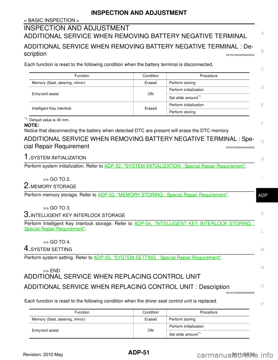
Each function is reset to the following condition when the battery terminal is disconnected.
*1: Default value is 40 mm.
NOTE:
Notice that disconnecting the battery when detect ed DTC are present will erase the DTC memory.
ADDITIONAL SERVICE WHEN REMOVING BATTERY NEGATIVE TERMINAL : Spe-
cial Repair Requirement
INFOID:0000000006248325
1.SYSTEM INITIALIZATION
Perform system initialization. Refer to ADP-52, "
SYSTEM INITIALIZATION : Special Repair Requirement".
>> GO TO 2.
2.MEMORY STORAGE
Perform memory storage. Refer to ADP-53, "
MEMORY STORING : Special Repair Requirement".
>> GO TO 3.
3.INTELLIGENT KEY INTERLOCK STORAGE
Perform Intelligent Key interlock storage. Refer to ADP-54, "
INTELLIGENT KEY INTERLOCK STORING :
Special Repair Requirement".
>> GO TO 4.
4.SYSTEM SETTING
Perform system setting. Refer to ADP-55, "
SYSTEM SETTING : Special Repair Requirement".
>> END
ADDITIONAL SERVICE WHEN REPLACING CONTROL UNIT
ADDITIONAL SERVICE WHEN REPL ACING CONTROL UNIT : Description
INFOID:0000000006248326
Each function is reset to the following condition when the driver seat control unit is replaced.
Function Condition Procedure
Memory (Seat, stee ring, mirror) Erased Perform storing
Entry/exit assist ON Perform initialization
Set slide amount
*1
Intelligent Key interlock Erased
Perform initialization
Perform storing
Function Condition Procedure
Memory (Seat, stee ring, mirror) Erased Perform storing
Entry/exit assist ON Perform initialization
Set slide amount
*1
Revision: 2010 May2011 QX56
Page 61 of 5598

ADP-52
< BASIC INSPECTION >
INSPECTION AND ADJUSTMENT
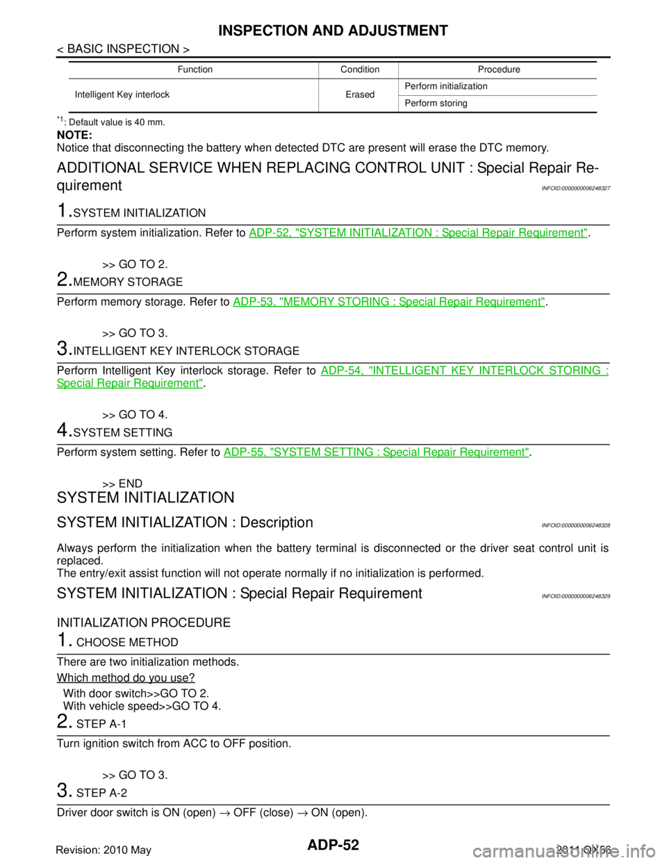
*1: Default value is 40 mm.
NOTE:
Notice that disconnecting the battery when detected DTC are present will erase the DTC memory.
ADDITIONAL SERVICE WHEN REPLACING CONTROL UNIT : Special Repair Re-
quirement
INFOID:0000000006248327
1.SYSTEM INITIALIZATION
Perform system initialization. Refer to ADP-52, "
SYSTEM INITIALIZATION : Special Repair Requirement".
>> GO TO 2.
2.MEMORY STORAGE
Perform memory storage. Refer to ADP-53, "
MEMORY STORING : Special Repair Requirement".
>> GO TO 3.
3.INTELLIGENT KEY INTERLOCK STORAGE
Perform Intelligent Key interlock storage. Refer to ADP-54, "
INTELLIGENT KEY INTERLOCK STORING :
Special Repair Requirement".
>> GO TO 4.
4.SYSTEM SETTING
Perform system setting. Refer to ADP-55, "
SYSTEM SETTING : Special Repair Requirement".
>> END
SYSTEM INITIALIZATION
SYSTEM INITIALIZATION : DescriptionINFOID:0000000006248328
Always perform the initialization when the battery termi nal is disconnected or the driver seat control unit is
replaced.
The entry/exit assist function will not operate normally if no initialization is performed.
SYSTEM INITIALIZATION : Special Repair RequirementINFOID:0000000006248329
INITIALIZATION PROCEDURE
1. CHOOSE METHOD
There are two initialization methods.
Which method do you use?
With door switch>>GO TO 2.
With vehicle speed>>GO TO 4.
2. STEP A-1
Turn ignition switch from ACC to OFF position.
>> GO TO 3.
3. STEP A-2
Driver door switch is ON (open) → OFF (close) → ON (open).
Intelligent Key interlock Erased Perform initialization
Perform storing
Function Condition Procedure
Revision: 2010 May2011 QX56
Page 62 of 5598

INSPECTION AND ADJUSTMENTADP-53
< BASIC INSPECTION >
C
DE
F
G H
I
K L
M A
B
ADP
N
O P
>> END
4. STEP B-1
Drive the vehicle at more than 25 km/h (16 MPH).
>> END
MEMORY STORING
MEMORY STORING : DescriptionINFOID:0000000006248330
Always perform the memory storage when the battery terminal is disconnected or the driver seat control unit is
replaced. The memory function will not operate normally if no memory storage is performed.
MEMORY STORING : Special Repair RequirementINFOID:0000000006248331
Memory Storage Procedure
Two positions for the driver seat, steering column and outside mirror can be stored for memory operation by
following procedure.
1.STEP 1
Check the following conditions.
Ignirion switch: ON
A/T shift selector: P position
>> GO TO 2.
2.STEP 2
Adjust driver seat, steering colu mn and outside mirror position manually.
>> GO TO 3.
3.STEP 3
1. Push set switch. NOTE:
Memory indicator for which driver seat position is already retained in memory is illuminated for 5 sec-
onds.
Memory indicator for which driver seat position is not retained in memory is illuminated for 0.5 second.
2. Push the memory switch (1 or 2) for at least 1 second within 5 seconds after pushing the set switch.
NOTE:
To enter driver seat positions into blank memo ry, memory indicator will be turned on for 5 seconds.
To modify driver seat positions, memory indicato r will be turned OFF for 0.5 second, then turned ON for
5 seconds.
NOTE:
If memory is stored in the same memory switch, the previous memory will be deleted.
>> GO TO 4.
4.STEP 4
Confirm the operation of each part with memory operation.
>> END
INTELLIGENT KEY IN TERLOCK STORING
Revision: 2010 May2011 QX56
Page 63 of 5598

ADP-54
< BASIC INSPECTION >
INSPECTION AND ADJUSTMENT
INTELLIGENT KEY INTERLOCK STORING : Description
INFOID:0000000006248332
Always perform the Intelligent Key interlock function st orage when the battery terminal is disconnected or the
driver seat control unit is replaced. The Intelligent Key interlock function will not operate normally if no memory
storage is performed.
INTELLIGENT KEY INTERLOCK STORIN G : Special Repair RequirementINFOID:0000000006248333
Intelligent Key Interlock Storage Procedure
Performing the following operation associates the regist ered driving position with Intelligent Key. When driver
door unlock operation is performed by Intelligent Key or driver door request switch, display of the registered
driving position and turnout operation can be performed.
1.STEP 1
Check the following conditions.
Ignition switch: OFF
Initialization: done
Driving position: registered
>> GO TO 2.
2.STEP 2
1. Push set switch. NOTE:
Memory indicator for which driver seat position is already retained in memory is illuminated for 5 seconds.
2. Push the Intelligent Key unlock button within 5 seconds after pushing memory switch (while the memory indicator is turned ON).
NOTE:
From the time registration is performed, the app licable memory indicator blinks for 5 seconds.
>> GO TO 3.
3.STEP 3
Confirm the operation of each part with memory operation and Intelligent Key interlock operation.
>> END
SYSTEM SETTING
SYSTEM SETTING : DescriptionINFOID:0000000006248334
The settings of the automatic driv ing positioner system can be changed, us ing CONSULT-III, the display unit
in the center of the instrument panel and the set s witch. Always check the settings before and after discon-
necting the battery terminal or replacing driver seat control unit.
Setting Change
× : Applicable
Item Content CON-
SULT
–III Display
Set
switch Factory
setting
Amount of seat sliding for
entry/exit assist The amount of seat sliding for entry/exit assist can
be selected from 3 items.
[40 mm/80 mm/150 mm]
x——40 mm
Entry/exit assist
(seat) Entry/exit assist (seat) can be selected:
ON (operated) – OFF (not operated)
xx
xON
Entry/exit assist
(steering column) Entry/exit assist (steering column) can be selected:
ON (operated) – OFF (not operated)
xx ON
Revision: 2010 May2011 QX56
Page 65 of 5598

ADP-56
< DTC/CIRCUIT DIAGNOSIS >
U1000 CAN COMM CIRCUIT
DTC/CIRCUIT DIAGNOSIS
U1000 CAN COMM CIRCUIT
DescriptionINFOID:0000000006248336
CAN (Controller Area Network) is a serial communication line for real time applications. It is an on-vehicle mul-
tiplex communication line with high data communication speed and excellent error detection ability. Modern
vehicle is equipped with many electronic control unit, and each control unit shares information and links with
other control units during operation (not independent). In CAN communication, control units are connected
with 2 communication lines (CAN H-line, CAN L-line) al lowing a high rate of information transmission with less
wiring. Each control unit transmits/receives data but selectively reads required data only.
DTC LogicINFOID:0000000006248337
DTC DETECTION LOGIC
DTC CONFIRMATION PROCEDURE
1.STEP 1
Turn ignition switch ON and wait at least 3 seconds.
>> GO TO 2.
2.STEP 2
Check “Self diagnostic result” with CONSULT-III.
Is the DTC detected?
YES >> Perform diagnosis procedure. Refer to ADP-56, "DiagnosisProcedure".
NO >> INSPECTION END
Diagnosis ProcedureINFOID:0000000006248338
Refer to LAN-18, "Trouble Diagnosis Flow Chart".
Special Repair RequirementINFOID:0000000006248339
Refer to ADP-52, "SYSTEM INITIALIZATION : Description".
DTC No. CONSULT-III display
description DTC detecting condition Possible cause
U1000 CAN COMM CIR-
CUIT Driver seat control unit cannot communicate to other
control units.
When driver seat control unit cannot communicate CAN communication signal continuously for 2 seconds or
more. CAN communication system
Revision: 2010 May2011 QX56
Page 67 of 5598

ADP-58
< DTC/CIRCUIT DIAGNOSIS >
B2112 SLIDING MOTOR
B2112 SLIDING MOTOR
DTC LogicINFOID:0000000006248342
DTC DETECTION LOGIC
DTC CONFIRMATION PROCEDURE
1.STEP 1
Turn ignition switch ON.
>> GO TO 2.
2.STEP 2
Check “Self diagnostic result” with CONSULT-III.
Is the DTC detected?
YES >> Perform diagnosis procedure. Refer to ADP-58, "DiagnosisProcedure".
NO >> INSPECTION END
Diagnosis ProcedureINFOID:0000000006248343
1.PERFORM DTC CONFIRMATION PROCEDURE
1. Turn ignition switch ON.
2. Check “Self diagnostic result” with CONSULT-III.
3. Erase the DTC.
4. Perform DTC confirmation procedure. Refer to ADP-58, "
DTC Logic".
Is the DTC displayed again?
YES >> GO TO 2.
NO >> Check intermittent incident. Refer to GI-40, "
Intermittent Incident".
2.CHECK SLIDING MOTOR CIRCUIT (POWER SHORT)
1. Turn ignition switch OFF.
2. Disconnect sliding motor and driver seat control unit connector.
3. Check voltage between sliding motor harness connector and ground.
Is the inspection result normal?
YES >> GO TO 3.
NO >> Repair or replace harness or connector.
3.CHECK DRIVER SEAT CONTROL UNIT OUTPUT SIGNAL
1. Connect driver seat control unit connector.
2. Check voltage between driver seat control unit harness connector and ground.
DTC No. Trouble diagnosis
name DTC detecting condition Possible cause
B2112 SEAT SLIDE The driver seat control unit detects the output of slid-
ing motor output terminal for 0.1 second or more
even if the sliding switch is not input. Driver seat control unit
Slide motor harness is shorted
(+)
(-)Voltage (V)
(Approx.)
Sliding motor
Connector Terminals
B461 34
Ground 0
38
Revision: 2010 May2011 QX56
Page 69 of 5598

ADP-60
< DTC/CIRCUIT DIAGNOSIS >
B2113 RECLINING MOTOR
B2113 RECLINING MOTOR
DTC LogicINFOID:0000000006248344
DTC DETECTION LOGIC
DTC CONFIRMATION PROCEDURE
1.STEP 1
Turn ignition switch ON.
>> GO TO 2.
2.STEP 2
Check “Self diagnostic result” with CONSULT-III.
Is the DTC detected?
YES >> Perform diagnosis procedure. Refer to ADP-60, "DiagnosisProcedure".
NO >> INSPECTION END
Diagnosis ProcedureINFOID:0000000006248345
1.PERFORM DTC CONFIRMATION PROCEDURE
1. Turn ignition switch ON.
2. Check “Self diagnostic result” with CONSULT-III.
3. Erase the DTC.
4. Perform DTC confirmation procedure. Refer to ADP-60, "
DTC Logic".
Is the DTC displayed again?
YES >> GO TO 2.
NO >> Check intermittent incident. Refer to GI-40, "
Intermittent Incident".
2.CHECK RECLINING MOTOR CIRCUIT (POWER SHORT)
1. Turn ignition switch OFF.
2. Disconnect reclining motor and driver seat control unit connector.
3. Check voltage between reclining motor harness connector and ground.
Is the inspection result normal?
YES >> GO TO 3.
NO >> Repair or replace harness or connector.
3.CHECK DRIVER SEAT CONTROL UNIT OUTPUT SIGNAL
1. Connect driver seat control unit connector.
2. Check voltage between driver seat control unit harness connector and ground.
DTC No. Trouble diagnosis
name DTC detecting condition Possible cause
B2113 SEAT RECLINING The driver seat control unit detects the output of re-
clining motor output terminal for 0.1 second or more
even if the reclining switch is not input. Driver seat control unit
Reclining motor harness is short-
ed
(+)
(-)Voltage (V)
(Approx.)
Reclining motor
Connector Terminals
B454 35
Ground 0
39
Revision: 2010 May2011 QX56