Fuel INFINITI QX56 2011 Factory User Guide
[x] Cancel search | Manufacturer: INFINITI, Model Year: 2011, Model line: QX56, Model: INFINITI QX56 2011Pages: 5598, PDF Size: 94.53 MB
Page 689 of 5598

BRM-14
< PREPARATION >
BODY COMPONENT PARTS
NOTE:
For the parts without a number described in the figure, it is supplied only with the assembly part that the part is included with.
Tensile strength column shows the largest strength value of a part in the component part.
CAUTION:
If the high strength steel (ultra high strength steel) of this is broken, replace by assembly for the supply part. No. Parts name
Tensile strength
(MPa) Both sided anti-corrosive
precoated steel sections
1. Frame assembly Refer to No.2−36
2. Front bumper crossmember assembly T=1.8 mm
(0.071 in)
980
caution—
3. 2nd crossmember assembly 440 —
4. 2nd crossmember reinforcement (RH & LH) 440 —
5. 1st cab mounting bracket (RH & LH) Under 440 —
6. Front side member assembly (RH & LH) 540 —
7. Front suspension bracket assembly (RH & LH) Under 440 —
8. Engine mounting bracket assembly (RH & LH) Under 440 —
9. 2nd cab mounting bracket assembly (RH & LH) Under 440 —
10. 3way connector bracket assembly (RH & LH) Under 440 —
11. Piping bracket assembly (RH & LH) Under 440 —
12. Front bound bumper bracket assembly (RH & LH) 540 —
13. Lower front link mounting bracket assembly (RH & LH) 440 —
14. Diagonal member complete (RH & LH) 540 —
15. Rear engine mounting gusset assembly Under 440 —
16. Rear engine mounting member complete Under 440 —
17. Front fuel tank protector (RH & LH) Under 440 —
18. 3rd cab mounting bracket assembly (RH & LH) Under 440 —
19. Center side member assembly (RH & LH) 540 —
20. 6th crossmember assembly Under 440 —
21. Exhaust bracket (Front) Under 440 —
22. Fuel tank protector (RH & LH Rear) Under 440 —
23. Heat insulator bracket Under 440 —
24. Fuel tank protector assembly (RH & LH) 540 —
25. Rear suspension mounting bracket assembly (RH & LH) 540 —
26. 4th cab body mounting bracket assembly (RH & LH) Under 440 —
27. Rear brake hose bracket (RH & LH) Under 440 —
28. Rear shock absorber bracket assembly (RH & LH) 540 —
29. Rear side member assembly (RH & LH) 540 —
30. 5th cab body bracket (RH & LH) Under 440 —
31. 7th crossmember assembly Under 440 —
32. Exhaust bracket (Rear) Under 440 —
33. Spare wheel crossmember assembly Under 440 —
34. Front under cover bracket assembly Under 440 —
35. Rear end gusset (RH & LH) 440 —
36. Rear end crossmember assembly 540 —
Revision: 2010 May2011 QX56
Page 807 of 5598
![INFINITI QX56 2011 Factory User Guide
CCS-72
< BASIC INSPECTION >[ICC]
LASER BEAM AIMING ADJUSTMENT
LASER BEAM AIMING ADJUSTMENT
DescriptionINFOID:0000000006224293
OUTLINE OF LASER BEAM AIMING ADJUSTMENT
Always adjust the laser beam aimi INFINITI QX56 2011 Factory User Guide
CCS-72
< BASIC INSPECTION >[ICC]
LASER BEAM AIMING ADJUSTMENT
LASER BEAM AIMING ADJUSTMENT
DescriptionINFOID:0000000006224293
OUTLINE OF LASER BEAM AIMING ADJUSTMENT
Always adjust the laser beam aimi](/img/42/57033/w960_57033-806.png)
CCS-72
< BASIC INSPECTION >[ICC]
LASER BEAM AIMING ADJUSTMENT
LASER BEAM AIMING ADJUSTMENT
DescriptionINFOID:0000000006224293
OUTLINE OF LASER BEAM AIMING ADJUSTMENT
Always adjust the laser beam aiming after removing and installing or replacing the ICC sensor.
CAUTION:
The system does not operate normally
unless the laser beam aiming adjustment is performed. Always
perform it.
1. Set the ICC target board [SST: KV99110100 (J-45718)] to the correct position in front of the vehicle.
2. Set the laser beam aiming mode (“LASER BEAM AD JUST” on “Work support”) with CONSULT-III, and
then perform the adjustment according to the displa y. (Manually turn the up-down direction adjusting
screw for vertical adjustment. ICC sensor adjusts the automatic aiming for the horizontal direction.)
CAUTIONARY POINT FOR LASER BEAM AIMING ADJUSTMENT
CAUTION:
For laser beam aiming adjustment, choose a level location where a view can be obtained without any
obstruction as far as 12 m (39 ft) or more in the forward direction.
Adjust laser beam aiming for 5 second s or more after starting engine.
Adjust the laser beam aiming with CONSULT-III. (The laser beam aiming cannot be adjusted without
CONSULT-III.)
Never enter the vehicle during laser beam aiming adjustment.
Never look directly into the laser beam sour ce (ICC sensor body window) during laser beam aiming
adjustment.
Laser beam aiming adjustment is performed at idle. At this time, turn the headlamps OFF.
Work Procedure (Preparation)INFOID:0000000006224294
1.ADVANCE PREPARATION FOR LASER BEAM AIMING ADJUSTMENT
1. Adjust all tire pressure to the specified value.
2. Empty the vehicle. (Remove any luggage from the passenger compartment, luggage room, etc.)
3. Shift the selector lever to “P” pos ition, and release the parking brake.
4. Fully fill the fuel tank, and then check that t he coolant and oils are filled up to correct level.
5. Clean off the ICC sensor body window with a soft cloth.
>> Go to CCS-72, "
Work Procedure (Setting The ICC Tar-
get Board)".
Work Procedure (Setting The ICC Target Board)INFOID:0000000006224295
DESCRIPTION
Accurate adjustment of the laser beam requires t hat the ICC target board be accurately positioned.
CAUTION:
If the laser beam is adjusted with the ICC target board in the incorrect position, the ICC system does
not function normally.
1.ICC TARGET BOARD HEIGHT ADJUSTMENT
1 : ICC sensor
JSOIA0372ZZ
Revision: 2010 May2011 QX56
Page 921 of 5598

CHG-8
< SYSTEM DESCRIPTION >
SYSTEM
scription
INFOID:0000000006274863
By performing the power generation voltage variable c ontrol, the engine load due to the power generation of
the alternator is reduced and fuel consumption is decreased.
NOTE:
When any malfunction is detected in the power generat ion voltage variable control system, the power genera-
tion is performed according to the characteristic of the IC voltage regulator of the alternator.
Revision: 2010 May2011 QX56
Page 963 of 5598
WATER INLET AND THERMOSTAT ASSEMBLYCO-21
< REMOVAL AND INSTALLATION >
C
DE
F
G H
I
J
K L
M A
CO
NP
O
2. Remove front under cover with power tool. Refer to
EXT-25, "Exploded View".
3. Drain engine coolant from drain plugs on radiator and cylinder block. Refer to CO-8, "
Draining" and EM-
103, "Setting".
CAUTION:
Perform this step when engine is cold.
Never spill engine coolant on drive belts.
4. Disconnect radiator hose (upper and lower). Refer to CO-13, "
Exploded View".
5. Remove intake manifold. Refer to EM-30, "
Exploded View".
6. Remove fuel feed tube. Refer to EM-43, "
Exploded View".
7. Remove water hose, water connector, heater pipes and heater hoses.
8. Remove thermostat housing.
9. Remove water inlet and thermostat.
INSTALLATION
Note the following, and install in the reverse order of removal.
CAUTION:
Be careful not to spill engine coolant over en gine room. Use rag to absorb engine coolant.
Thermostat
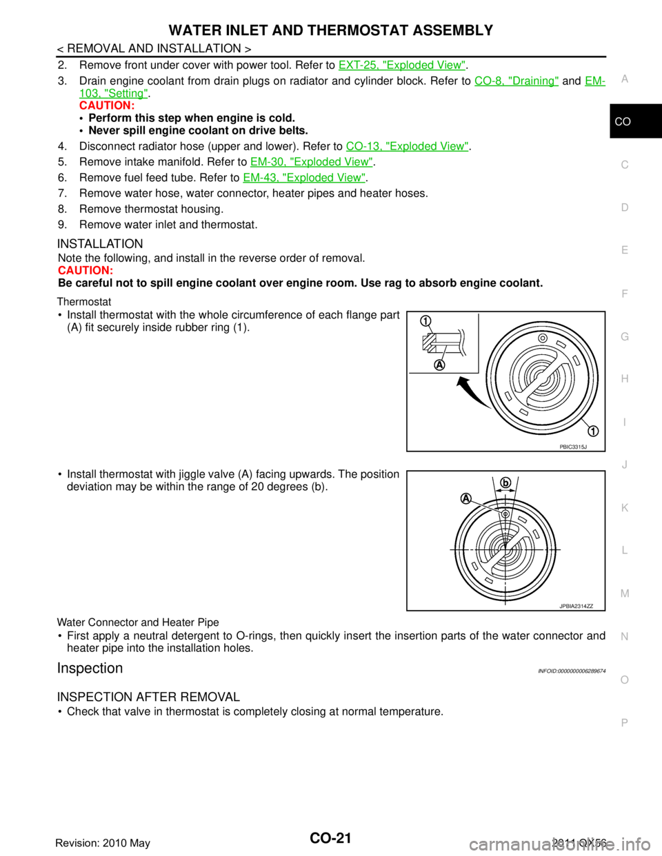
Install thermostat with the whole circumference of each flange part
(A) fit securely inside rubber ring (1).
Install thermostat with jiggle valve (A) facing upwards. The position deviation may be within the range of 20 degrees (b).
Water Connector and Heater Pipe
First apply a neutral detergent to O-rings, then quickly in sert the insertion parts of the water connector and
heater pipe into the installation holes.
InspectionINFOID:0000000006289674
INSPECTION AFTER REMOVAL
Check that valve in thermostat is co mpletely closing at normal temperature.
PBIC3315J
JPBIA2314ZZ
Revision: 2010 May2011 QX56
Page 1305 of 5598
![INFINITI QX56 2011 Factory User Guide
DAS-340
< BASIC INSPECTION >[LDW & LDP]
CAMERA AIMING ADJUSTMENT
CAMERA AIMING ADJUSTMENT
DescriptionINFOID:0000000006223734
Always adjust the camera aiming after removing
and installing or replacin INFINITI QX56 2011 Factory User Guide
DAS-340
< BASIC INSPECTION >[LDW & LDP]
CAMERA AIMING ADJUSTMENT
CAMERA AIMING ADJUSTMENT
DescriptionINFOID:0000000006223734
Always adjust the camera aiming after removing
and installing or replacin](/img/42/57033/w960_57033-1304.png)
DAS-340
< BASIC INSPECTION >[LDW & LDP]
CAMERA AIMING ADJUSTMENT
CAMERA AIMING ADJUSTMENT
DescriptionINFOID:0000000006223734
Always adjust the camera aiming after removing
and installing or replacing the lane camera unit.
CAUTION:
Place the vehicle on level ground when th e camera aiming adjustment is operated.
Follow the CONSULT-III when performing the came ra aiming. (Camera aiming adjustment cannot be
operated without CONSULT-III.)
Work Procedure (Preparation)INFOID:0000000006223735
1.PERFORM SELF-DIAGNOSIS
Perform self-diagnosis of ADAS control unit and lane camera unit.
Is any DTC detected?
Except “C1B01”>>Perform diagnosis on the detected DTC and repair or replace the applicable item. Refer to
DAS-310, "
DTC Index" (ICC/ADAS) or DAS-316, "DTC Index" (LANE CAMERA).
“C1B01” or no DTC>>GO TO 2.
2.PREPARATION BEFORE CAMERA AIMING ADJUSTMENT
1. Perform pre-inspection for diagnosis. Refer to DAS-335, "
Inspection Procedure".
2. Adjust the tire pressure to the specified pressure value.
3. Maintain no-load in vehicle.
4. Check if coolant and engine oil are filled up to correct level and fuel tank is full.
5. Shift the selector lever to “P” position and release the parking brake.
6. Clean the windshield.
7. Completely clear off the instrument panel.
>> GO TO 3.
3. PREPARATION OF AIMING ADJUSTMENT JIG
Prepare the aiming adjustment jig according to the following procedure and the figure.
1. Print out the target mark attached in this service manual. Refer to DAS-343, "
Work Procedure (Target
Mark Sample)".
2. Stick a printed target mark on the board with a scotch tape or a piece of double-sided tape.
NOTE:
Use the board that peripheral area of the ta rget is monochrome such as a white-board.
Notice that the cross of the target is horizontal and vertical.
JPOIA0011ZZ
Revision: 2010 May2011 QX56
Page 1539 of 5598
DLK-3
C
DE
F
G H
I
J
L
M A
B
DLK
N
O P
Diagnosis Procedure ...........................................
....
98
B2423 AUTOMATIC BACK DOOR MOTOR
OPERATION TIME .............................................
99
DTC Logic ........................................................... ....99
Diagnosis Procedure ...............................................99
B2424 CLOSURE CONDITION ........................100
DTC Logic ........................................................... ..100
Diagnosis Procedure .............................................100
Component Inspection ..........................................101
B2425 AUTOMATIC BACK DOOR CONTROL
UNIT ..................................................................
103
DTC Logic ........................................................... ..103
Diagnosis Procedure .............................................103
B2621 INSIDE ANTENNA ................................104
DTC Logic ........................................................... ..104
Diagnosis Procedure .............................................104
B2622 INSIDE ANTENNA ................................106
DTC Logic ........................................................... ..106
Diagnosis Procedure .............................................106
B2623 INSIDE ANTENNA ................................108
DTC Logic ........................................................... ..108
Diagnosis Procedure .............................................108
B2626 OUTSIDE ANTENNA ............................110
DTC Logic ........................................................... ..110
Diagnosis Procedure .............................................110
B2627 OUTSIDE ANTENNA ............................112
DTC Logic ........................................................... ..112
Diagnosis Procedure .............................................112
B2628 OUTSIDE ANTENNA ............................114
DTC Logic ........................................................... ..114
Diagnosis Procedure .............................................114
POWER SUPPLY AND GROUND CIRCUIT ....116
AUTOMATIC BACK DOOR CONTROL UNIT ...... ..116
AUTOMATIC BACK DOOR CONTROL UNIT : Di-
agnosis Procedure ................................................
116
DOOR SWITCH ................................................117
Component Function Check .............................. ..117
Diagnosis Procedure .............................................117
Component Inspection ..........................................119
BACK DOOR SWITCH .....................................120
Component Function Check .............................. ..120
Diagnosis Procedure .............................................120
Component Inspection ..........................................121
DOOR LOCK AND UNLOCK SWITCH ............122
DRIVER SIDE ........................................................ ..122
DRIVER SIDE : Component Function Check ......122
DRIVER SIDE : Diagnosis Procedure ...................122
PASSENGER SIDE ..................................................122
PASSENGER SIDE :
Component Function Check .............................. ..
122
PASSENGER SIDE : Diagnosis Procedure ..........122
DOOR LOCK ACTUATOR ..............................123
DRIVER SIDE ......................................................... ..123
DRIVER SIDE : Component Function Check ......123
DRIVER SIDE : Diagnosis Procedure ...................123
PASSENGER SIDE ..................................................124
PASSENGER SIDE :
Component Function Check .............................. ..
124
PASSENGER SIDE : Diagnosis Procedure ..........124
REAR LH ................................................................ ..125
REAR LH : Component Function Check ..............125
REAR LH : Diagnosis Procedure ...........................125
REAR RH ............................................................... ..126
REAR RH : Component Function Check .............126
REAR RH : Diagnosis Procedure ..........................126
FUEL LID LOCK ACTUATOR ........................128
Component Function Check ................................128
Diagnosis Procedure .............................................128
UNLOCK SENSOR .........................................130
Component Function Check ................................130
Diagnosis Procedure .............................................130
Component Inspection ...........................................131
DOOR KEY CYLINDER SWITCH ...................132
Component Function Check ..................................132
Diagnosis Procedure .............................................132
Component Inspection ...........................................133
REMOTE KEYLESS ENTRY RECEIVER .......134
Component Function Check ................................134
Diagnosis Procedure .............................................134
DOOR REQUEST SWITCH ............................137
Component Function Check ................................137
Diagnosis Procedure .............................................137
Component Inspection ...........................................138
BACK DOOR REQUEST SWITCH .................139
Component Function Check ................................139
Diagnosis Procedure .............................................139
Component Inspection ...........................................140
BACK DOOR OPENER SWITCH ...................141
Component Function Check ................................141
Diagnosis Procedure .............................................141
Component Inspection ...........................................142
INTELLIGENT KEY WARNING BUZZER .......143
Component Function Check ................................143
Diagnosis Procedure .............................................143
Component Inspection ...........................................144
INTELLIGENT KEY .........................................145
Revision: 2010 May2011 QX56
Page 1541 of 5598

DLK-5
C
DE
F
G H
I
J
L
M A
B
DLK
N
O P
FUEL LID LOCK ACTUATOR DOES NOT OP-
ERATE ............................................................ ..
176
Diagnosis Procedure ........................................... ..176
IGNITION POSITION WARNING FUNCTION
DOES NOT OPERATE .....................................
177
Diagnosis Procedure ........................................... ..177
SELECTIVE UNLOCK FUNCTION DOES
NOT OPERATE ................................................
178
Diagnosis Procedure ........................................... ..178
AUTO DOOR LOCK OPERATION DOES NOT
OPERATE .........................................................
179
Diagnosis Procedure ........................................... ..179
VEHICLE SPEED SENSING AUTO LOCK
OPERATION DOES NOT OPERATE ..............
180
Diagnosis Procedure ........................................... ..180
IGN OFF INTERLOCK DOOR UNLOCK
FUNCTION DOES NOT OPERATE .................
181
Diagnosis Procedure ........................................... ..181
P RANGE INTERLOCK DOOR LOCK/UN-
LOCK FUNCTION DOES NOT OPERATE ......
182
Diagnosis Procedure ........................................... ..182
HAZARD AND HORN REMINDER DOES
NOT OPERATE ................................................
183
Diagnosis Procedure ........................................... ..183
HAZARD AND BUZZER REMINDER DOES
NOT OPERATE ................................................
184
Diagnosis Procedure ........................................... ..184
KEY REMINDER FUNCTION DOES NOT OP-
ERATE ..............................................................
185
Diagnosis Procedure ........................................... ..185
WELCOME LIGHT FUNCTION DOES NOT
OPERATE .........................................................
186
Diagnosis Procedure ........................................... ..186
OFF POSITION WARNING DOES NOT OP-
ERATE ..............................................................
188
Diagnosis Procedure ........................................... ..188
P POSITION WARNING DOES NOT OPER-
ATE ...................................................................
189
Description .......................................................... ..189
Diagnosis Procedure .............................................189
ACC WARNING DOES NOT OPERATE .........191
Description .......................................................... ..191
Diagnosis Procedure .............................................191
TAKE AWAY WARNING DOES NOT OPER-
ATE ...................................................................
192
Description .......................................................... ..192
Diagnosis Procedure .............................................192
KEY ID WARNING DOES NOT OPERATE ....194
Description ........................................................... ..194
Diagnosis Procedure .............................................194
INTELLIGENT KEY LOW BATTERY WARN-
ING DOES NOT OPERATE ............................
195
Description .............................................................195
Diagnosis Procedure .............................................195
DOOR LOCK OPERATION WARNING DOES
NOT OPERATE ...............................................
197
Diagnosis Procedure .............................................197
AUTOMATIC BACK DOOR OPERATION
DOES NOT OPERATE ....................................
198
ALL SWITCHES ..................................................... ..198
ALL SWITCHES : Description ...............................198
ALL SWITCHES : Diagnosis Procedure ................198
AUTOMATIC BACK DOOR SWITCH .................... ..199
AUTOMATIC BACK DOOR SWITCH : Descrip-
tion .........................................................................
199
AUTOMATIC BACK DOOR SWITCH : Diagnosis
Procedure ..............................................................
199
AUTOMATIC BACK DOOR CLOSE SWITCH ........199
AUTOMATIC BACK DOOR CLOSE SWITCH :
Description ........................................................... ..
199
AUTOMATIC BACK DOOR CLOSE SWITCH : Di-
agnosis Procedure .................................................
199
INTELLIGENT KEY ................................................ ..200
INTELLIGENT KEY : Description ..........................200
INTELLIGENT KEY : Diagnosis Procedure ......... ..200
BACK DOOR OPENER SWITCH .......................... ..200
BACK DOOR OPENER SWITCH : Description .....200
BACK DOOR OPENER SWITCH : Diagnosis Pro-
cedure ....................................................................
200
OPEN/CLOSURE FUNCTION ............................... ..201
OPEN/CLOSURE FUNCTION : Description .........201
OPEN/CLOSURE FUNCTION : Diagnosis Proce-
dure .......................................................................
201
OPEN FUNCTION .................................................. ..202
OPEN FUNCTION : Description ............................202
OPEN FUNCTION : Diagnosis Procedure ............202
CLOSURE FUNCTION .......................................... ..202
CLOSURE FUNCTION : Description .....................202
CLOSURE FUNCTION : Diagnosis Procedure .....203
AUTOMATIC BACK DOOR WARNING DOES
NOT OPERATE ...............................................
204
BUZZER ................................................................. ..204
BUZZER : Description ...........................................204
BUZZER : Diagnosis Procedure ............................204
HAZARD WARNING LAMP ................................... ..204
HAZARD WARNING LAMP : Description ..............204
Revision: 2010 May2011 QX56
Page 1543 of 5598
DLK-7
C
DE
F
G H
I
J
L
M A
B
DLK
N
O P
Exploded View ....................................................
..
243
DOOR LOCK ......................................................... ..243
DOOR LOCK : Removal and Installation ..............243
INSIDE HANDLE ................................................... ..243
INSIDE HANDLE : Removal and Installation ........244
OUTSIDE HANDLE ............................................... ..244
OUTSIDE HANDLE : Removal and Installation ....244
BACK DOOR LOCK .........................................246
Exploded View .................................................... ..246
DOOR LOCK ......................................................... ..246
DOOR LOCK : Removal and Installation ..............246
TOUCH SENSOR .................................................. ..246
TOUCH SENSOR : Removal and Installation .......246
BACK DOOR SUPPORT ROD .............................. ..247
BACK DOOR SUPPORT ROD : Removal and In-
stallation ................................................................
247
EMERGENCY LEVER ........................................... ..247
EMERGENCY LEVER : Unlock procedures .........247
FUEL FILLER LID OPENER ............................248
Exploded View .................................................... ..248
Removal and Installation .......................................248
KEY CYLINDER ...............................................250
GLOVE BOX LID KEY CYLINDER ....................... ..250
GLOVE BOX LID KEY CYLINDER : Removal and
Installation .............................................................
250
CAB MOUNTING INSULATOR ........................251
Exploded View .................................................... ..251
Removal and Installation .......................................251
DOOR SWITCH ................................................254
Removal and Installation ..................................... ..254
DOOR REQUEST SWITCH ..............................255
DRIVER SIDE ........................................................ ..255
DRIVER SIDE : Removal and Installation .............255
PASSENGER SIDE .................................................255
PASSENGER SIDE : Removal and Installation .. ..255
BACK DOOR ......................................................... ..255
BACK DOOR : Removal and Installation ..............255
INSIDE KEY ANTENNA ..................................256
INSTRUMENT CENTER ........................................ ..256
INSTRUMENT CENTER : Removal and Installa-
tion .........................................................................
256
CONSOLE .............................................................. ..256
CONSOLE : Removal and Installation ...................256
LUGGAGE ROOM ................................................. ..256
LUGGAGE ROOM : Removal and Installation ......256
OUTSIDE KEY ANTENNA ..............................257
DRIVER SIDE ......................................................... ..257
DRIVER SIDE : Removal and Installation .............257
PASSENGER SIDE ..................................................257
PASSENGER SIDE : Removal and Installation .. ..257
BACK DOOR ......................................................... ..257
BACK DOOR : Removal and Installation ...............257
INTELLIGENT KEY WARNING BUZZER .......258
Removal and Installation .......................................258
REMOTE KEYLESS ENTRY RECEIVER .......259
Removal and Installation .......................................259
INTELLIGENT KEY BATTERY .......................260
Removal and Installation .......................................260
BACK DOOR CONTROL UNIT ......................261
Removal and Installation ..................................... ..261
AUTOMATIC BACK DOOR CONTROL MOD-
ULE ..................................................................
262
Removal and Installation .......................................262
AUTOMATIC BACK DOOR WARNING BUZZ-
ER ....................................................................
263
Removal and Installation .......................................263
AUTOMATIC BACK DOOR MAIN SWITCH ...264
Removal and Installation .......................................264
AUTOMATIC BACK DOOR CLOSE SWITCH .265
Removal and Installation ..................................... ..265
AUTOMATIC BACK DOOR SWITCH .............266
Removal and Installation .......................................266
Revision: 2010 May2011 QX56
Page 1548 of 5598
DLK-12
< SYSTEM DESCRIPTION >
COMPONENT PARTS
DOOR LOCK SYSTEM : Component Description
INFOID:0000000006225834
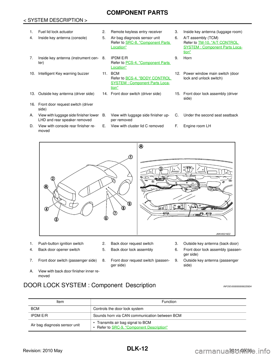
1. Fuel lid lock actuator 2. Remote keyless entry receiver 3. Inside key antenna (luggage room)
4. Inside key antenna (console) 5. Air bag diagnosis sensor unit Refer to SRC-8, "
Component Parts
Location"
6. A/T assembly (TCM)
Refer to TM-10, "
A/T CONTROL
SYSTEM : Component Parts Loca-
tion"
7. Inside key antenna (instrument cen-
ter) 8. IPDM E/R
Refer to PCS-4, "
Component Parts
Location"
9. Horn
10. Intelligent Key warning buzzer 11. BCM Refer to BCS-4, "
BODY CONTROL
SYSTEM : Component Parts Loca-
tion"
12. Power window main switch (door
lock and unlock switch)
13. Outside key antenna (driver side) 14. Front door switch (driver side) 15. Front door lock assembly (driver side)
16. Front door request switch (driver side)
A. View with luggage side finisher lower LHD and rear speaker removed B. View with luggage side finisher up-
per removed C. Under the second seat seatback
D. View with console rear finisher re- moved E. View with cluster lid C removed F. Engine room LH
1. Push-button ignition switch 2. Back door request switch 3. Outside key antenna (back door)
4. Back door opener switch 5. Back door lock assembly 6. Front door lock assembly (passen- ger side)
7. Front door switch (passenger side) 8. Front door request switch (passen- ger side)9. Outside key antenna (passenger
side)
A. View with back door finisher inner re- moved
JMKIA5218ZZ
Item Function
BCM Controls the door lock system
IPDM E/R Sounds horn via CAN communication between BCM
Air bag diagnosis sensor unit Transmits air bag signal to BCM
Refer to
SRC-9, "
Component Description"
Revision: 2010 May2011 QX56
Page 1549 of 5598
COMPONENT PARTSDLK-13
< SYSTEM DESCRIPTION >
C
DE
F
G H
I
J
L
M A
B
DLK
N
O P
AUTOMATIC BACK DOOR SYSTEM
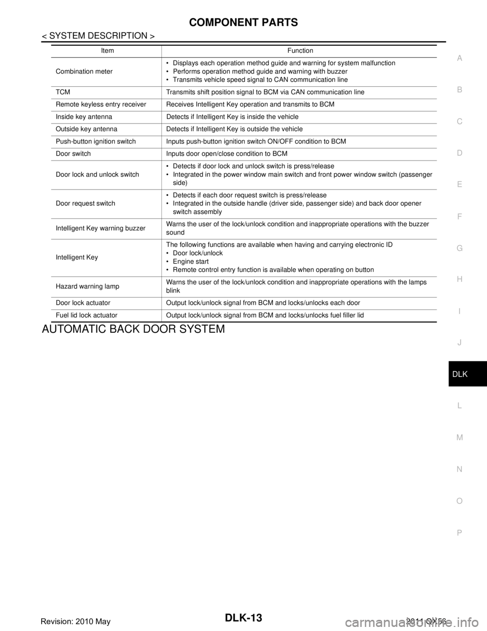
Combination meter Displays each operation method guide and warning for system malfunction
Performs operation method guide and warning with buzzer
Transmits vehicle speed signal to CAN communication line
TCM Transmits shift position signal to BCM via CAN communication line
Remote keyless entry receiver Receives Intelligent Key operation and transmits to BCM
Inside key antenna Detects if Intelligent Key is inside the vehicle
Outside key antenna Detects if Intelligent Key is outside the vehicle
Push-button ignition switch Inputs push-button ignition switch ON/OFF condition to BCM
Door switch Inputs door open/close condition to BCM
Door lock and unlock switch Detects if door lock and unlock switch is press/release
Integrated in the power window main switch and front power window switch (passenger
side)
Door request switch Detects if each door request switch is press/release
Integrated in the outside handle (driver side, passenger side) and back door opener
switch assembly
Intelligent Key warning buzzer Warns the user of the lock/unlock condition and inappropriate operations with the buzzer
sound
Intelligent Key The following functions are available when having and carrying electronic ID
Door lock/unlock
Engine start
Remote control entry function is available when operating on button
Hazard warning lamp Warns the user of the lock/unlock condition and inappropriate operations with the lamps
blink
Door lock actuator Output lock/unlock signal from BCM and locks/unlocks each door
Fuel lid lock actuator Output lock/unlock signal from BCM and locks/unlocks fuel filler lid Item Function
Revision: 2010 May2011 QX56