Fuel INFINITI QX56 2011 Factory Owner's Guide
[x] Cancel search | Manufacturer: INFINITI, Model Year: 2011, Model line: QX56, Model: INFINITI QX56 2011Pages: 5598, PDF Size: 94.53 MB
Page 1662 of 5598
DLK-126
< DTC/CIRCUIT DIAGNOSIS >
DOOR LOCK ACTUATOR
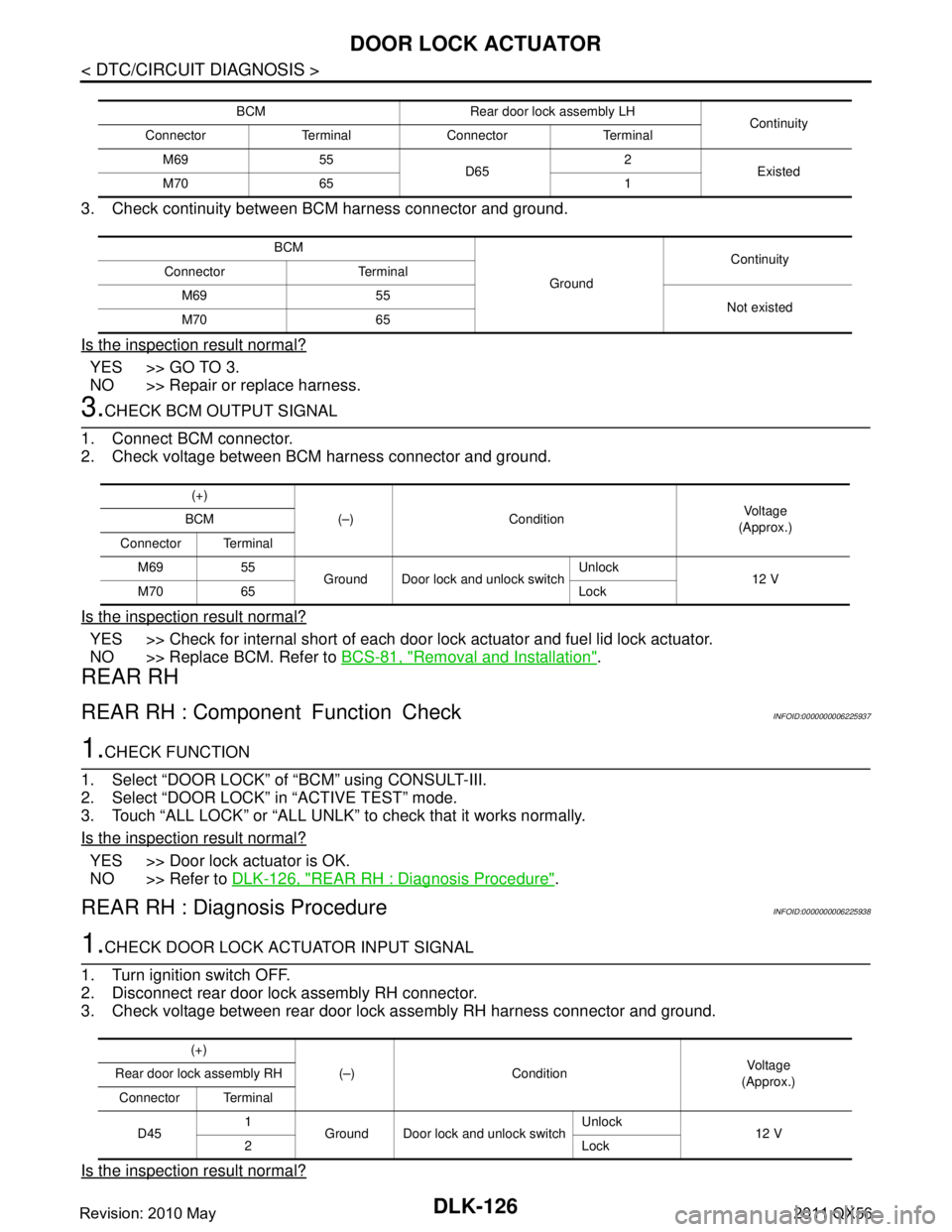
3. Check continuity between BCM harness connector and ground.
Is the inspection result normal?
YES >> GO TO 3.
NO >> Repair or replace harness.
3.CHECK BCM OUTPUT SIGNAL
1. Connect BCM connector.
2. Check voltage between BCM harness connector and ground.
Is the inspection result normal?
YES >> Check for internal short of each door lock actuator and fuel lid lock actuator.
NO >> Replace BCM. Refer to BCS-81, "
Removal and Installation".
REAR RH
REAR RH : Component Function CheckINFOID:0000000006225937
1.CHECK FUNCTION
1. Select “DOOR LOCK” of “BCM” using CONSULT-III.
2. Select “DOOR LOCK” in “ACTIVE TEST” mode.
3. Touch “ALL LOCK” or “ALL UNLK” to check that it works normally.
Is the inspection result normal?
YES >> Door lock actuator is OK.
NO >> Refer to DLK-126, "
REAR RH : Diagnosis Procedure".
REAR RH : Diagnosis ProcedureINFOID:0000000006225938
1.CHECK DOOR LOCK ACTUATOR INPUT SIGNAL
1. Turn ignition switch OFF.
2. Disconnect rear door lock assembly RH connector.
3. Check voltage between rear door lock assembly RH harness connector and ground.
Is the inspection result normal?
BCM Rear door lock assembly LH Continuity
Connector Terminal Connector Terminal
M69 55 D652
Existed
M70 65 1
BCM GroundContinuity
Connector Terminal
M69 55 Not existed
M70 65
(+)
(–) Condition Vo l ta g e
(Approx.)
BCM
Connector Terminal M69 55 Ground Door lock and unlock switch Unlock
12 V
M70 65 Lock
(+)
(–) Condition Vol tag e
(Approx.)
Rear door lock assembly RH
Connector Terminal
D45 1
Ground Door lock and unlock switch Unlock
12 V
2Lock
Revision: 2010 May2011 QX56
Page 1663 of 5598
DOOR LOCK ACTUATORDLK-127
< DTC/CIRCUIT DIAGNOSIS >
C
DE
F
G H
I
J
L
M A
B
DLK
N
O P
YES >> Replace rear door lock assembly RH.
NO >> GO TO 2.
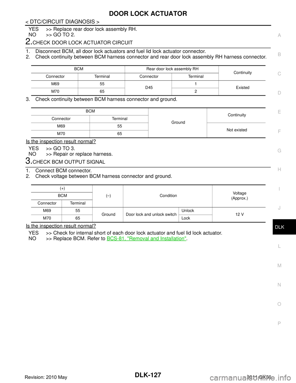
2.CHECK DOOR LOCK ACTUATOR CIRCUIT
1. Disconnect BCM, all door lock actuator s and fuel lid lock actuator connector.
2. Check continuity between BCM harness connector and rear door lock assembly RH harness connector.
3. Check continuity between BCM harness connector and ground.
Is the inspection result normal?
YES >> GO TO 3.
NO >> Repair or replace harness.
3.CHECK BCM OUTPUT SIGNAL
1. Connect BCM connector.
2. Check voltage between BCM harness connector and ground.
Is the inspection result normal?
YES >> Check for internal short of each door lo ck actuator and fuel lid lock actuator.
NO >> Replace BCM. Refer to BCS-81, "
Removal and Installation".
BCM Rear door lock assembly RH
Continuity
Connector Terminal Connector Terminal
M69 55 D451
Existed
M70 65 2
BCM GroundContinuity
Connector Terminal
M69 55 Not existed
M70 65
(+)
(–) Condition Vo l ta g e
(Approx.)
BCM
Connector Terminal M69 55 Ground Door lock and unlock switch Unlock
12 V
M70 65 Lock
Revision: 2010 May2011 QX56
Page 1664 of 5598
DLK-128
< DTC/CIRCUIT DIAGNOSIS >
FUEL LID LOCK ACTUATOR
FUEL LID LOCK ACTUATOR
Component Function CheckINFOID:0000000006225939
1.CHECK FUNCTION
1. Select “DOOR LOCK” of “BCM” using CONSULT-III.
2. Select “DOOR LOCK” in “ACTIVE TEST” mode.
3. Touch “ALL LOCK” or “ALL UNLK” to check that it works normally.
Is the inspection result normal?
YES >> Fuel lid lock actuator is OK.
NO >> Refer to DLK-128, "
Diagnosis Procedure".
Diagnosis ProcedureINFOID:0000000006225940
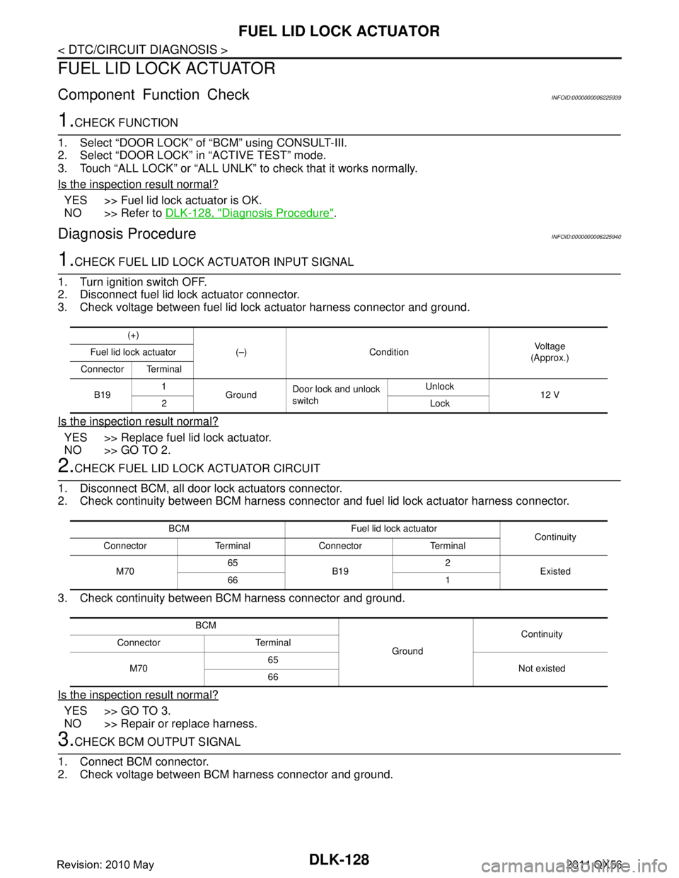
1.CHECK FUEL LID LOCK ACTUATOR INPUT SIGNAL
1. Turn ignition switch OFF.
2. Disconnect fuel lid lock actuator connector.
3. Check voltage between fuel lid lock actuator harness connector and ground.
Is the inspection result normal?
YES >> Replace fuel lid lock actuator.
NO >> GO TO 2.
2.CHECK FUEL LID LOCK ACTUATOR CIRCUIT
1. Disconnect BCM, all door lock actuators connector.
2. Check continuity between BCM harness connector and fuel lid lock actuator harness connector.
3. Check continuity between BCM harness connector and ground.
Is the inspection result normal?
YES >> GO TO 3.
NO >> Repair or replace harness.
3.CHECK BCM OUTPUT SIGNAL
1. Connect BCM connector.
2. Check voltage between BCM harness connector and ground.
(+)
(–) Condition Voltag e
(Approx.)
Fuel lid lock actuator
Connector Terminal
B19 1
Ground Door lock and unlock
switch Unlock
12 V
2Lock
BCM Fuel lid lock actuator Continuity
Connector Terminal Connector Terminal
M70 65
B19 2
Existed
66 1
BCM GroundContinuity
Connector Terminal
M70 65
Not existed
66
Revision: 2010 May2011 QX56
Page 1665 of 5598
FUEL LID LOCK ACTUATORDLK-129
< DTC/CIRCUIT DIAGNOSIS >
C
DE
F
G H
I
J
L
M A
B
DLK
N
O P
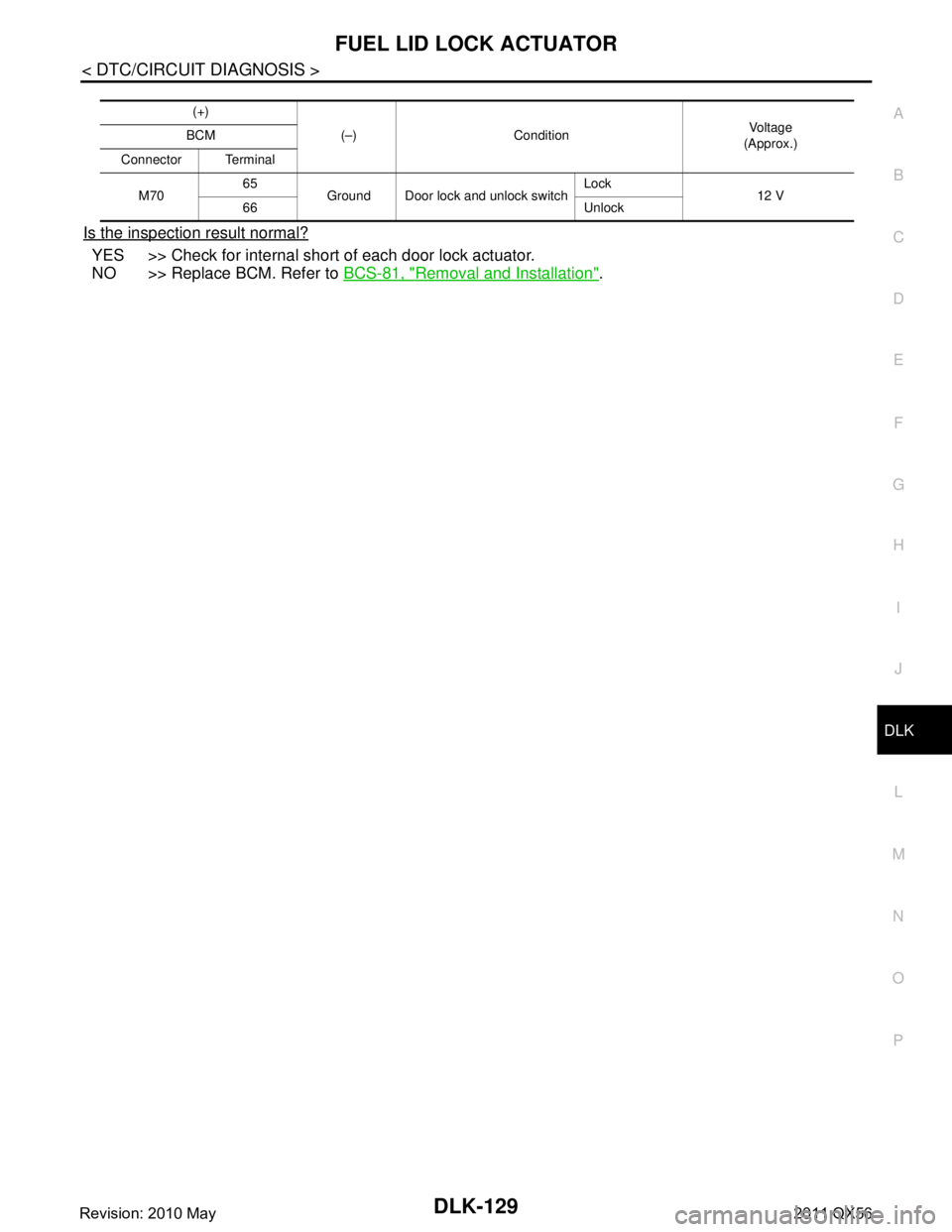
Is the inspection result normal?
YES >> Check for internal short of each door lock actuator.
NO >> Replace BCM. Refer to BCS-81, "
Removal and Installation".
(+)
(–) Condition Vo l ta g e
(Approx.)
BCM
Connector Terminal
M70 65
Ground Door lock and unlock switch Lock
12 V
66 Unlock
Revision: 2010 May2011 QX56
Page 1712 of 5598
DLK-176
< SYMPTOM DIAGNOSIS >
FUEL LID LOCK ACTUATOR DOES NOT OPERATE
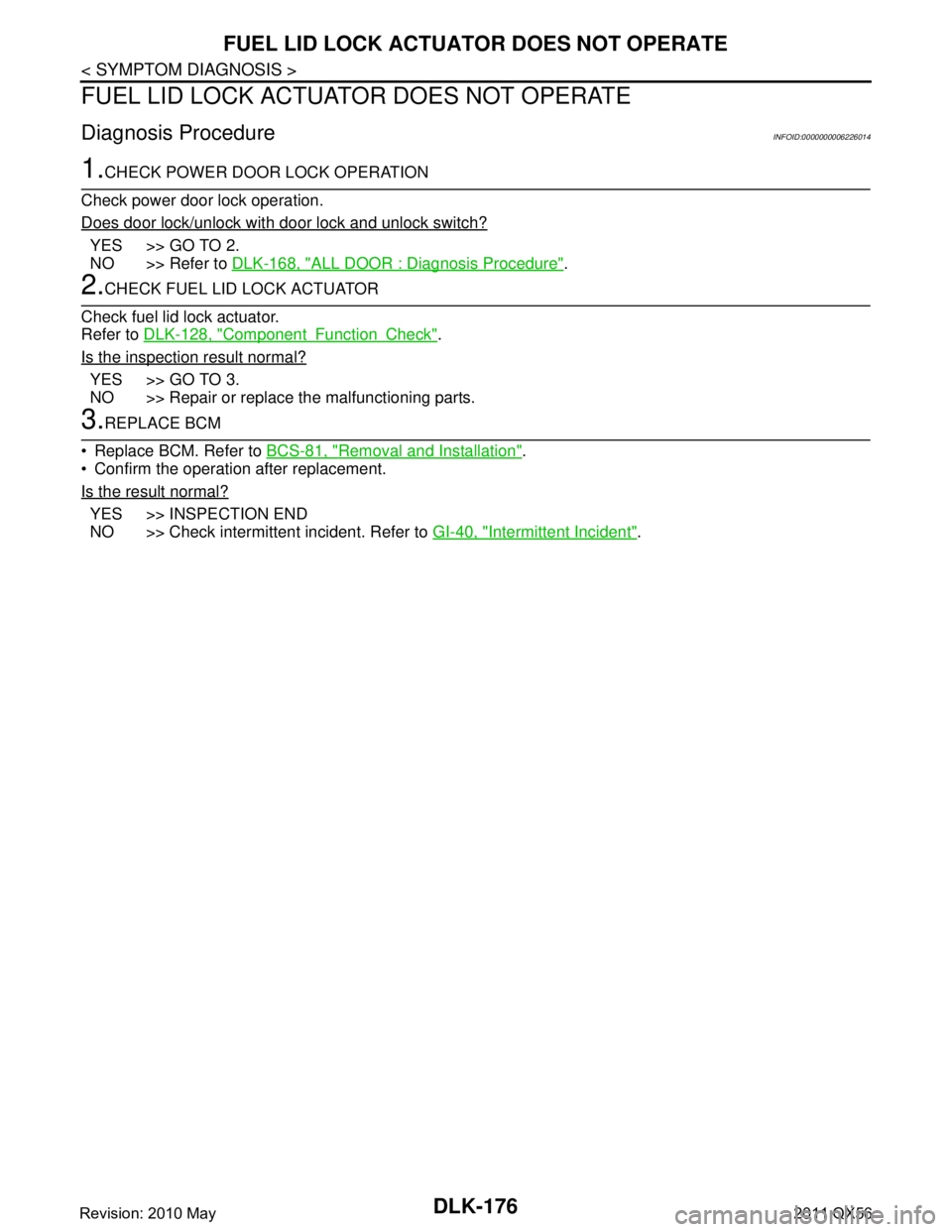
FUEL LID LOCK ACTUATOR DOES NOT OPERATE
Diagnosis ProcedureINFOID:0000000006226014
1.CHECK POWER DOOR LOCK OPERATION
Check power door lock operation.
Does door lock/unlock with door lock and unlock switch?
YES >> GO TO 2.
NO >> Refer to DLK-168, "
ALL DOOR : Diagnosis Procedure".
2.CHECK FUEL LID LOCK ACTUATOR
Check fuel lid lock actuator.
Refer to DLK-128, "
ComponentFunctionCheck".
Is the inspection result normal?
YES >> GO TO 3.
NO >> Repair or replace the malfunctioning parts.
3.REPLACE BCM
Replace BCM. Refer to BCS-81, "
Removal and Installation".
Confirm the operation after replacement.
Is the result normal?
YES >> INSPECTION END
NO >> Check intermittent incident. Refer to GI-40, "
Intermittent Incident".
Revision: 2010 May2011 QX56
Page 1784 of 5598
DLK-248
< REMOVAL AND INSTALLATION >
FUEL FILLER LID OPENER
FUEL FILLER LID OPENER
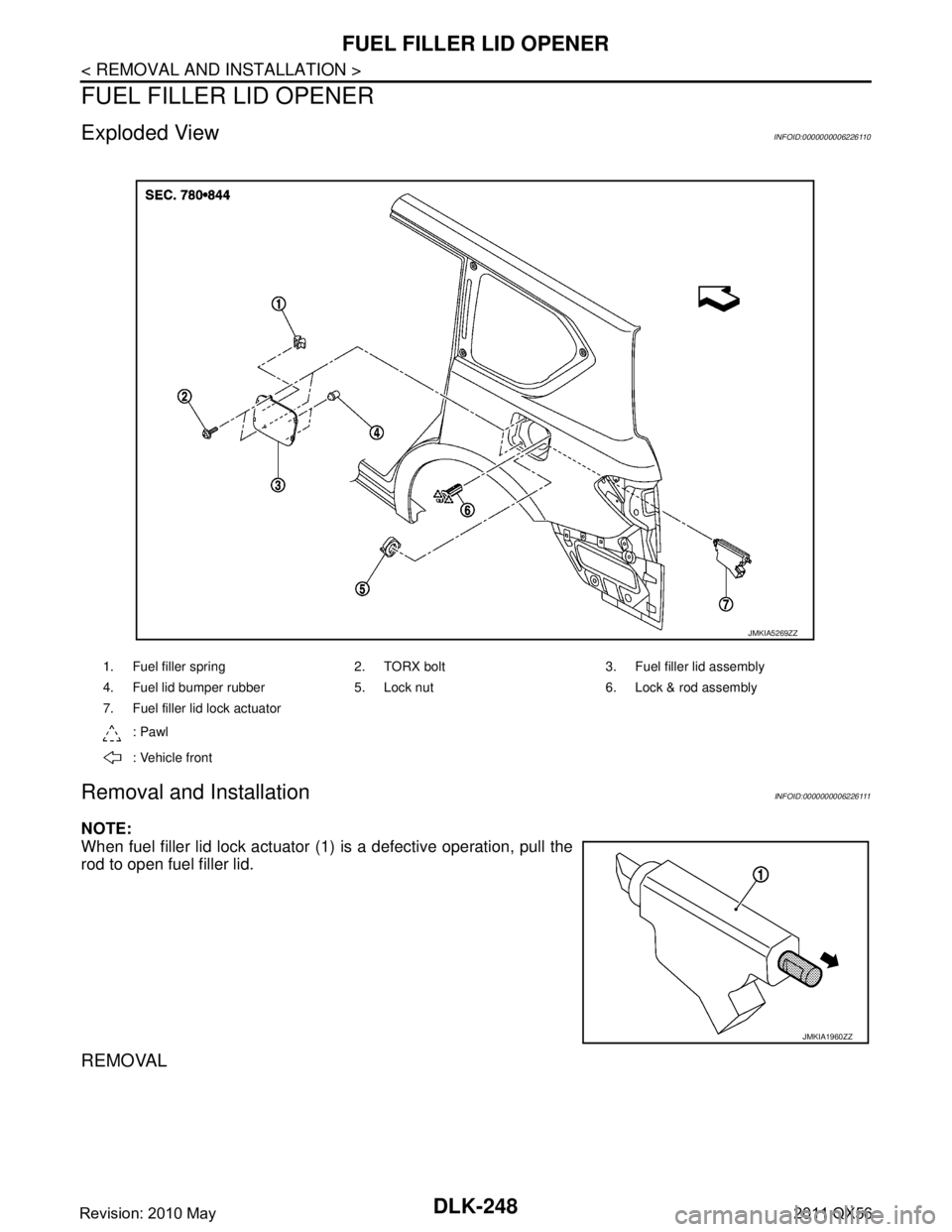
Exploded ViewINFOID:0000000006226110
Removal and InstallationINFOID:0000000006226111
NOTE:
When fuel filler lid lock actuator (1) is a defective operation, pull the
rod to open fuel filler lid.
REMOVAL
1. Fuel filler spring 2. TORX bolt 3. Fuel filler lid assembly
4. Fuel lid bumper rubber 5. Lock nut 6. Lock & rod assembly
7. Fuel filler lid lock actuator: Pawl
: Vehicle front
JMKIA5269ZZ
JMKIA1960ZZ
Revision: 2010 May2011 QX56
Page 1785 of 5598
FUEL FILLER LID OPENERDLK-249
< REMOVAL AND INSTALLATION >
C
DE
F
G H
I
J
L
M A
B
DLK
N
O P
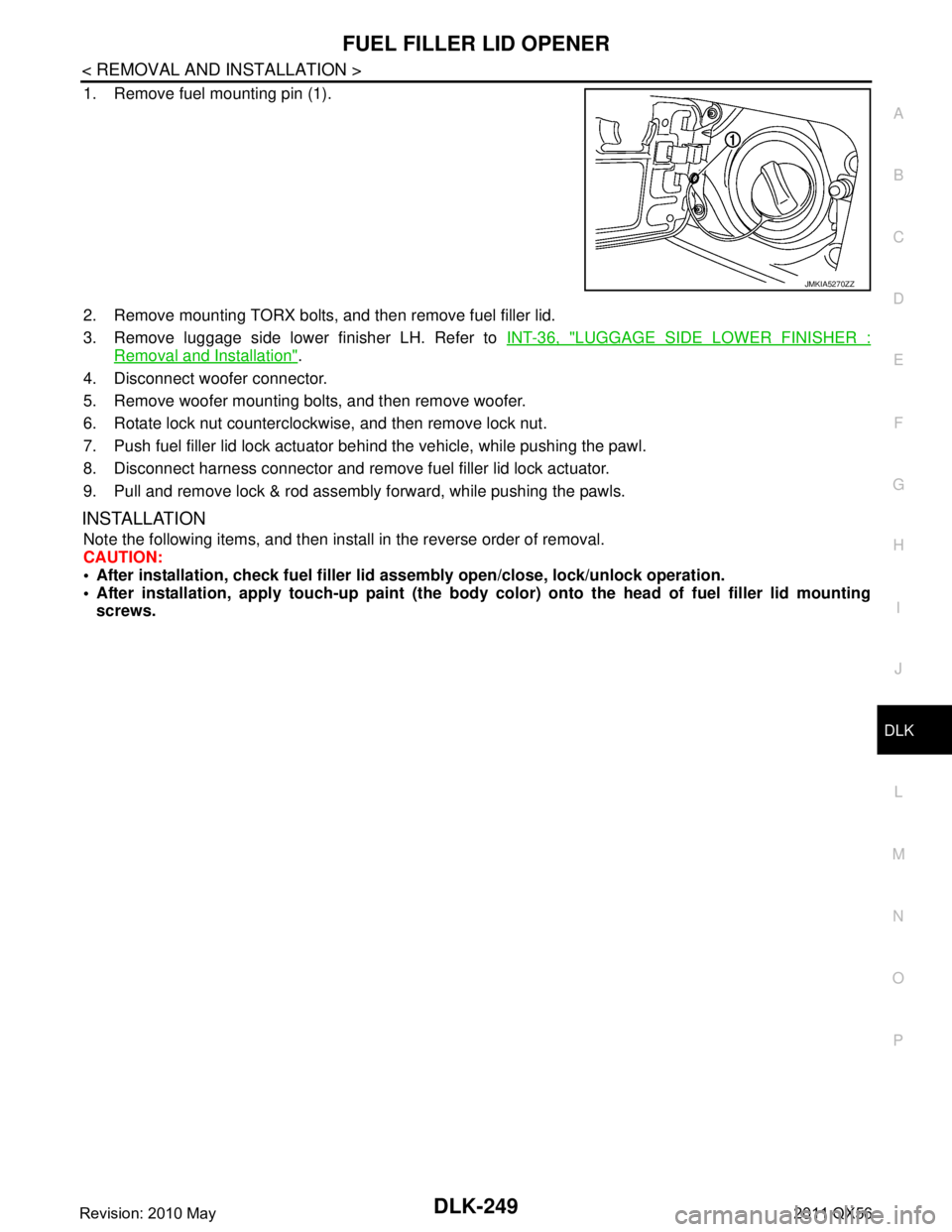
1. Remove fuel mounting pin (1).
2. Remove mounting TORX bolts, and then remove fuel filler lid.
3. Remove luggage side lower finisher LH. Refer to INT-36, "
LUGGAGE SIDE LOWER FINISHER :
Removal and Installation".
4. Disconnect woofer connector.
5. Remove woofer mounting bolts, and then remove woofer.
6. Rotate lock nut counterclockwise, and then remove lock nut.
7. Push fuel filler lid lock actuator behind the vehicle, while pushing the pawl.
8. Disconnect harness connector and remove fuel filler lid lock actuator.
9. Pull and remove lock & rod assembly forward, while pushing the pawls.
INSTALLATION
Note the following items, and then install in the reverse order of removal.
CAUTION:
After installation, check fuel filler li d assembly open/close, lock/unlock operation.
After installation, apply touch-up paint (the body color) onto the head of fuel filler lid mounting
screws.
JMKIA5270ZZ
Revision: 2010 May2011 QX56
Page 1788 of 5598
DLK-252
< REMOVAL AND INSTALLATION >
CAB MOUNTING INSULATOR
Drain brake fluid from brake line. Refer to BR-10, "Draining".
Release fuel pressure. Refer to EC-153, "
Work Procedure".
Disconnect both battery cables. Refer to PG-164, "
Removal and Installation".
Drain engine coolant from radiator. Refer to CO-8, "
Draining".
Discharge refrigerant from A/C circuit. Refer to HA-20, "
Recycle Refrigerant".
Drain power steering fluid from reservoir tank.
4. Remove parts relating to connection of body assembly and frame assembly. Tire and wheel: Refer to WT-64, "
Removal and Installation" (with TPMS).
Front fender protector (LH and RH): Refer to EXT-23, "
FENDER PROTECTOR : Removal and Installa-
tion".
Front bumper: Refer to EXT-13, "
Removal and Installation".
Radiator core support upper: Refer to DLK-220, "
Removal and Installation".
Fan shroud: Refer to CO-16, "
Removal and Installation".
Battery and battery case: Refer to PG-164, "
Removal and Installation".
Air cleaner case (upper and lower): Refer to EM-27, "
Removal and Installation".
Engine cover: Refer to EM-25, "
Removal and Installation".
Rear wheel house protector (LH and RH): EXT-24, "
REAR WHEEL HOUSE PROTECTOR : Removal
and Installation".
Rear bumper: Refer to EXT-17, "
Removal and Installation".
Fuel filler tube: Remove to FL-8, "
Exploded View".
Spare tire
Towing hook bracket.
5. Separate parts relating to connection of body assembly and frame assembly. Vehicle front
Disconnect ICC sensor connector. (models with ICC) Refer to CCS-176, "
Removal and Installation".
Remove radiator upper hose and radiator lower hose from radiator assembly. Refer to CO-13,
"Exploded View".
Remove A/T fluid cooler hose B and A/T fluid cooler hose E from A/T fluid cooler tubes. Refer to TM-
202, "Exploded View".
Remove power steering return hose from oil cooler, and then power steering return hose clamp bolt from frame assembly. Refer to ST-54, "
Exploded View".
Remove power steering suction hose from reservoir tank. Refer to ST-54, "
Exploded View".
CAUTION:
Never spill power steering fluid in engine room.
Remove A/C low-presser flexible hose from A/C low-presser pipe. Refer to HA-35, "
LOW-PRESSURE
FLEXIBLE HOSE : Removal and Installation".
Remove A/C hi-presser flexible hose from condenser. Refer to HA-34, "
HIGH-PRESSURE FLEXIBLE
HOSE : Removal and Installation".
Remove all engine Control Harness connectors, har ness clips and others that are connected to the
body assembly side of the engine room. (engine room LH and RH side). Refer to PG-148, "
Engine Con-
trol Harness".
NOTE:
Separate harness connectors from ECM (engine control module). Refer to EC-10, "
General Precau-
tions".
CAUTION:
When pulling out harnesses, never damage harnesses or connectors.
After temporarily securing connectors, cover th em with vinyl or similar material to protect
against adhesion of foreign materials.
Disconnect engine room harness connectors and remo ve harness clips from engine assembly (engine
RH side). Refer to PG-146, "
Engine Room Harness".
Remove heater hoses from front water outlet tube (engine room RH side). Refer to HA-33, "
Exploded
View".
Disconnect front wheel sensor connectors (LH and RH). Refer to BRC-134, "
FRONT WHEEL SENSOR
: Exploded View".
Disconnect fuel feed tube and EVAP hos e (front wheel well LH side).
Remove steering lower shaft from steering gear side assembly. Refer to ST-37, "
Removal and Installa-
tion"
CAUTION:
Spiral cable may be cut if steering wheel turns while separating steering column assembly and
steering gear assembly.
Revision: 2010 May2011 QX56
Page 1789 of 5598
CAB MOUNTING INSULATORDLK-253
< REMOVAL AND INSTALLATION >
C
DE
F
G H
I
J
L
M A
B
DLK
N
O P
Remove brake tube from connector (front wheel well LH and RH side). Refer to BR-22, "FRONT :
Exploded View"
Vehicle center side
Remove A/T control cable from manual lever. Refer to TM-178, "
Removal and Installation".
Separate parking brake rear cable (LH and RH) from parking brake front cable. Refer to PB-5, "
Removal
and Installation".
Remove engine room harness connector (frame assembly RH center side). Refer to PG-146, "
Engine
Room Harness"
- Remove harness connector protector.
- Disconnect chassis harness connector from engine room harness connector.
- Remove harness bracket bolt, and then remove engi ne room harness connector from frame assembly.
Vehicle rear side
Remove EVAP hose (canister side).
Remove rear final drive breather hose from air breather tube (body side). Refer to DLN-201, "
Removal
and Installation".
Disconnect body harness connector from chassis harness connectors (frame assembly LH rear side).
Refer to PG-150, "
Body Harness"
6. Set safety stand to frame assembly. Release arm of 2-pole lift.
7. Remove cab mounting insulator bolts.
8. Set arm of 2-pole lift to body side sill portion of body.
9. Slowly lift 2-pole lift.
CAUTION:
Check that there is no inte rference with the vehicle.
Check that all connection points are disconnected.
10. Remove cab mounting insulator.
INSTALLATION
Note the following items, and then install in the reverse order of removal.
CAUTION:
Before starting engine, check oil/fl uid levels including engine coolant and engine oil. If levels are
less than the required quantity, fill to the specified level. Refer to MA-10, "
Fluids and Lubricants".
Warm up engine thoroughly to check that there is no leakage of fuel, exhaust gases, or any oil/fluids
including engine oil and engine coolant.
Revision: 2010 May2011 QX56
Page 1816 of 5598
![INFINITI QX56 2011 Factory Owners Guide
DLN-14
< SYSTEM DESCRIPTION >[TRANSFER: ATX90A]
STRUCTURE AND OPERATION
DESCRIPTION
Ball ramp lever operates in the direction of main shaft axis according to rotation of actuator shaft and
presses INFINITI QX56 2011 Factory Owners Guide
DLN-14
< SYSTEM DESCRIPTION >[TRANSFER: ATX90A]
STRUCTURE AND OPERATION
DESCRIPTION
Ball ramp lever operates in the direction of main shaft axis according to rotation of actuator shaft and
presses](/img/42/57033/w960_57033-1815.png)
DLN-14
< SYSTEM DESCRIPTION >[TRANSFER: ATX90A]
STRUCTURE AND OPERATION
DESCRIPTION
Ball ramp lever operates in the direction of main shaft axis according to rotation of actuator shaft and
presses piston. Pressure is applied to each clutch and torque is transmitted.
Shift fork operates in the direction of main shaft axis according to rotation of actuator shaft and performs
engagement and disengagement to Hi-Lo sleeve and lock sleev e of main shaft. Mode is switched between
4H ⇔4L.
AUTO MODE
The optimum torque distribution is electronically performed for front and rear wheels according to road con-
ditions.
Stable start without wheel spin is possible on slippery road conditions, such as on a snowy road.
When road condition does not require 4WD driving, the st atus becomes close to rear wheel drive, which
results in better fuel efficiency and prov ides FR-like steering characteristics.
The vehicle cornering status is judged according to information from each sensor, and the optimum torque is
distributed to front wheels for prev enting tight-corner braking symptom.
NOTE:
When there is a difference of revolution speed between the front and rear wheel the shift occasionally changes
to direct 4-wheel driving conditions aut omatically. This is not a malfunction.
4H MODE
Torque distribution for front and rear wheels is fixed and stable start is achieved while driving on an rough,
sandy or snowy road.
4L MODE
Large traction force is obtained due to low gear. High running ability and escaping ability are achieved.
Switching from 4H mode to 4L mode is not possible w hen the vehicle is not stopped and A/T shift selector is
not in the neutral position.
TORQUE DISTRIBUTION DIAGRAM
JPDIE0256GB
Revision: 2010 May2011 QX56