air suspension INFINITI QX56 2011 Factory User Guide
[x] Cancel search | Manufacturer: INFINITI, Model Year: 2011, Model line: QX56, Model: INFINITI QX56 2011Pages: 5598, PDF Size: 94.53 MB
Page 1956 of 5598
![INFINITI QX56 2011 Factory User Guide
DLN-154
< SYMPTOM DIAGNOSIS >[FRONT FINAL DRIVE: R180A]
NOISE, VIBRATION AND HARSHNESS
(NVH) TROUBLESHOOTING
SYMPTOM DIAGNOSIS
NOISE, VIBRATION AND HARSHNESS (NVH) TROUBLESHOOTING
NVH Troubleshootin](/img/42/57033/w960_57033-1955.png "INFINITI QX56 2011 Factory User Guide
DLN-154
< SYMPTOM DIAGNOSIS >[FRONT FINAL DRIVE: R180A]
NOISE, VIBRATION AND HARSHNESS
(NVH) TROUBLESHOOTING
SYMPTOM DIAGNOSIS
NOISE, VIBRATION AND HARSHNESS (NVH) TROUBLESHOOTING
NVH Troubleshootin")
DLN-154
< SYMPTOM DIAGNOSIS >[FRONT FINAL DRIVE: R180A]
NOISE, VIBRATION AND HARSHNESS
(NVH) TROUBLESHOOTING
SYMPTOM DIAGNOSIS
NOISE, VIBRATION AND HARSHNESS (NVH) TROUBLESHOOTING
NVH Troubleshooting ChartINFOID:0000000006222377
Use the chart below to help you find the cause of the symptom. If necessa ry, repair or replace these parts.
×: ApplicableReference
DLN-174, "
Inspection
"
DLN-171, "
Adjustment
"
DLN-174, "
Inspection
"
DLN-171, "
Adjustment
"
DLN-171, "
Adjustment
"
DLN-155, "
Inspection
"
NVH of FRONT PROPELLER SHAFT in this section.
NVH of REAR PROPELLER SHAFT in this section.
NVH in FAX, RAX, FSU and RSU sections.
NVH in WT section.
NVH in WT section.
NVH in FAX and RAX section.
NVH in BR section.
NVH in ST section.
Possible cause and SUSPECTED PARTS
Gear tooth rough
Gear contact improper
Tooth surfaces worn
Backlash incorrect
Companion flange excessive runout
Gear oil improper
PROPELLER SHAFT
AXLE AND SUSPENSION
TIRE
ROAD WHEEL
DRIVE SHAFT
BRAKE
STEERING
Symptom Noise
×××××××××××××
Revision: 2010 May2011 QX56
Page 1994 of 5598
![INFINITI QX56 2011 Factory User Guide
DLN-192
< SYMPTOM DIAGNOSIS >[REAR FINAL DRIVE: R230]
NOISE, VIBRATION AND HARSHNESS
(NVH) TROUBLESHOOTING
SYMPTOM DIAGNOSIS
NOISE, VIBRATION AND HARSHNESS (NVH) TROUBLESHOOTING
NVH Troubleshooting](/img/42/57033/w960_57033-1993.png "INFINITI QX56 2011 Factory User Guide
DLN-192
< SYMPTOM DIAGNOSIS >[REAR FINAL DRIVE: R230]
NOISE, VIBRATION AND HARSHNESS
(NVH) TROUBLESHOOTING
SYMPTOM DIAGNOSIS
NOISE, VIBRATION AND HARSHNESS (NVH) TROUBLESHOOTING
NVH Troubleshooting")
DLN-192
< SYMPTOM DIAGNOSIS >[REAR FINAL DRIVE: R230]
NOISE, VIBRATION AND HARSHNESS
(NVH) TROUBLESHOOTING
SYMPTOM DIAGNOSIS
NOISE, VIBRATION AND HARSHNESS (NVH) TROUBLESHOOTING
NVH Troubleshooting ChartINFOID:0000000006222410
Use the chart below to find the cause of the symp tom. If necessary, repair or replace these parts.
×: ApplicableReference page
DLN-215, "
Inspection
"
DLN-210, "
Adjustment
"
DLN-215, "
Inspection
"
DLN-210, "
Adjustment
"
DLN-210, "
Adjustment
"
DLN-193, "
Inspection
"
NVH of FRONT PROPELLER SHAFT in this section.
NVH of REAR PROPELLER SHAFT in this section.
NVH in FAX, RAX, and RSU sections.
NVH in WT section.
NVH in WT section.
NVH in RAX section.
NVH in BR section.
NVH in ST section.
Possible cause and SUSPECTED PARTS
Gear tooth rough
Gear contact improper
Tooth surfaces worn
Backlash incorrect
Companion flange excessive runout
Gear oil improper
PROPELLER SHAFT
AXLE AND SUSPENSION
TIRES
ROAD WHEEL
DRIVE SHAFT
BRAKES
STEERING
Symptom Noise
×××××××××××××
Revision: 2010 May2011 QX56
Page 2906 of 5598
![INFINITI QX56 2011 Factory User Guide
FAX-6
< SYMPTOM DIAGNOSIS >[2WD]
NOISE, VIBRATION AND HARSHNESS
(NVH) TROUBLESHOOTING
SYMPTOM DIAGNOSIS
NOISE, VIBRATION AND HARSHNESS (NVH) TROUBLESHOOTING
NVH Troubleshooting ChartINFOID:000000000](/img/42/57033/w960_57033-2905.png "INFINITI QX56 2011 Factory User Guide
FAX-6
< SYMPTOM DIAGNOSIS >[2WD]
NOISE, VIBRATION AND HARSHNESS
(NVH) TROUBLESHOOTING
SYMPTOM DIAGNOSIS
NOISE, VIBRATION AND HARSHNESS (NVH) TROUBLESHOOTING
NVH Troubleshooting ChartINFOID:000000000")
FAX-6
< SYMPTOM DIAGNOSIS >[2WD]
NOISE, VIBRATION AND HARSHNESS
(NVH) TROUBLESHOOTING
SYMPTOM DIAGNOSIS
NOISE, VIBRATION AND HARSHNESS (NVH) TROUBLESHOOTING
NVH Troubleshooting ChartINFOID:0000000006225415
Use chart below to find the cause of the symptom. If necessary, repair or replace these parts.
×: ApplicableReference
FAX-8—
FAX-7
NVH in FAX and FSU sections
NVH in WT section
NVH in WT section
NVH in BR section
NVH in ST section
Possible cause and SUSPECTED PARTS
Improper installation, looseness
Parts interference
Wheel bearing damage
FRONT AXLE AND FRONT SUSPENSION
TIRE
ROAD WHEEL
BRAKE
STEERING
Symptom FRONT AXLE Noise
××××××××
Shake ××××××××
Vibration ××××× ×
Shimmy ×× ×××××
Judder × ×××××
Poor quality ride or handling ×× ×××
Revision: 2010 May2011 QX56
Page 2915 of 5598
![INFINITI QX56 2011 Factory User Guide
NOISE, VIBRATION AND HARSHNESS (NVH) TROUBLESHOOTINGFAX-15
< SYMPTOM DIAGNOSIS > [4WD]
C
EF
G H
I
J
K L
M A
B
FA X
N
O P
SYMPTOM DIAGNOSIS
NOISE, VIBRATION AND HARSHN ESS (NVH) TROUBLESHOOTING
NVH Tr](/img/42/57033/w960_57033-2914.png "INFINITI QX56 2011 Factory User Guide
NOISE, VIBRATION AND HARSHNESS (NVH) TROUBLESHOOTINGFAX-15
< SYMPTOM DIAGNOSIS > [4WD]
C
EF
G H
I
J
K L
M A
B
FA X
N
O P
SYMPTOM DIAGNOSIS
NOISE, VIBRATION AND HARSHN ESS (NVH) TROUBLESHOOTING
NVH Tr")
NOISE, VIBRATION AND HARSHNESS (NVH) TROUBLESHOOTINGFAX-15
< SYMPTOM DIAGNOSIS > [4WD]
C
EF
G H
I
J
K L
M A
B
FA X
N
O P
SYMPTOM DIAGNOSIS
NOISE, VIBRATION AND HARSHN ESS (NVH) TROUBLESHOOTING
NVH Troubleshooting ChartINFOID:0000000006225393
Use chart below to find the cause of the symptom. If necessary, repair or replace these parts.
×: ApplicableReference
—
FAX-28—
FAX-18—
FAX-16
NVH in FAX and FSU sections
Refer to FRONT AXLE in this chart.
NVH in WT section
NVH in WT section
Refer to DRIVE SHAFT in this chart.
NVH in BR section
NVH in ST section
Possible cause and SUSPECTED PARTS
Excessive joint angle
Joint sliding resistance
Imbalance
Improper installation, looseness
Parts interference
Wheel bearing damage
FRONT AXLE AND FRONT SUSPENSION
FRONT AXLE
TIRE
ROAD WHEEL
DRIVE SHAFT
BRAKE
STEERING
Symptom DRIVE
SHAFT
Noise
×× ××××× ××
Shake × × ××××× ××
FRONT
AXLE Noise
×××× ×××××
Shake ×××× ×××××
Vibration ×××× × × ×
Shimmy ×× × ×× ××
Judder × × ×× ××
Poor quality ride or handling ×× × ××
Revision: 2010 May2011 QX56
Page 2943 of 5598

FSU-1
SUSPENSION
C
DF
G H
I
J
K L
M
SECTION FSU
A
B
FSU
N
O PCONTENTS
FRONT SUSPENSION
PRECAUTION ................ ...............................2
PRECAUTIONS .............................................. .....2
Precaution for Supplemental Restraint System
(SRS) "AIR BAG" and "SEAT BELT PRE-TEN-
SIONER" ............................................................. ......
2
Precaution Necessary for Steering Wheel Rota-
tion after Battery Disconnect .....................................
2
Precaution for Procedure without Cowl Top Cover ......3
Precautions for Suspension ......................................3
PREPARATION ............................................4
PREPARATION .............................................. .....4
Special Service Tools .......................................... ......4
Commercial Service Tools ........................................4
SYMPTOM DIAGNOSIS ...............................5
NOISE, VIBRATION AND HARSHNESS
(NVH) TROUBLESHOOTING ........................ .....
5
NVH Troubleshooting Chart ................................ ......5
PERIODIC MAINTENANCE ..........................6
FRONT SUSPENSION ASSEMBLY .............. .....6
Inspection ............................................................ ......6
WHEEL ALIGNMENT ..........................................7
Inspection ............................................................ ......7
Adjustment ................................................................7
REMOVAL AND INSTALLATION ................9
FRONT COIL SPRING AND SHOCK AB-
SORBER ............................................................
9
Exploded View ..................................................... .....9
Removal and Installation .........................................10
Disassembly and Assembly .....................................11
Inspection and Adjustment ......................................12
Disposal ...................................................................13
LOWER LINK ....................................................14
Exploded View .........................................................14
Removal and Installation .........................................14
Inspection ................................................................15
UPPER LINK ......................... ............................17
Exploded View ..................................................... ....17
Removal and Installation .........................................17
Inspection ................................................................18
FRONT STABILIZER ........................................20
Exploded View .........................................................20
Removal and Installation .........................................20
Inspection ................................................................20
SERVICE DATA AND SPECIFICATIONS
(SDS) ............... .............................................
21
SERVICE DATA AND SPECIFICATIONS
(SDS) .................................................................
21
Wheel Alignment ................................................. ....21
Ball Joint ..................................................................21
Wheel Height ...........................................................21
Revision: 2010 May2011 QX56
Page 2945 of 5598
PRECAUTIONSFSU-3
< PRECAUTION >
C
DF
G H
I
J
K L
M A
B
FSU
N
O P
5. When the repair work is completed, re-connect both battery cables. With the brake pedal released, turn
the push-button ignition switch from ACC position to ON position, then to LOCK position. (The steering
wheel will lock when the push-button ignition switch is turned to LOCK position.)
6. Perform self-diagnosis check of a ll control units using CONSULT-III.
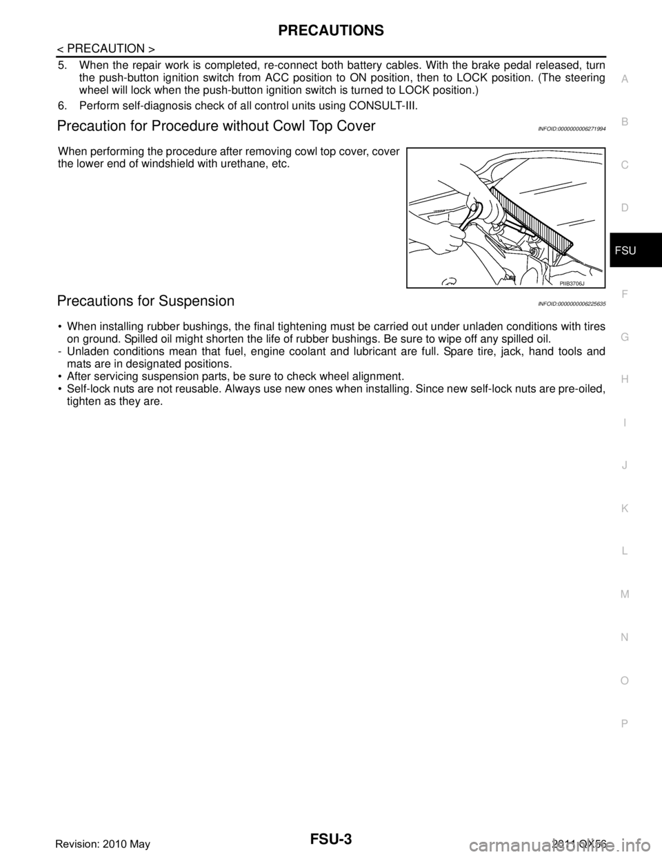
Precaution for Procedure without Cowl Top CoverINFOID:0000000006271994
When performing the procedure after removing cowl top cover, cover
the lower end of windshield with urethane, etc.
Precautions for SuspensionINFOID:0000000006225635
When installing rubber bushings, the final tightening mu st be carried out under unladen conditions with tires
on ground. Spilled oil might shorten the life of rubb er bushings. Be sure to wipe off any spilled oil.
- Unladen conditions mean that fuel, engine coolant and l ubricant are full. Spare tire, jack, hand tools and
mats are in designated positions.
After servicing suspension parts, be sure to check wheel alignment.
Self-lock nuts are not reusable. Always use new ones w hen installing. Since new self-lock nuts are pre-oiled,
tighten as they are.
PIIB3706J
Revision: 2010 May2011 QX56
Page 2947 of 5598
NOISE, VIBRATION AND HARSHNESS (NVH) TROUBLESHOOTINGFSU-5
< SYMPTOM DIAGNOSIS >
C
DF
G H
I
J
K L
M A
B
FSU
N
O P
SYMPTOM DIAGNOSIS
NOISE, VIBRATION AND HARSHN ESS (NVH) TROUBLESHOOTING
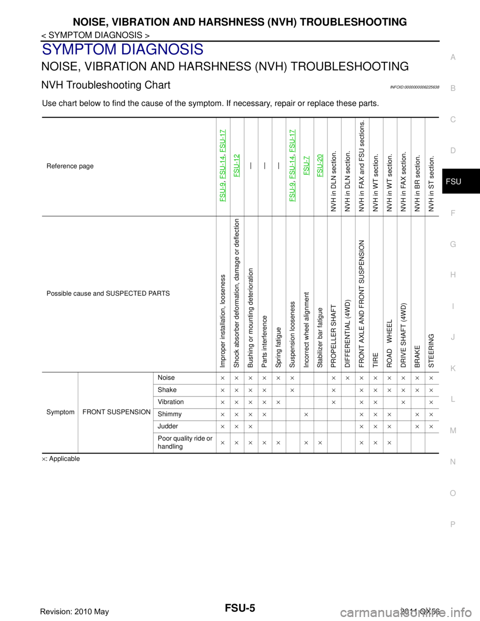
NVH Troubleshooting ChartINFOID:0000000006225638
Use chart below to find the cause of the symptom. If necessary, repair or replace these parts.
×: ApplicableReference page
FSU-9
,
FSU-14
, FSU-17
FSU-12
—
—
—
FSU-9
, FSU-14
, FSU-17
FSU-7FSU-20
NVH in DLN section.
NVH in DLN section.
NVH in FAX and FSU sections.
NVH in WT section.
NVH in WT section.
NVH in FAX section.
NVH in BR section.
NVH in ST section.
Possible cause and SUSPECTED PARTS
Improper installation, looseness
Shock absorber deformation, damage or deflection
Bushing or mounting deterioration
Parts interference
Spring fatigue
Suspension looseness
Incorrect wheel alignment
Stabilizer bar fatigue
PROPELLER SHAFT
DIFFERENTIAL (4WD)
FRONT AXLE AND FRONT SUSPENSION
TIRE
ROAD WHEEL
DRIVE SHAFT (4WD)
BRAKE
STEERING
Symptom FRONT SUSPENSION Noise
×××××× ××××××××
Shake ×××× × × ××××××
Vibration ××××× × ×× × ×
Shimmy ×××× × ××× ××
Judder ××× ××× ××
Poor quality ride or
handling ××××× ×× ×××
Revision: 2010 May2011 QX56
Page 2949 of 5598
WHEEL ALIGNMENTFSU-7
< PERIODIC MAINTENANCE >
C
DF
G H
I
J
K L
M A
B
FSU
N
O P
WHEEL ALIGNMENT
InspectionINFOID:0000000006225640
DESCRIPTION
Measure wheel alignment under unladen conditions.
NOTE:
“Unladen conditions” means that fuel, engine coolant, and lubricant are full. Spare tire, jack, hand tools and
mats are in designated positions.
PRELIMINARY CHECK
Check the following:
Tires for improper air pressure and wear
Road wheels for runout: Refer to WT-64, "
Inspection".
Wheel bearing axial end play: Refer to FA X - 7 , "
Inspection" (2WD), FAX-16, "Inspection" (4WD).
Lower link and upper link ball joint axial end play: Refer to FSU-15, "
Inspection" and FSU-18, "Inspection".
Shock absorber operation.
Each mounting part of axle and suspension for looseness and deformation
Lower link for cracks, deformation and other damage
Vehicle height (posture)
GENERAL INFORMATION AND RECOMMENDATIONS
A four-wheel thrust alignment should be performed.
- This type of alignment is recomm ended for any NISSAN/INFINITI vehicle.
- The four-wheel “thrust” process helps ensure that t he vehicle is properly aligned and the steering wheel is
centered.
- The alignment rack itself should be capable of accepting any NISSAN/INFINITI vehicle.
- The rack should be checked to ensure that it is level.
Make sure the machine is properly calibrated.
- Your alignment equipment should be regularly ca librated in order to give correct information.
- Check with the manufacturer of your specific equi pment for their recommended Service/Calibration Sched-
ule.
ALIGNMENT PROCESS
IMPORTANT:
Use only the alignment specificati ons listed in this Service Manual.
When displaying the alignment settings, many alignment machines use “indicators”: (Green/red, plus or
minus, Go/No Go). Never use these indicators.
- The alignment specifications programmed into your machine that operate these indicators may not be cor-
rect.
- This may result in an ERROR.
Some newer alignment machines are equipped with an optional “Rolling Compensation” method to “com-
pensate” the sensors (alignment targets or head units). Never use this “Rolling Compensation” method.
- Use the “Jacking Compensation Method”. After installi ng the alignment targets or head units, raise the vehi-
cle and rotate the wheels 1/2 turn both ways.
- See Instructions in the alignment machine you're using for more information on this.
AdjustmentINFOID:0000000006225641
CAMBER, CASTER
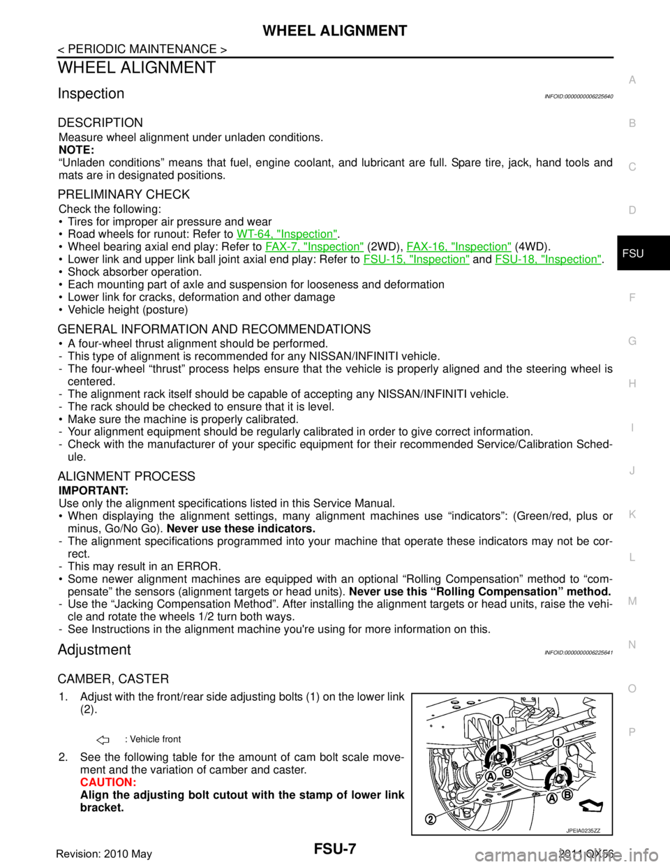
1. Adjust with the front/rear side adjusting bolts (1) on the lower link
(2).
2. See the following table for the amount of cam bolt scale move- ment and the variation of camber and caster.
CAUTION:
Align the adjusting bolt cutout with the stamp of lower link
bracket.
: Vehicle front
JPEIA0235ZZ
Revision: 2010 May2011 QX56
Page 3666 of 5598

OIL PUMPLU-13
< REMOVAL AND INSTALLATION >
C
DE
F
G H
I
J
K L
M A
LU
NP
O
OIL PUMP
Exploded ViewINFOID:0000000006289624
Removal and InstallationINFOID:0000000006289625
REMOVAL
NOTE:
Do not remove the engine assembly to perform this procedure.
1. Disconnect battery cable from
negative terminal. Refer to PG-165, "
Exploded View".
2. Drain engine oil. Refer to LU-8, "
Draining".
3. Drain engine coolant from radiator. Refer to CO-8, "
Draining".
CAUTION:
Perform this step when engine is cold.
Never spill engine coolant on drive belts.
4. Remove the following components and related parts: Air cleaner case assembly and air duct. Refer to EM-27, "
Exploded View".
Drive belt auto tensioner and idler pulley. Refer to EM-26, "
Exploded View".
Fan shroud. Refer to CO-13, "
Exploded View".
Cooling fan, fan coupling and fan bracket. Refer to CO-16, "
Exploded View".
Front under cover. Refer to EXT-25, "
Exploded View".
Protector A and B. Refer to SCS-32, "
FRONT TUBE ASSEMBLY : Exploded View".
Front suspension rear cross member. Refer to TM-205, "
2WD : Exploded View" (2WD models) or TM-
208, "4WD : Exploded View" (4WD models).
Steering gear assembly. Refer to ST-41, "
Exploded View".
Front final drive assembly. Refer to DLN-162, "
Exploded View".
Power steering oil pump. Refer to ST-48, "
Exploded View".
Alternator, alternator bracket and alternator stay. Refer to CHG-25, "
Exploded View".
Oil pan (lower) and oil strainer. Refer to EM-54, "
Exploded View".
Oil pan (upper). Refer to EM-57, "
Exploded View".
Electric throttle control actuator. Refer to EM-30, "
Exploded View".
Radiator hoses. Refer to CO-13, "
Exploded View".
Water suction hose and water suction pipe. Refer to CO-20, "
Exploded View".
Water pump pulley. Refer to CO-18, "
Exploded View".
Rocker cover. Refer to EM-33, "
Exploded View".
WBIA0415E
1. Oil pump body 2. Outer rotor 3. Inner rotor
4. Oil pump cover 5. Oil pump drive spacer 6. Regulator valve
7. Regulator spring 8. Regulator plug
Revision: 2010 May2011 QX56
Page 3678 of 5598

MA-8
< PERIODIC MAINTENANCE >
PERIODIC MAINTENANCE
NOTE:
(1) If towing a trailer, using a camper or a car-top carrier, or driving on rough or muddy roads, change (not just inspect) fluid /oil at every
30,000 miles (48,000 km) or 24 months.
(2) Automatic transmission fluid is maintenance-free.
(3) Refer to “Tire rotation” unde r the “General maintenance” heading earlier in this section.
Schedule 2INFOID:0000000006287731
EMISSION CONTROL SYSTEM
Abbreviations: R = Replace. I = Inspec t. Correct or replace if necessary. [ ]: At the mileage intervals only
Exhaust system I I I I MA-21
In-cabin microfilter R RVTL-17
MAINTENANCE OPERATIONMAINTENANCE INTERVAL
Reference
Section -
Page or - Con- tent Title
Perform at number of miles,
kilometers or months,
whichever comes first. Miles x 1,000
(km x 1,000)
Months 3.75
(6)
3 7.50
(12)
6 11 . 2 5
(18)
9 15
(24)
12 18.75
(30)
15 22.5
(36)
18 26.25
(42)
21 30
(48)
24
MAINTENANCE OPERATION MAINTENANCE INTERVAL
Reference
Section - Page
or - Content Title
Perform at number of miles,
kilometers or months,
whichever comes first. Miles x 1,000
(km x 1,000) Months 33.75
(54)27 37.5
(60) 30 41.25
(66)33 45
(72) 36 48.75
(78)39 52.5
(84) 42 56.25
(90)45 60
(96) 48
Brake lines & cables I I MA-28
Brake fluid R RMA-28
Brake pads & rotors I I I IMA-30
BR-16
BR-18
BR-16
BR-18
Transfer fluid & differential
gear oil
NOTE (1) I I MA-21MA-24
MA-25
Automatic transmission flu-
id
NOTE (2)
—
Steering gear & linkage,
axle & suspension parts IIII
MA-31
MA-32
Tire rotation NOTE (3) MA-4WT-63
Drive shaft boots and pro-
peller shaft (4WD models)IIII MA-33MA-22
MA-23
MA-23
Exhaust system I I I I
MA-21
In-cabin microfilter R RVTL-17
MAINTENANCE OPERATIONMAINTENANCE INTERVAL
Reference Sec-
tion - Page or -
Content Title
Perform at number of miles, kilo-
meters or months, whichever
comes first. Miles x 1,000
(km x 1,000)
Months 7.5
(12)
6 15
(24)
12 22.5
(36)
18 30
(48)
24 37.5
(60)
30 45
(72)
36 52.5
(84)
42 60
(96)
48
Drive belts NOTE (1) I* MA-12
Air cleaner filter [R] [R]MA-17
EVAP vapor lines I* I*MA-20
Fuel lines I* I*MA-17
Fuel filter NOTE (2) —
Engine coolant* NOTE (3) MA-13
Revision: 2010 May2011 QX56