instrument panel INFINITI QX56 2011 Factory Service Manual
[x] Cancel search | Manufacturer: INFINITI, Model Year: 2011, Model line: QX56, Model: INFINITI QX56 2011Pages: 5598, PDF Size: 94.53 MB
Page 1 of 5598

A
B
D
E
F
G
H
I
J
K
L
M
N
P
O
C
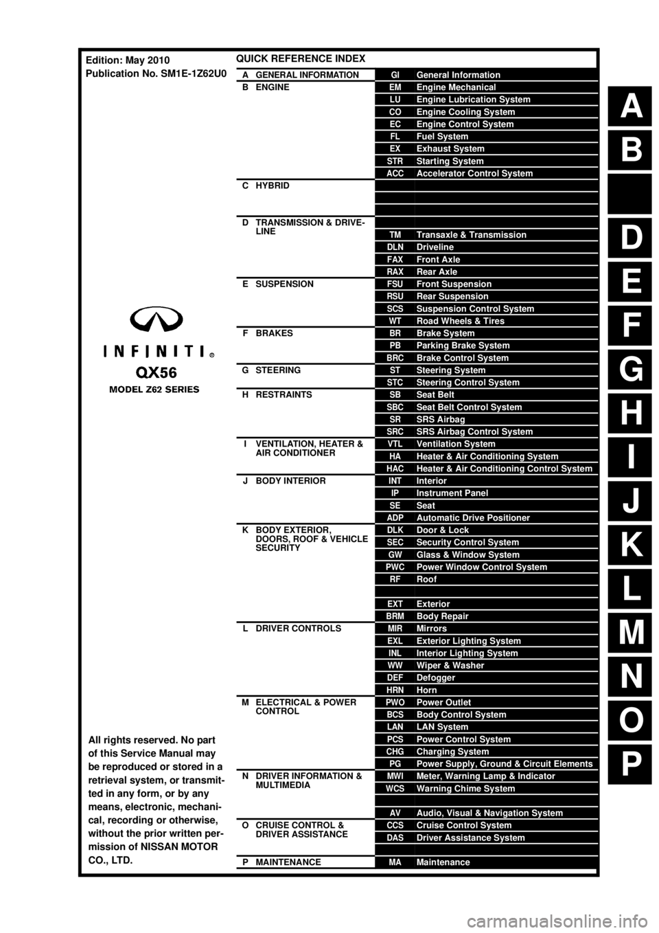
QUICK REFERENCE INDEX
AGENERAL INFORMATIONGIGeneral Information
BENGINEEMEngine Mechanical
LUEngine Lubrication System
COEngine Cooling System
ECEngine Control System
FLFuel System
EXExhaust System
STRStarting System
ACCAccelerator Control System
CHYBRIDHBCHybrid Control System
HBBHybrid Battery System
HBRHybrid Brake System
DTRANSMISSION & DRIVE-
LINECLClutch
TMTransaxle & Transmission
DLNDriveline
FAXFront Axle
RAXRear Axle
ESUSPENSIONFSUFront Suspension
RSURear Suspension
SCSSuspension Control System
WTRoad Wheels & Tires
FBRAKESBRBrake System
PBParking Brake System
BRCBrake Control System
GSTEERINGSTSteering System
STCSteering Control System
HRESTRAINTSSBSeat Belt
SBCSeat Belt Control System
SRSRS Airbag
SRCSRS Airbag Control System
IVENTILATION, HEATER &
AIR CONDITIONERVTLVentilation System
HAHeater & Air Conditioning System
HACHeater & Air Conditioning Control System
JBODY INTERIORINTInterior
IPInstrument Panel
SESeat
ADPAutomatic Drive Positioner
KBODY EXTERIOR,
DOORS, ROOF & VEHICLE
SECURITYDLKDoor & Lock
SECSecurity Control System
GWGlass & Window System
PWCPower Window Control System
RFRoof
HDHood
EXTExterior
BRMBody Repair
LDRIVER CONTROLSMIRMirrors
EXLExterior Lighting System
INLInterior Lighting System
WWWiper & Washer
DEFDefogger
HRNHorn
MELECTRICAL & POWER
CONTROLPWOPower Outlet
BCSBody Control System
LANLAN System
PCSPower Control System
CHGCharging System
PGPower Supply, Ground & Circuit Elements
NDRIVER INFORMATION &
MULTIMEDIAMWIMeter, Warning Lamp & Indicator
WCSWarning Chime System
SNSonar System
AVAudio, Visual & Navigation System
OCRUISE CONTROL &
DRIVER ASSISTANCECCSCruise Control System
DASDriver Assistance System
DMSDrive Mode System
PMAINTENANCEMAMaintenance
All rights reserved. No part
of this Service Manual may
be reproduced or stored in a
retrieval system, or transmit-
ted in any form, or by any
means, electronic, mechani-
cal, recording or otherwise,
without the prior written per-
mission of NISSAN MOTOR
CO., LTD.
Edition: May 2010
Publication No. SM1E-1Z62U0
Page 16 of 5598

COMPONENT PARTSADP-7
< SYSTEM DESCRIPTION >
C
DE
F
G H
I
K L
M A
B
ADP
N
O P
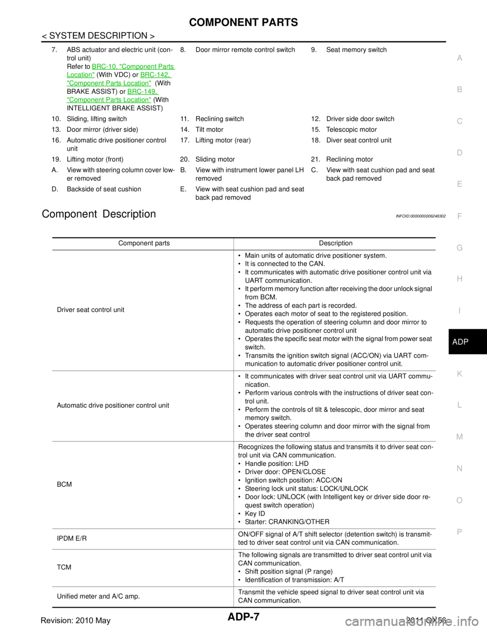
Component DescriptionINFOID:0000000006248302
7. ABS actuator and electric unit (con- trol unit)
Refer to BRC-10, "
Component Parts
Location" (With VDC) or BRC-142,
"Component Parts Location" (With
BRAKE ASSIST) or BRC-149,
"Component Parts Location" (With
INTELLIGENT BRAKE ASSIST) 8. Door mirror remote
control switch 9. Seat memory switch
10. Sliding, lifting switch 11. Reclining switch 12. Driver side door switch
13. Door mirror (driver side) 14. T ilt motor 15. Telescopic motor
16. Automatic drive positioner control unit 17. Lifting motor (rear) 18.
Diver seat control unit
19. Lifting motor (front) 20. Sliding motor 21. Reclining motor
A. View with steering column cover low- er removed B. View with instrument lower panel LH
removed C. View with seat cushion pad and seat
back pad removed
D. Backside of seat cushion E. View with seat cushion pad and seat back pad removed
Component parts Description
Driver seat control unit Main units of automatic drive positioner system.
It is connected to the CAN.
It communicates with automatic drive positioner control unit via
UART communication.
It perform memory function after receiving the door unlock signal
from BCM.
The address of each part is recorded.
Operates each motor of seat to the registered position.
Requests the operation of steering column and door mirror to automatic drive positioner control unit
Operates the specific seat motor with the signal from power seat
switch.
Transmits the ignition switch signal (ACC/ON) via UART com- munication to automatic driver positioner control unit.
Automatic drive positioner control unit It communicates with driver seat control unit via UART commu-
nication.
Perform various controls with the instructions of driver seat con- trol unit.
Perform the controls of tilt & telescopic, door mirror and seat memory switch.
Operates steering column and door mirror with the signal from the driver seat control
BCM Recognizes the following status and transmits it to driver seat con-
trol unit via CAN communication.
Handle position: LHD
Driver door: OPEN/CLOSE
Ignition switch position: ACC/ON
Steering lock unit status: LOCK/UNLOCK
Door lock: UNLOCK (with Intelligent key or driver side door re-
quest switch operation)
Key ID
Starter: CRANKING/OTHER
IPDM E/R ON/OFF signal of A/T shift selector (detention switch) is transmit-
ted to driver seat control unit via CAN communication.
TCM The following signals are transmitted to driver seat control unit via
CAN communication.
Shift position signal (P range)
Identification of transmission: A/T
Unified meter and A/C amp. Transmit the vehicle speed signal to driver seat control unit via
CAN communication.
Revision: 2010 May2011 QX56
Page 63 of 5598

ADP-54
< BASIC INSPECTION >
INSPECTION AND ADJUSTMENT
INTELLIGENT KEY INTERLOCK STORING : Description
INFOID:0000000006248332
Always perform the Intelligent Key interlock function st orage when the battery terminal is disconnected or the
driver seat control unit is replaced. The Intelligent Key interlock function will not operate normally if no memory
storage is performed.
INTELLIGENT KEY INTERLOCK STORIN G : Special Repair RequirementINFOID:0000000006248333
Intelligent Key Interlock Storage Procedure
Performing the following operation associates the regist ered driving position with Intelligent Key. When driver
door unlock operation is performed by Intelligent Key or driver door request switch, display of the registered
driving position and turnout operation can be performed.
1.STEP 1
Check the following conditions.
Ignition switch: OFF
Initialization: done
Driving position: registered
>> GO TO 2.
2.STEP 2
1. Push set switch. NOTE:
Memory indicator for which driver seat position is already retained in memory is illuminated for 5 seconds.
2. Push the Intelligent Key unlock button within 5 seconds after pushing memory switch (while the memory indicator is turned ON).
NOTE:
From the time registration is performed, the app licable memory indicator blinks for 5 seconds.
>> GO TO 3.
3.STEP 3
Confirm the operation of each part with memory operation and Intelligent Key interlock operation.
>> END
SYSTEM SETTING
SYSTEM SETTING : DescriptionINFOID:0000000006248334
The settings of the automatic driv ing positioner system can be changed, us ing CONSULT-III, the display unit
in the center of the instrument panel and the set s witch. Always check the settings before and after discon-
necting the battery terminal or replacing driver seat control unit.
Setting Change
× : Applicable
Item Content CON-
SULT
–III Display
Set
switch Factory
setting
Amount of seat sliding for
entry/exit assist The amount of seat sliding for entry/exit assist can
be selected from 3 items.
[40 mm/80 mm/150 mm]
x——40 mm
Entry/exit assist
(seat) Entry/exit assist (seat) can be selected:
ON (operated) – OFF (not operated)
xx
xON
Entry/exit assist
(steering column) Entry/exit assist (steering column) can be selected:
ON (operated) – OFF (not operated)
xx ON
Revision: 2010 May2011 QX56
Page 145 of 5598

ADP-136
< REMOVAL AND INSTALLATION >
AUTOMATIC DRIVE POSITIONER CONTROL UNIT
AUTOMATIC DRIVE POSITIONER CONTROL UNIT
Removal and InstallationINFOID:0000000006248442
REMOVAL
CAUTION:
When removing and installing, use shop cloths to protect parts from damage.
1. Remove instrument lower panel LH. Refer to IP-14, "
Removal
and Installation".
2. Remove screws (A).
3. Remove automatic drive positioner control unit (1).
INSTALLATION
Install in the reverse order of removal.
CAUTION:
Be sure to clump the harness to the right place.
NOTE:
After installing the driver seat, perform additional service when replacing control unit. Refer to ADP-51, "
ADDI-
TIONAL SERVICE WHEN REPLACING CONTROL UNIT : Description".
JMJIA1388ZZ
Revision: 2010 May2011 QX56
Page 158 of 5598

AV-10
< SYSTEM DESCRIPTION >
COMPONENT PARTS
Component Description
INFOID:0000000006216214
1. Squawker RH 2. Center speaker 3. Corner sensor front RH
4. Squawker LH 5. Front camera 6. Corner sensor front LH
7. Side camera LH 8. Front door speaker LH 9. Headrest display unit LH
10. Rear door tweeter LH 11. Rear door speaker LH 12. Roof speaker LH
13. Woofer 14. Corner sensor rear LH 15. Satellite radio antenna
16. Rear camera 17. Corner sensor rear RH 18. BOSE amp.
19. Roof speaker RH 20. Antenna amp. 21. Rear door speaker RH
22. Rear door tweeter RH 23. Headrest display unit RH 24. Front door speaker RH
25. Side camera RH and infrared LED
(auxiliary lighting) 26. Front display unit 27. Steering switch
28. Sonar control unit 29. Steering angle sensor 30. Preset switch
31. Around view monitor control unit 32. USB connector 33. Front auxiliary input jacks
34. Rear auxiliary input jacks 35. AV control unit 36. Video distributor
37. Multifunction switch 38. GPS antenna 39. Microphone A. Luggage side lower finisher LH re-
moved condition B.Luggage side lower finisher RH re-
moved condition C.Headlining assembly removed condi-
tion
D. Instrument lower
panel LH removed
condition E. Spiral cable part F. Cluste
r lid C removed condition
G. Within center console H. Instrument panel rear side
Part name Description
AV control unit Integrates hard disk drive (HDD) allowing map data and music data to be stored.
It is the master unit of the MULTI AV system, and it is connected to each control
unit by communication. It operates each system according to communication sig-
nals from the AV control unit.
The AV control unit includes the audio, hands-free phone, navigation, USB con- nection, DVD play and vehicle information functions.
It is connected to ECM and combination meter via CAN communication to obtain
necessary information for the vehicle information function.
It inputs the illumination signals that are required for the front display dimming con- trol.
It inputs the signals for driving status recognition (vehicle speed, reverse and park- ing brake).
The RGB digital image signal and composite image signal are output to front dis-
play unit.
Switches image and sound output to video distributor, inputting image switch sig- nal from headrest display unit via AV communication.
Amp. ON signal and mode change signal transmitted to BOSE amp.
Update of map data is performed with the DVD-ROM.
Front display unit Front display image is controlled by the serial communication from AV control unit.
RGB digital image signal is input from AV control unit.
Composite image signal is input from AV control unit.
Camera image signal is input from around view monitor control unit.
Touch panel function can be operated for each system by touching a display di-
rectly.
Headrest display unit Composite image signal [USB (video data), DVD and auxiliary input images] is in-
put from the video distributor.
It receives the DVD/AUX/USB sound signal from the video distributor, and then transmits it to the headphones.
Outputs image switch signal to video distributor via hard wire, according to rear seat remote controller operation.
Outputs image switch signal to AV control unit via AV communication, according to
rear seat remote controller operation.
Revision: 2010 May2011 QX56
Page 380 of 5598

AV-232
< REMOVAL AND INSTALLATION >
GPS ANTENNA
GPS ANTENNA
Removal and InstallationINFOID:0000000006216397
REMOVAL
1. Remove instrument panel. Refer to IP-13, "Exploded View".
2. Remove GPS antenna feeder clips.
3. Remove GPS antenna mounting screws to remove GPS antenna.
INSTALLATION
Install in the reverse order of removal.
Revision: 2010 May2011 QX56
Page 386 of 5598

AV-238
< REMOVAL AND INSTALLATION >
SONAR CONTROL UNIT
SONAR CONTROL UNIT
Removal and InstallationINFOID:0000000006216404
REMOVAL
1. Remove instrument lower panel LH. Refer to IP-13, "Exploded View".
2. Remove sonar control unit mounting screws.
3. Disconnect sonar control unit connector to remove sonar control unit.
INSTALLATION
Install in the reverse order of removal.
Revision: 2010 May2011 QX56
Page 478 of 5598

BR-8
< PERIODIC MAINTENANCE >
BRAKE PEDAL
Brake Pedal Height
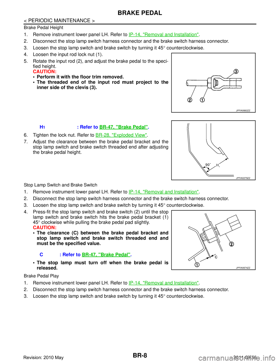
1. Remove instrument lower panel LH. Refer to IP-14, "Removal and Installation".
2. Disconnect the stop lamp switch harness c onnector and the brake switch harness connector.
3. Loosen the stop lamp switch and brake switch by turning it 45 ° counterclockwise.
4. Loosen the input rod lock nut (1).
5. Rotate the input rod (2), and adjust the brake pedal to the speci- fied height.
CAUTION:
Perform it with the floor trim removed.
The threaded end of the in put rod must project to the
inner side of the clevis (3).
6. Tighten the lock nut. Refer to BR-28, "
Exploded View".
7. Adjust the clearance between the brake pedal bracket and the stop lamp switch and brake switch threaded end after adjusting
the brake pedal height.
Stop Lamp Switch and Brake Switch
1. Remove instrument lower panel LH. Refer to IP-14, "Removal and Installation".
2. Disconnect the stop lamp switch harness c onnector and the brake switch harness connector.
3. Loosen the stop lamp switch and brake switch by turning it 45 ° counterclockwise.
4. Press-fit the stop lamp switch and brake switch (2) until the stop
lamp switch and brake switch hits the brake pedal bracket (1)
45 ° clockwise while pulling the brake pedal pad slightly.
CAUTION:
The clearance (C) between the brake pedal bracket and
stop lamp switch and brake switch threaded end and
must be the specified value.
The stop lamp must turn off when the brake pedal is released.
Brake Pedal Play
1. Remove instrument lower panel LH. Refer to IP-14, "Removal and Installation".
2. Disconnect the stop lamp switch harness c onnector and the brake switch harness connector.
3. Loosen the stop lamp switch and brake switch by turning it 45 ° counterclockwise.
JPFIA0662ZZ
H1: Refer to BR-47, "Brake Pedal".
JPFIA0279ZZ
C : Refer to BR-47, "Brake Pedal".
JPFIA0674ZZ
Revision: 2010 May2011 QX56
Page 490 of 5598

BR-20
< REMOVAL AND INSTALLATION >
BRAKE PEDAL
REMOVAL AND INSTALLATION
BRAKE PEDAL
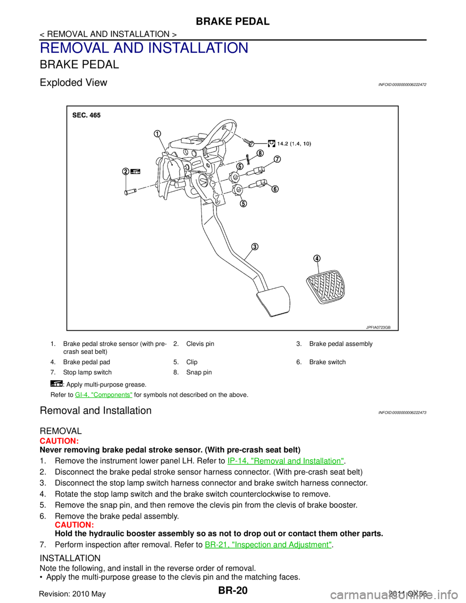
Exploded ViewINFOID:0000000006222472
Removal and InstallationINFOID:0000000006222473
REMOVAL
CAUTION:
Never removing brake pedal stroke sensor. (With pre-crash seat belt)
1. Remove the instrument lower panel LH. Refer to IP-14, "
Removal and Installation".
2. Disconnect the brake pedal stroke sensor har ness connector. (With pre-crash seat belt)
3. Disconnect the stop lamp switch harness connector and brake switch harness connector.
4. Rotate the stop lamp switch and the brake switch counterclockwise to remove.
5. Remove the snap pin, and then remove the clevis pin from the clevis of brake booster.
6. Remove the brake pedal assembly. CAUTION:
Hold the hydraulic booster assembly so as not to drop out or contact them other parts.
7. Perform inspection after removal. Refer to BR-21, "
Inspection and Adjustment".
INSTALLATION
Note the following, and install in the reverse order of removal.
Apply the multi-purpose grease to the clevis pin and the matching faces.
1. Brake pedal stroke sensor (with pre-
crash seat belt) 2. Clevis pin 3. Brake pedal assembly
4. Brake pedal pad 5. Clip 6. Brake switch
7. Stop lamp switch 8. Snap pin : Apply multi-purpose grease.
Refer to GI-4, "
Components" for symbols not described on the above.
JPFIA0723GB
Revision: 2010 May2011 QX56
Page 660 of 5598
![INFINITI QX56 2011 Factory Service Manual
COMPONENT PARTSBRC-143
< SYSTEM DESCRIPTION > [BRAKE ASSIST (WITH PREVIEW FUNCTION)]
C
D
E
G H
I
J
K L
M A
B
BRC
N
O P
Component DescriptionINFOID:0000000006248457
× : Applicable
13. Steering angle INFINITI QX56 2011 Factory Service Manual
COMPONENT PARTSBRC-143
< SYSTEM DESCRIPTION > [BRAKE ASSIST (WITH PREVIEW FUNCTION)]
C
D
E
G H
I
J
K L
M A
B
BRC
N
O P
Component DescriptionINFOID:0000000006248457
× : Applicable
13. Steering angle](/img/42/57033/w960_57033-659.png)
COMPONENT PARTSBRC-143
< SYSTEM DESCRIPTION > [BRAKE ASSIST (WITH PREVIEW FUNCTION)]
C
D
E
G H
I
J
K L
M A
B
BRC
N
O P
Component DescriptionINFOID:0000000006248457
× : Applicable
13. Steering angle sensor
Refer to BRC-10, "
Component Parts
Location"
14. ADAS control unit
Refer to DAS-13, "
Component Parts
Location"
A. Back side of engine room (RH) B. Front bumper (center) C. Upper side of brake pedal
D. Under side of instrument lower driver
panel
Component Function
Description
Vehicle-to-vehicle distance control mode
Conventional (fixed speed) cruise control mode Intelligent Brake Assist (IBA)
Brake Assist (with preview function)
ADAS control unit ×××× ADAS control unit calculates a target distance between vehicles
and a target speed, based on signals received from each sensor
and switch to transmit an engine torque command value to ECM
and a brake fluid pressure cont rol signal to ABS actuator and
electric unit (control unit) via CAN communication
ADAS control unit transmits buzzer output signal to combination
meter via CAN communication
ICC sensor ×××× ICC sensor detects light reflected from a vehicle ahead by irra-
diating laser forward and calculates a distance from the vehicle
ahead and a relative speed, based on the detected signal
ICC sensor transmits the presence/absence of vehicle ahead and the distance from the vehicle to ADAS control unit via ITS
communication
ECM ×××× ECM transmits the accelerator pedal position signal, ICC brake
switch signal, stop lamp switch signal, ICC steering switch sig-
nal, etc. to ADAS control unit via CAN communication
ECM controls the electric throttle control actuator based on the engine torque demand received from the ADAS control unit via
CAN communication
ABS actuator and electric unit
(control unit) ×××× ABS actuator and electric unit (c
ontrol unit) transmits the vehicle
speed signal (wheel speed), stop lamp signal and VDC/TCS/
ABS system operation condition to ADAS control unit via CAN
communication
ABS actuator and electric unit (c ontrol unit) controls the brake,
based on a brake fluid pressure control signal received from the
ADAS control unit via CAN communication
BCM ×BCM transmits the front wiper request signal to ADAS control unit
via CAN communication
TCM ××TCM transmits the signal related to A/T control to ADAS control
unit via CAN communication
Revision: 2010 May2011 QX56