recommended oil INFINITI QX56 2011 Factory User Guide
[x] Cancel search | Manufacturer: INFINITI, Model Year: 2011, Model line: QX56, Model: INFINITI QX56 2011Pages: 5598, PDF Size: 94.53 MB
Page 2567 of 5598
PRECAUTIONSEM-5
< PRECAUTION >
C
DE
F
G H
I
J
K L
M A
EM
NP
O
Avoid damaging sliding or mating surfaces. Completely re
move foreign materials such as cloth lint or dust.
Before assembly, oil sliding surfaces well.
Release air within route when refilling after draining engine coolant.
After repairing, start engine and increase engine speed to check engine coolant, fuel, engine oil, and
exhaust gases for leakage.
Parts Requiring Angle TighteningINFOID:0000000006289515
Use angle wrench [SST: KV10112100 (BT8653-A)] for the final tightening of the following engine parts:
- Cylinder head bolts
- Main bearing cap bolts
- Main bearing cap sub bolts
- Connecting rod cap bolts
- Crankshaft pulley bolt (No angle wrench is required as the bolt flange is provided with notches for angletightening)
Ensure thread and seat surfaces are clean and coated with engine oil.
Precaution for Liquid GasketINFOID:0000000006289516
REMOVAL OF LIQUID GASKET SEALING
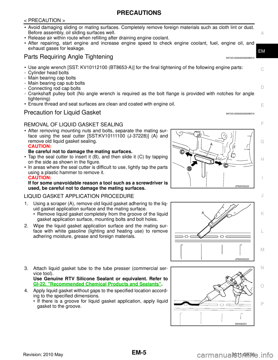
After removing mounting nuts and bolts, separate the mating sur- face using the seal cutter [SST:KV10111100 (J-37228)] (A) and
remove old liquid gasket sealing.
CAUTION:
Be careful not to damage the mating surfaces.
Tap the seal cutter to insert it (B), and then slide it (C) by tapping on the side as shown in the figure.
In areas where the seal cutter is difficult to use, lightly tap the parts using a plastic hammer to remove it.
CAUTION:
If for some unavoidable reason a tool such as a screwdriver is
used, be careful not to damage the mating surfaces.
LIQUID GASKET APPLICATION PROCEDURE
1. Using a scraper (A), remove old liquid gasket adhering to the liq- uid gasket application surface and the mating surface.
Remove liquid gasket completely from the groove of the liquidgasket application surface, mounting bolts and bolt holes.
2. Wipe the liquid gasket application surface and the mating sur- face with white gasoline (lighting and heating use) to remove
adhering moisture, grease and foreign materials.
3. Attach liquid gasket tube to the tube presser (commercial ser- vice tool).
Use Genuine RTV Silicone Seal ant or equivalent. Refer to
GI-22, "
Recommended Chemical Products and Sealants".
4. Apply liquid gasket without gaps to the specified location accord- ing to the specified dimensions.
If there is a groove for liquid gasket application, apply liquidgasket to the groove.
JPBIA0052ZZ
JPBIA0053ZZ
EMA0622D
Revision: 2010 May2011 QX56
Page 2596 of 5598
EM-34
< REMOVAL AND INSTALLATION >
ROCKER COVER
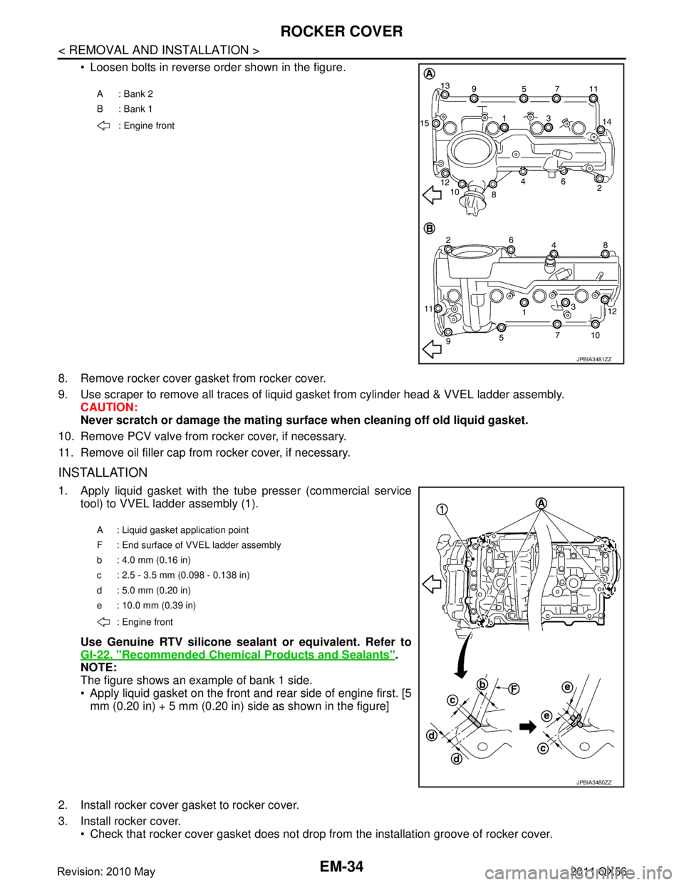
Loosen bolts in reverse order shown in the figure.
8. Remove rocker cover gasket from rocker cover.
9. Use scraper to remove all traces of liquid gasket from cylinder head & VVEL ladder assembly.
CAUTION:
Never scratch or damage the mating su rface when cleaning off old liquid gasket.
10. Remove PCV valve from rocker cover, if necessary.
11. Remove oil filler cap from rocker cover, if necessary.
INSTALLATION
1. Apply liquid gasket with the tube presser (commercial service tool) to VVEL ladder assembly (1).
Use Genuine RTV silicone seal ant or equivalent. Refer to
GI-22, "
Recommended Chemical Products and Sealants".
NOTE:
The figure shows an example of bank 1 side.
Apply liquid gasket on the front and rear side of engine first. [5 mm (0.20 in) + 5 mm (0.20 in) side as shown in the figure]
2. Install rocker cover gasket to rocker cover.
3. Install rocker cover. Check that rocker cover gasket does not drop fr om the installation groove of rocker cover.
A: Bank 2
B: Bank 1
: Engine front
JPBIA3481ZZ
A : Liquid gasket application point
F : End surface of VVEL ladder assembly
b : 4.0 mm (0.16 in)
c : 2.5 - 3.5 mm (0.098 - 0.138 in)
d : 5.0 mm (0.20 in)
e : 10.0 mm (0.39 in)
: Engine front
JPBIA3480ZZ
Revision: 2010 May2011 QX56
Page 2618 of 5598
EM-56
< REMOVAL AND INSTALLATION >
OIL PAN (LOWER) AND OIL STRAINER
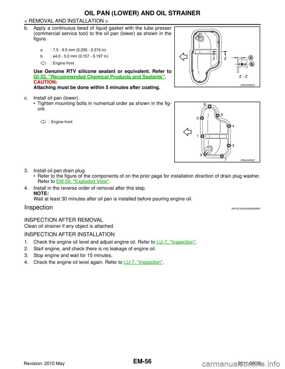
b. Apply a continuous bead of liquid gasket with the tube presser(commercial service tool) to the oil pan (lower) as shown in the
figure.
Use Genuine RTV silicone seal ant or equivalent. Refer to
GI-22, "
Recommended Chemical Products and Sealants".
CAUTION:
Attaching must be done with in 5 minutes after coating.
c. Install oil pan (lower). Tighten mounting bolts in numerical order as shown in the fig-ure.
3. Install oil pan drain plug. Refer to the figure of the components of on the prior page for installation direction of drain plug washer.Refer to EM-54, "
Exploded View".
4. Install in the reverse order of removal after this step. NOTE:
Wait at least 30 minutes after oil pan is installed before pouring engine oil.
InspectionINFOID:0000000006289561
INSPECTION AFTER REMOVAL
Clean oil strainer if any object is attached.
INSPECTION AFTER INSTALLATION
1. Check the engine oil level and adjust engine oil. Refer to LU-7, "Inspection".
2. Start engine, and check there is no leakage of engine oil.
3. Stop engine and wait for 15 minutes.
4. Check the engine oil level again. Refer to LU-7, "
Inspection".
a : 7.5 - 9.5 mm (0.295 - 0.374 in)
b: φ4.0 - 5.0 mm (0.157 - 0.197 in)
: Engine front
JPBIA3496ZZ
: Engine front
JPBIA3495ZZ
Revision: 2010 May2011 QX56
Page 2621 of 5598

OIL PAN (UPPER)EM-59
< REMOVAL AND INSTALLATION >
C
DE
F
G H
I
J
K L
M A
EM
NP
O
a. Use a scraper (A) to remove old liquid gasket from mating sur-
faces.
Also remove the old liquid gasket from mating surface of cylin-der block.
Remove old liquid gasket from the bolt holes and threads.
CAUTION:
Never scratch or damage th e mating surfaces when clean-
ing off old liquid gasket.
b. Install new O-rings on the bottom of cylinder block and oil pump.
c. Apply a continuous bead of liquid gasket with tube pre sser (commercial service tool) to the cylinder block
mating surfaces of oil pan (upper) to a limited portion as shown in the figure.
Use Genuine RTV silicone sealant or equivalent. Refer to GI-22, "
Recommended Chemical Prod-
ucts and Sealants".
CAUTION:
Attaching must be done with in 5 minutes after coating.
d. Tighten mounting bolts in numerical order as shown in the fig- ure.
CAUTION:
Install avoiding misal ignment of O-rings.
NOTE:
Tighten mounting bolts No. 1 and 2 in two steps. The numerical
order No. 9 and 16 shown second steps.
There are four types of mounting bolts. Refer to the following for locating bolts.
e. Tighten transmission joint bolts.
f. Install rear plate cover.
2. Install oil strainer.
JPBIA3503ZZ
a. : 5.5 - 7.5 mm (0.217 - 0.295 in) b. : φ4.0 - 5.0 mm (0.157 - 0.197 in)
: Engine front
JPBIA3504ZZ
: Engine front
JPBIA3502ZZ
Order number for tightening 17, 18 2 (16), 3, 5, 6, 7, 8, 10,
11, 14, 15 1(9), 4 12, 13
Bolt size M6 M8
Bolt length 45 mm (1.77 in) 25 mm (0.98 in) 30.0 mm (1.18 in) 120 mm (4.72 in)
Tightening torque 9.0 N· (0.92 kg-m, 80
in-lb) 22.0 N·m (2.2 kg-m, 16 ft-lb)
Revision: 2010 May2011 QX56
Page 2631 of 5598
TIMING CHAINEM-69
< REMOVAL AND INSTALLATION >
C
DE
F
G H
I
J
K L
M A
EM
NP
O
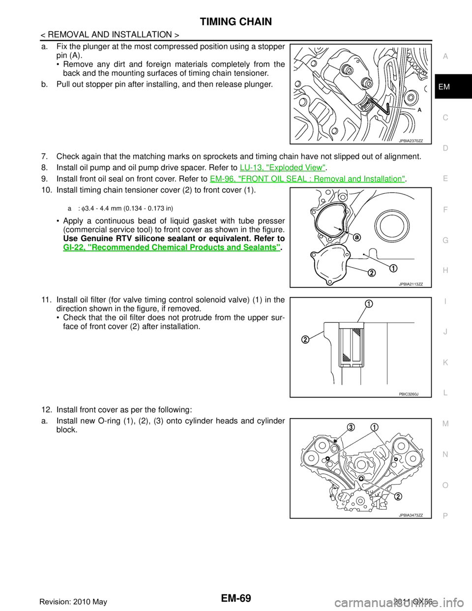
a. Fix the plunger at the most compressed position using a stopper
pin (A).
Remove any dirt and foreign materials completely from theback and the mounting surfaces of timing chain tensioner.
b. Pull out stopper pin after installing, and then release plunger.
7. Check again that the matching marks on sprockets and timing chain have not slipped out of alignment.
8. Install oil pump and oil pump drive spacer. Refer to LU-13, "
Exploded View".
9. Install front oil seal on front cover. Refer to EM-96, "
FRONT OIL SEAL : Removal and Installation".
10. Install timing chain tensioner cover (2) to front cover (1).
Apply a continuous bead of liquid gasket with tube presser(commercial service tool) to front cover as shown in the figure.
Use Genuine RTV silicone seal ant or equivalent. Refer to
GI-22, "
Recommended Chemical Products and Sealants".
11. Install oil filter (for valve timing control solenoid valve) (1) in the direction shown in the figure, if removed.
Check that the oil filter does not protrude from the upper sur-
face of front cover (2) after installation.
12. Install front cover as per the following:
a. Install new O-ring (1), (2), (3) onto cylinder heads and cylinder block.
JPBIA2370ZZ
a: φ3.4 - 4.4 mm (0.134 - 0.173 in)
JPBIA2113ZZ
PBIC3260J
JPBIA3473ZZ
Revision: 2010 May2011 QX56
Page 2632 of 5598
EM-70
< REMOVAL AND INSTALLATION >
TIMING CHAIN
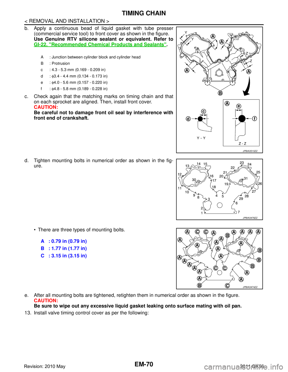
b. Apply a continuous bead of liquid gasket with tube presser(commercial service tool) to front cover as shown in the figure.
Use Genuine RTV silicone seal ant or equivalent. Refer to
GI-22, "
Recommended Chemical Products and Sealants".
c. Check again that the matching marks on timing chain and that on each sprocket are aligned. Then, install front cover.
CAUTION:
Be careful not to damage front oil seal by interference with
front end of crankshaft.
d. Tighten mounting bolts in numerical order as shown in the fig- ure.
There are three types of mounting bolts.
e. After all mounting bolts are tightened, retighten t hem in numerical order as shown in the figure.
CAUTION:
Be sure to wipe out any excessive liquid gasket leaking onto surface mating with oil pan.
13. Install valve timing control cover as per the following:
A : Junction between cylinder block and cylinder head
B : Protrusion
c : 4.3 - 5.3 mm (0.169 - 0.209 in)
d: φ3.4 - 4.4 mm (0.134 - 0.173 in)
e: φ4.0 - 5.6 mm (0.157 - 0.220 in)
f: φ4.8 - 5.8 mm (0.189 - 0.228 in)
JPBIA3510ZZ
JPBIA3478ZZ
A : 0.79 in (0.79 in)
B : 1.77 in (1.77 in)
C : 3.15 in (3.15 in)
JPBIA3474ZZ
Revision: 2010 May2011 QX56
Page 2672 of 5598
EM-110
< UNIT DISASSEMBLY AND ASSEMBLY >
CYLINDER BLOCK
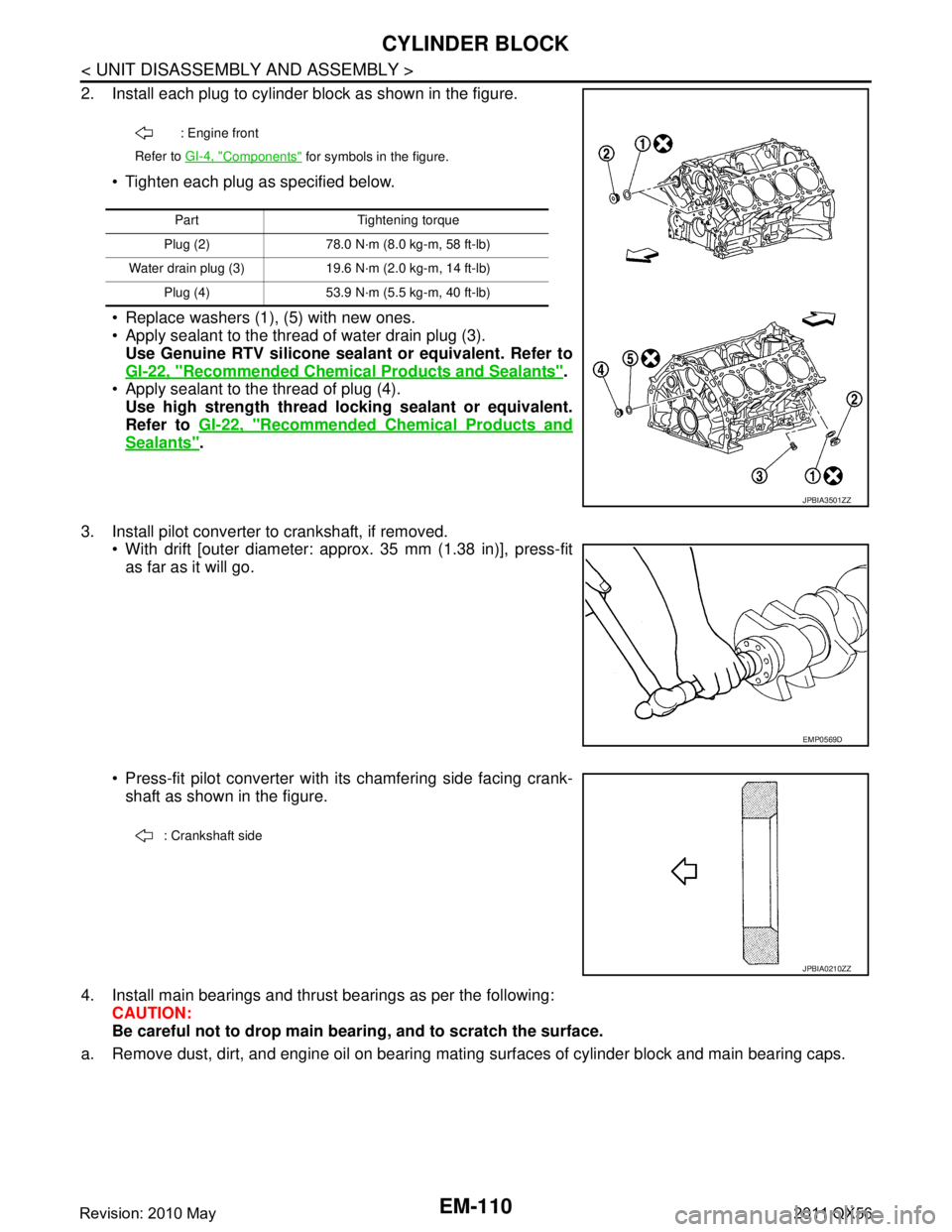
2. Install each plug to cylinder block as shown in the figure. Tighten each plug as specified below.
Replace washers (1), (5) with new ones.
Apply sealant to the thread of water drain plug (3).Use Genuine RTV silicone seal ant or equivalent. Refer to
GI-22, "
Recommended Chemical Pr oducts and Sealants".
Apply sealant to the thread of plug (4). Use high strength thread lo cking sealant or equivalent.
Refer to GI-22, "
Recommended Chemical Products and
Sealants".
3. Install pilot converter to crankshaft, if removed. With drift [outer diameter: appr ox. 35 mm (1.38 in)], press-fit
as far as it will go.
Press-fit pilot converter with its chamfering side facing crank- shaft as shown in the figure.
4. Install main bearings and thrust bearings as per the following: CAUTION:
Be careful not to drop main b earing, and to scratch the surface.
a. Remove dust, dirt, and engine oil on bearing mating surfaces of cylinder block and main bearing caps.
: Engine front
Refer to GI-4, "
Components" for symbols in the figure.
Part Tightening torque
Plug (2) 78.0 N·m (8.0 kg-m, 58 ft-lb)
Water drain plug (3) 19.6 N·m (2.0 kg-m, 14 ft-lb) Plug (4) 53.9 N·m (5.5 kg-m, 40 ft-lb)
JPBIA3501ZZ
EMP0569D
: Crankshaft side
JPBIA0210ZZ
Revision: 2010 May2011 QX56
Page 2674 of 5598
![INFINITI QX56 2011 Factory User Guide
EM-112
< UNIT DISASSEMBLY AND ASSEMBLY >
CYLINDER BLOCK
e. Tighten main bearing cap bolts (M12) in order of No. 1 - 10(clockwise).
CAUTION:
Use the angle wrench [SST: KV10112100 (BT8653-A)] (A) to
ch](/img/42/57033/w960_57033-2673.png "INFINITI QX56 2011 Factory User Guide
EM-112
< UNIT DISASSEMBLY AND ASSEMBLY >
CYLINDER BLOCK
e. Tighten main bearing cap bolts (M12) in order of No. 1 - 10(clockwise).
CAUTION:
Use the angle wrench [SST: KV10112100 (BT8653-A)] (A) to
ch")
EM-112
< UNIT DISASSEMBLY AND ASSEMBLY >
CYLINDER BLOCK
e. Tighten main bearing cap bolts (M12) in order of No. 1 - 10(clockwise).
CAUTION:
Use the angle wrench [SST: KV10112100 (BT8653-A)] (A) to
check tightening angl e. Never make judgment by visual
inspection.
f. Tighten main bearing cap sub bolts (M9) in order of No. 11 - 20. (clockwise)
g. Tighten side bolts (M10) in order of No. 21 - 30. After installing bolts, check that crankshaft can be rotated smoothly by hand.
Check the crankshaft end play. Refer to EM-137, "
CylinderBlock".
8. Install rear oil seal retainer. Apply a continuous bead of liquid gasket with tube presser
(commercial service tool) to rear oil seal retainer as shown in
the figure.
Use Genuine RTV silicone seal ant or equivalent. Refer to
GI-22, "
Recommended Chemical Products and Sealants".
9. Install rear oil seal on rear oil seal retainer.
Apply new engine oil to both oil seal lip (A) and dust seal lip(B).
Install it so that each seal lip is oriented as shown in the figure. CAUTION:
Be careful not to scratch or make burrs on circumference
of oil seal.
Press in rear oil seal (1) to the position as shown in the figure.
Using a suitable drift [outer diameter: 101 mm (3.98 in)].
Check the garter spring is in position and seal lips are not inverted.
10. Install piston to connecting rod as per the following: Angle tightening: 40 degrees
Angle tightening: 30 degrees
JPBIA2149ZZ
: 49.0 N·m (5.0 kg-m, 36 ft-lb)
A : Protrusion
b : 4.0 - 5.6 mm (0.157 - 0.220 in)
c:
φ3.4 - 4.4 mm (0.134 - 0.173 in)
JPBIA2102ZZ
: Engine inside
: Engine outside
JPBIA0054ZZ
B : Rear oil seal retainer rear end face
a : 0 - 0.5 mm (0 - 0.020 in)
JPBIA0152ZZ
Revision: 2010 May2011 QX56
Page 2965 of 5598

GI-1
GENERAL INFORMATION
C
DE
F
G H
I
J
K L
M B
GI
SECTION GI
N
O P
CONTENTS
GENERAL INFORMATION
HOW TO USE THIS MANU AL ......................3
HOW TO USE THIS MANUAL ....................... .....3
Description .......................................................... ......3
Terms ........................................................................3
Units ..........................................................................3
Contents ....................................................................3
Relation between Illustrations and Descriptions .......4
Components ..............................................................4
HOW TO FOLLOW TROUBLE DIAGNOSES .....6
Description ................................................................6
How to Follow Test Groups in Trouble Diagnosis ......6
Key to Symbols Signifying Measurements or Pro-
cedures ............................................................... ......
7
HOW TO READ WIRING DIAGRAMS ................9
Connector Symbols ............................................. ......9
Sample/Wiring Diagram -Example- .........................10
Connector Information .............................................12
ABBREVIATIONS .......................................... ....14
Abbreviation List .................................................. ....14
TIGHTENING TORQUE OF STANDARD
BOLTS ................................................................
19
Description .......................................................... ....19
Tightening Torque Table (New Standard Includ-
ed) ...........................................................................
19
RECOMMENDED CHEMICAL PRODUCTS
AND SEALANTS ................................................
22
Recommended Chemical Products and Sealants ....22
VEHICLE INFORMATION ............................23
IDENTIFICATION INFORMATION ................. ....23
Model Variation ................................................... ....23
Information About Identification or Model Code ......23
Dimensions .............................................................25
Wheels & Tires ........................................................25
PRECAUTION ..............................................26
PRECAUTIONS .................................................26
Description ........................................................... ....26
Precaution for Supplemental Restraint System
(SRS) "AIR BAG" and "SEAT BELT PRE-TEN-
SIONER" .................................................................
26
Precautions For Xenon Headlamp Service .............26
Precaution Necessary for Steering Wheel Rota-
tion after Battery Disconnect ...................................
27
Precaution for Procedure without Cowl Top Cover ....27
General Precautions ................................................27
Three Way Catalyst .................................................29
Multiport Fuel Injection System or Engine Control
System .....................................................................
29
Hoses ......................................................................29
Engine Oils ..............................................................30
Air Conditioning .......................................................31
Fuel ..........................................................................31
LIFTING POINT .................................................32
Pantograph Jack ......................................................32
Garage Jack and Safety Stand ................................32
2-Pole Lift ................................................................33
TOW TRUCK TOWING .....................................34
Tow Truck Towing ...................................................34
Vehicle Recovery (Freeing a Stuck Vehicle) ...........34
BASIC INSPECTION ...................................36
SERVICE INFORMATION FOR ELECTRICAL
INCIDENT ..........................................................
36
Work Flow ............................................................ ....36
Control Units and Electrical Parts ............................36
How to Check Terminal ...........................................37
Intermittent Incident .................................................40
Circuit Inspection .....................................................43
CONSULT-III/GST CHECKING SYSTEM .........48
Description ...............................................................48
CONSULT-III Function and System Application*1 ....48
Revision: 2010 May2011 QX56
Page 2992 of 5598
GI-28
< PRECAUTION >
PRECAUTIONS
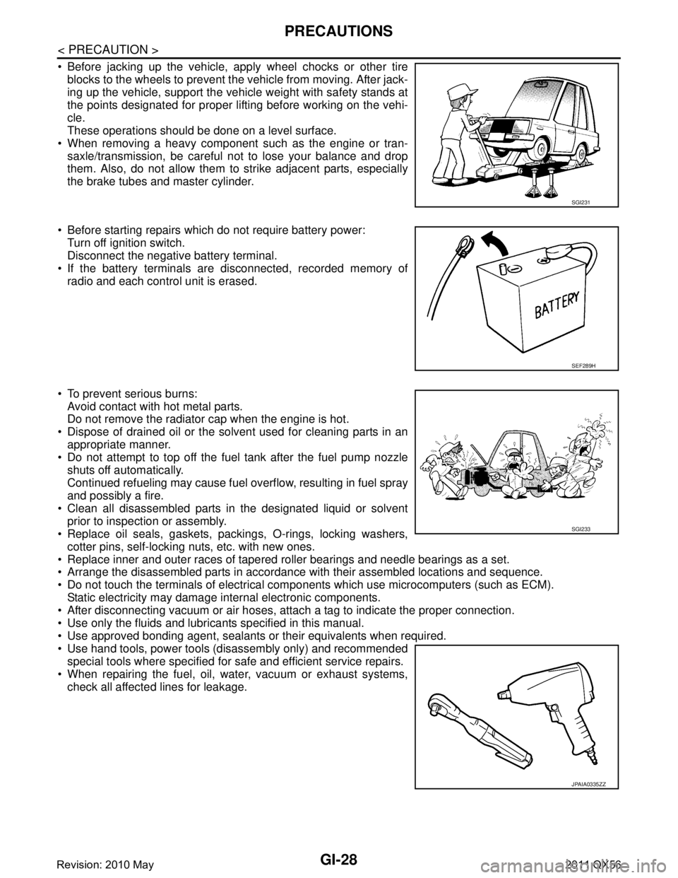
Before jacking up the vehicle, apply wheel chocks or other tireblocks to the wheels to prevent t he vehicle from moving. After jack-
ing up the vehicle, support the vehicle weight with safety stands at
the points designated for proper lifting before working on the vehi-
cle.
These operations should be done on a level surface.
When removing a heavy component such as the engine or tran- saxle/transmission, be careful not to lose your balance and drop
them. Also, do not allow them to strike adjacent parts, especially
the brake tubes and master cylinder.
Before starting repairs which do not require battery power: Turn off ignition switch.
Disconnect the negative battery terminal.
If the battery terminals are disconnected, recorded memory of
radio and each control unit is erased.
To prevent serious burns: Avoid contact with hot metal parts.
Do not remove the radiator cap when the engine is hot.
Dispose of drained oil or the solvent used for cleaning parts in an appropriate manner.
Do not attempt to top off the fuel tank after the fuel pump nozzle
shuts off automatically.
Continued refueling may cause fuel overflow, resulting in fuel spray
and possibly a fire.
Clean all disassembled parts in the designated liquid or solvent prior to inspection or assembly.
Replace oil seals, gaskets, packings, O-rings, locking washers,
cotter pins, self-locking nuts, etc. with new ones.
Replace inner and outer races of tapered roller bearings and needle bearings as a set.
Arrange the disassembled parts in accordance with their assembled locations and sequence.
Do not touch the terminals of electrical com ponents which use microcomputers (such as ECM).
Static electricity may damage internal electronic components.
After disconnecting vacuum or air hoses, atta ch a tag to indicate the proper connection.
Use only the fluids and lubricants specified in this manual.
Use approved bonding agent, sealants or their equivalents when required.
Use hand tools, power tools (disassembly only) and recommended special tools where specified for safe and efficient service repairs.
When repairing the fuel, oil, water, vacuum or exhaust systems, check all affected lines for leakage.
SGI231
SEF289H
SGI233
JPAIA0335ZZ
Revision: 2010 May2011 QX56