washer fluid INFINITI QX56 2011 Factory User Guide
[x] Cancel search | Manufacturer: INFINITI, Model Year: 2011, Model line: QX56, Model: INFINITI QX56 2011Pages: 5598, PDF Size: 94.53 MB
Page 3754 of 5598
MWI
SYSTEMMWI-11
< SYSTEM DESCRIPTION >
C
DE
F
G H
I
J
K L
M B A
O P
ARRANGEMENT OF COMBINATION METER
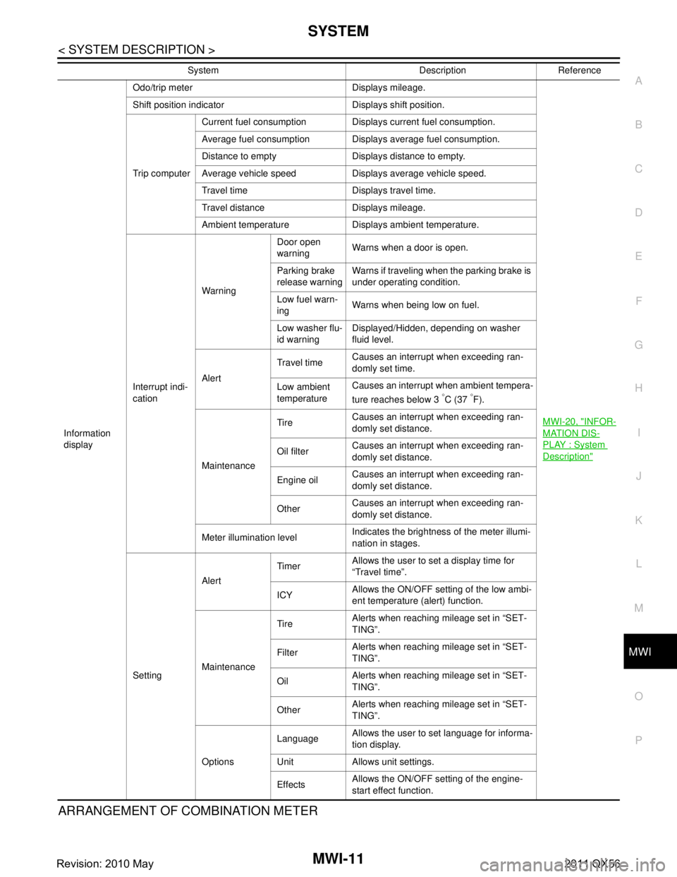
Information
display Odo/trip meter Displays mileage.
MWI-20, "
INFOR-
MATION DIS-
PLAY : System
Description"
Shift position indicator Displays shift position.
Trip computerCurrent fuel consumption Displays current fuel consumption.
Average fuel consumption Displays average fuel consumption.
Distance to empty Displays distance to empty.
Average vehicle speed Displays average vehicle speed.
Travel time Displays travel time.
Travel distance Displays mileage.
Ambient temperature Displays ambient temperature.
Interrupt indi-
cation Warning
Door open
warning
Warns when a door is open.
Parking brake
release warning Warns if traveling when the parking brake is
under operating condition.
Low fuel warn-
ing Warns when being low on fuel.
Low washer flu-
id warning Displayed/Hidden, depending on washer
fluid level.
Alert Travel time
Causes an interrupt when exceeding ran-
domly set time.
Low ambient
temperature Causes an interrupt when ambient tempera-
ture reaches below 3
°C (37 °F).
Maintenance Tire
Causes an interrupt when exceeding ran-
domly set distance.
Oil filter Causes an interrupt when exceeding ran-
domly set distance.
Engine oil Causes an interrupt when exceeding ran-
domly set distance.
Other Causes an interrupt when exceeding ran-
domly set distance.
Meter illumination level Indicates the brightness of the meter illumi-
nation in stages.
Setting Alert
Timer
Allows the user to set a display time for
“Travel time”.
ICY Allows the ON/OFF setting of the low ambi-
ent temperature (alert) function.
Maintenance Tire
Alerts when reaching mileage set in “SET-
TING”.
Filter Alerts when reaching mileage set in “SET-
TING”.
Oil Alerts when reaching mileage set in “SET-
TING”.
Other Alerts when reaching mileage set in “SET-
TING”.
Options Language
Allows the user to set language for informa-
tion display.
Unit Allows unit settings.
Effects Allows the ON/OFF setting of the engine-
start effect function.
System Description Reference
Revision: 2010 May2011 QX56
Page 3759 of 5598
MWI-16
< SYSTEM DESCRIPTION >
SYSTEM
OIL PRESSURE WARNING LAMP : System Description
INFOID:0000000006221709
IPDM E/R reads the ON/OFF signals fr om the oil pressure switch and transmits the oil pressure switch sig-
nal to the combination meter via BCM with the CAN communication.
The combination meter turns the oil pressure warning lamp ON (at the time of a reduction in hydraulic pres-
sure)/OFF (except at the time of a reduction in hydraulic pressure) according to the oil pressure switch signal
received via CAN communication.
MASTER WARNING LAMP
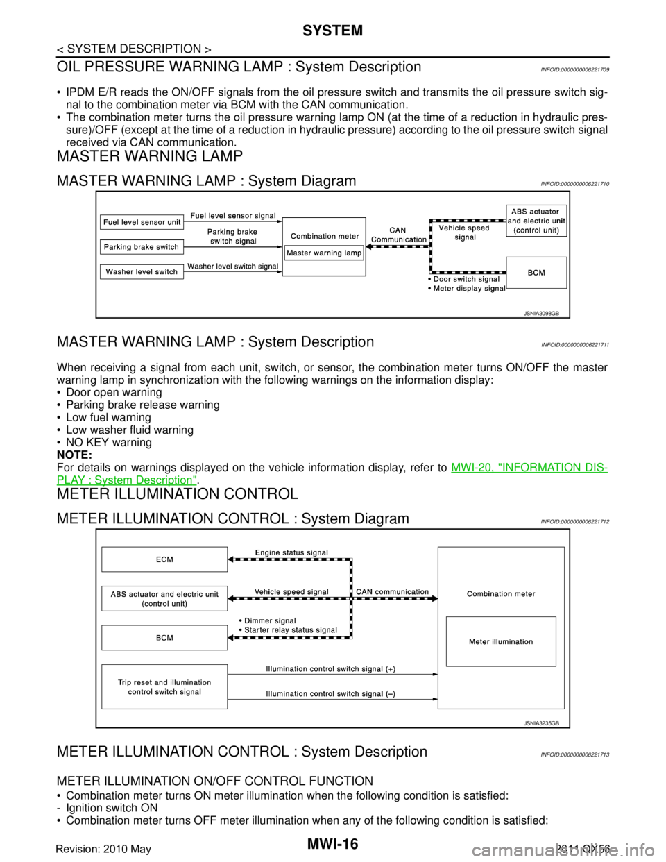
MASTER WARNING LAMP : System DiagramINFOID:0000000006221710
MASTER WARNING LAMP : System DescriptionINFOID:0000000006221711
When receiving a signal from each unit, switch, or s ensor, the combination meter turns ON/OFF the master
warning lamp in synchronization with the following warnings on the information display:
Door open warning
Parking brake release warning
Low fuel warning
Low washer fluid warning
NO KEY warning
NOTE:
For details on warnings displayed on the vehicle information display, refer to MWI-20, "
INFORMATION DIS-
PLAY : System Description".
METER ILLUMINATION CONTROL
METER ILLUMINATION CONTROL : System DiagramINFOID:0000000006221712
METER ILLUMINATION CONTRO L : System DescriptionINFOID:0000000006221713
METER ILLUMINATION ON/OFF CONTROL FUNCTION
Combination meter turns ON meter illumination when the following condition is satisfied:
- Ignition switch ON
Combination meter turns OFF meter illumination when any of the following condition is satisfied:
JSNIA3098GB
JSNIA3235GB
Revision: 2010 May2011 QX56
Page 3767 of 5598
MWI-24
< SYSTEM DESCRIPTION >
SYSTEM
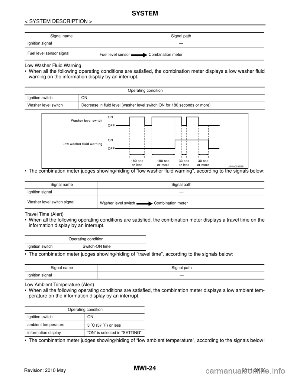
Low Washer Fluid Warning
When all the following operating conditions are satisfied, the combination meter displays a low washer fluid
warning on the information display by an interrupt.
The combination meter judges showing/hiding of “low washer fluid warning”, according to the signals below:
Travel Time (Alert)
When all the following operating conditions are satisfied, the combination meter displays a travel time on the
information display by an interrupt.
The combination meter judges showing/hiding of “travel time”, according to the signals below:
Low Ambient Temperature (Alert)
When all the following operating conditions are satisfied, the combination meter displays a low ambient tem-
perature on the information display by an interrupt.
The combination meter judges showing/hiding of “low ambient temperature”, according to the signals below:
Signal name Signal path
Ignition signal —
Fuel level sensor signal Fuel level sensor Combination meter
Operating condition
Ignition switch ON
Washer level switch Decrease in fluid level (washer level switch ON for 180 seconds or more)
JSNIA0033GB
Signal name Signal path
Ignition signal —
Washer level switch signal Washer level switch Combination meter
Operating condition
Ignition switch Switch-ON time
Signal name Signal path
Ignition signal —
Operating condition
Ignition switch ON
ambient temperature 3
°C (37 °F) or less
information display “ON” is selected in “SETTING”
Revision: 2010 May2011 QX56
Page 3774 of 5598
![INFINITI QX56 2011 Factory User Guide
MWI
DIAGNOSIS SYSTEM (COMBINATION METER)
MWI-31
< SYSTEM DESCRIPTION >
C
D E
F
G H
I
J
K L
M B A
O P
W TEMP METER
[ ° C] XValue of engine coolant temperature signal is received from ECM via CAN com INFINITI QX56 2011 Factory User Guide
MWI
DIAGNOSIS SYSTEM (COMBINATION METER)
MWI-31
< SYSTEM DESCRIPTION >
C
D E
F
G H
I
J
K L
M B A
O P
W TEMP METER
[ ° C] XValue of engine coolant temperature signal is received from ECM via CAN com](/img/42/57033/w960_57033-3773.png)
MWI
DIAGNOSIS SYSTEM (COMBINATION METER)
MWI-31
< SYSTEM DESCRIPTION >
C
D E
F
G H
I
J
K L
M B A
O P
W TEMP METER
[ ° C] XValue of engine coolant temperature signal is received from ECM via CAN com-
munication.
NOTE:
215 is displayed when the malfunction signal is input.
ABS W/L
[On/Off] Status of ABS warning lamp detected fr
om ABS warning lamp signal is received
from ABS actuator and electric unit (control unit) via CAN communication.
VDC/TCS IND
[On/Off] Status of VDC OFF indicator lamp detected from VDC OFF indicator lamp signal
is received from ABS actuator
and electric unit (control unit) via CAN communica-
tion.
SLIP IND
[On/Off] Status of VDC warning lamp detected from VDC warning lamp signal received
from ABS actuator and electric unit (control unit) via CAN communication.
BRAKE W/L
[On/Off] Status of brake warning lamp detected from brake warning lamp signal is received
from ABS actuator and electric unit (control unit) via CAN communication.
NOTE:
Displays “Off” if the brake warning lamp is illuminated when the valve check starts,
the parking brake switch is turned ON or the brake fluid level switch is turned ON.
DOOR W/L
[On/Off] Status of door open warning detected from door switch signal received from BCM
via CAN communication.
HI-BEAM IND
[On/Off] Status of high beam indicator lamp detected from high beam request signal is re-
ceived from BCM via CAN communication.
TURN IND
[On/Off] Status of turn indicator lamp detected from turn indicator signal is received from
BCM via CAN communication.
FR FOG IND
[Off] This item is displayed, but cannot be monitored.
RR FOG IND
[Off] This item is displayed, but cannot be monitored.
LIGHT IND
[On/Off] Status of light indicator lamp detected from position light request signal is received
from BCM via CAN communication.
OIL W/L
[On/Off] Status of oil pressure warning lamp detected from oil pressure switch signal is re-
ceived from BCM via CAN communication.
MIL
[On/Off] Status of malfunction indicator lamp detected from malfunctioning indicator lamp
signal is received from ECM via CAN communication.
GLOW IND
[Off] This item is displayed, but cannot be monitored.
CRUISE IND
[On/Off] Status of CRUISE indicator detected from ASCD status signal is received from
ECM via CAN communicat ion. (ASCD models)
Status of CRUISE indicator de tected from meter display signal is received from
ADAS control unit via CAN communication. (ICC models)
SET IND
[On/Off] Status of SET indicator detected from meter display signal is received from ADAS
control unit via CAN communication.
CRUISE W/L
[On/Off] Status of CRUISE warning lamp
judged from ICC warning lamp signal received
from ADAS control unit with CAN communication line.
BA W/L
[On/Off] Status of IBA OFF indicator lamp judged from IBA OFF indicator lamp signal re-
ceived from ADAS control unit with CAN communication line.
ATC/T-AMT W/L
[On/Off] Status of A/T CHECK warning lamp judged
from A/T CHECK indicator lamp signal
received from TCM with CAN communication line.
ATF TEMP W/L
[Off] This item is displayed, but cannot be monitored.
4WD W/L
[On/Off] Status of 4WD warning lamp judged from 4WD warning lamp signal received from
4WD control unit with
CAN communication line.
FUEL W/L
[On/Off] Low-fuel warning lamp status detected by the identified fuel level.
WASHER W/L
[On/Off] Status of low washer fluid warning judged from washer level switch input to com-
bination meter.
Display item [Unit]
MAIN
SIGNALS Description
Revision: 2010 May2011 QX56
Page 3777 of 5598

MWI-34
< SYSTEM DESCRIPTION >
DIAGNOSIS SYSTEM (COMBINATION METER)
Display item Description
ABS W/L Lighting history of ABS warning lamp.
VDC/TCS IND Lighting history of VDC OFF indicator lamp.
SLIP IND Lighting history of VDC warning lamp.
BRAKE W/L Lighting history of brake warning lamp.
DOOR W/L Lighting history of door open warning.
TRUNK/GLAS-H This item is displa yed, but cannot be monitored.
OIL W/L Lighting history of oil pressure warning lamp.
C-ENG W/L Lighting history of malfunction indicator lamp.
C-ENG2 W/L This item is displayed, but cannot be monitored.
CRUISE IND Lighting history of CRUISE indicator lamp.
SET IND Lighting history of SET indicator lamp.
CRUISE W/L Lighting history of CRUISE warning lamp.
BA W/L Lighting history of IBA OFF indicator lamp.
O/D OFF IND This item is displayed, but cannot be monitored.
ATC/T-AMT W/L Lighting history of A/T CHECK warning lamp.
ATF TEMP W/L This item is displayed, but cannot be monitored.
CVT IND This item is displayed, but cannot be monitored.
SPORT IND This item is displayed, but cannot be monitored.
4WD W/L Lighting history of 4WD warning lamp.
FUEL W/L Lighting history of low fuel level warning.
WASHER W/L Lighting history of low washer fluid warning.
AIR PRES W/L Lighting history of low tire pressure warning lamp.
KEY G/Y W/L Lighting history of KEY warning lamp.
KEY R W/L This item is displaye d, but cannot be monitored.
KEY KNOB W/L This item is displa yed, but cannot be monitored.
EPS W/L This item is displayed, but cannot be monitored.
e-4WD This item is displayed, but cannot be monitored.
AFS OFF IND This item is displayed, but cannot be monitored.
4WAS/RAS W/L This item is displayed, but cannot be monitored.
HDC W/L This item is displayed, but cannot be monitored.
SYS FAIL W/L This item is displa yed, but cannot be monitored.
SFT POSI W/L This item is displayed, but cannot be monitored.
HV BAT W/L This item is displayed, but cannot be monitored.
HEV BRAKE W/L This item is displayed, but cannot be monitored.
SFT OPER W/L This item is displayed, but cannot be monitored.
LANE W/L Lighting history of lane departure warning lamp.
CHAGE W/L This item is displayed, but cannot be monitored.
OIL LEV LOW This item is displayed, but cannot be monitored.
DPF W/L This item is displayed, but cannot be monitored.
TRAILER IND This item is displayed, but cannot be monitored.
RUN FLAT W/L This item is displa yed, but cannot be monitored.
E-SUS W/L This item is displayed, but cannot be monitored.
LAUNCH CNT W/L This item is displayed, but cannot be monitored.
BRAKE PAD W/L This item is displa yed, but cannot be monitored.
Revision: 2010 May2011 QX56
Page 3824 of 5598
MWI
THE LOW WASHER FLUID WARNING CONTINUES DISPLAYING, OR DOES
NOT DISPLAY
MWI-81
< SYMPTOM DIAGNOSIS >
C
DE
F
G H
I
J
K L
M B A
O P
THE LOW WASHER FLUID WARNING CONTINUES DISPLAYING, OR
DOES NOT DISPLAY
DescriptionINFOID:0000000006221769
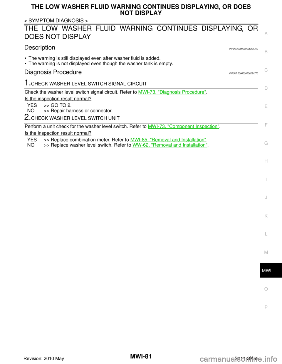
The warning is still displayed even after washer fluid is added.
The warning is not displayed even though the washer tank is empty.
Diagnosis ProcedureINFOID:0000000006221770
1.CHECK WASHER LEVEL SWITCH SIGNAL CIRCUIT
Check the washer level switch signal circuit. Refer to MWI-73, "
Diagnosis Procedure".
Is the inspection result normal?
YES >> GO TO 2.
NO >> Repair harness or connector.
2.CHECK WASHER LEVEL SWITCH UNIT
Perform a unit check for the washer level switch. Refer to MWI-73, "
Component Inspection".
Is the inspection result normal?
YES >> Replace combination meter. Refer to MWI-85, "Removal and Installation".
NO >> Replace washer level switch. Refer to WW-62, "
Removal and Installation".
Revision: 2010 May2011 QX56
Page 4266 of 5598
REAR SHOCK ABSORBERRSU-11
< REMOVAL AND INSTALLATION >
C
DF
G H
I
J
K L
M A
B
RSU
N
O P
Inadvertent piping removal causes fluid to splatter.
2. Remove tires with power tool. Refer to WT-64, "
Removal and Installation".
3. Remove height sensor from rear lower link (right side). Refer to EXL-136, "
Removal and Installation".
4. Remove vehicle height sensor from rear lower link (left side). Refer to SCS-98, "
Removal and Installa-
tion".
5. Remove air tube from shock absorber assembly. Refer to SCS-95, "
Removal and Installation".
6. Remove middle tube assembly from shock absorber assembly. (With HBMC) Refer to SCS-44, "
REAR
TUBE ASSEMBLY : Removal and Installation".
7. Remove shock absorber mounting bolt (lower side).
8. Remove piston rod lock nut.
9. Remove bracket, bushings, and shock absorber. (With HBMC)
10. Remove washers, bushings, and shock absorber. (Without HBMC)
11. Perform inspection after removal. Refer to RSU-11, "
Inspection and Adjustment".
INSTALLATION
Note the following, and install in the reverse order of removal.
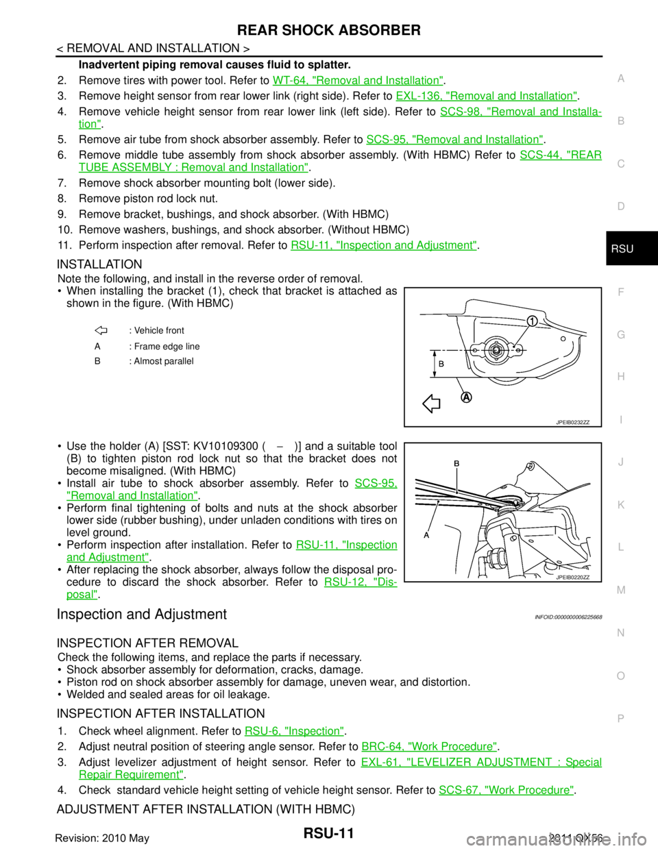
When installing the bracket (1), check that bracket is attached as
shown in the figure. (With HBMC)
Use the holder (A) [SST: KV10109300 ( −)] and a suitable tool
(B) to tighten piston rod lock nut so that the bracket does not
become misaligned. (With HBMC)
Install air tube to shock absorber assembly. Refer to SCS-95,
"Removal and Installation".
Perform final tightening of bolts and nuts at the shock absorber
lower side (rubber bushing), under unladen conditions with tires on
level ground.
Perform inspection after installation. Refer to RSU-11, "
Inspection
and Adjustment".
After replacing the shock absorber, always follow the disposal pro- cedure to discard the shock absorber. Refer to RSU-12, "
Dis-
posal".
Inspection and AdjustmentINFOID:0000000006225668
INSPECTION AFTER REMOVAL
Check the following items, and replace the parts if necessary.
Shock absorber assembly for deformation, cracks, damage.
Piston rod on shock absorber assembly for damage, uneven wear, and distortion.
Welded and sealed areas for oil leakage.
INSPECTION AFTER INSTALLATION
1. Check wheel alignment. Refer to RSU-6, "Inspection".
2. Adjust neutral position of steering angle sensor. Refer to BRC-64, "
Work Procedure".
3. Adjust levelizer adjustment of height sensor. Refer to EXL-61, "
LEVELIZER ADJUSTMENT : Special
Repair Requirement".
4. Check standard vehicle height setting of vehicle height sensor. Refer to SCS-67, "
Work Procedure".
ADJUSTMENT AFTER INSTALLATION (WITH HBMC)
: Vehicle front
A : Frame edge line
B: Almost parallel
JPEIB0232ZZ
JPEIB0220ZZ
Revision: 2010 May2011 QX56
Page 5017 of 5598
ST-30
< PERIODIC MAINTENANCE >
POWER STEERING FLUID
PERIODIC MAINTENANCE
POWER STEERING FLUID
InspectionINFOID:0000000006225597
FLUID LEVEL
1. Check fluid level with engine stopped.
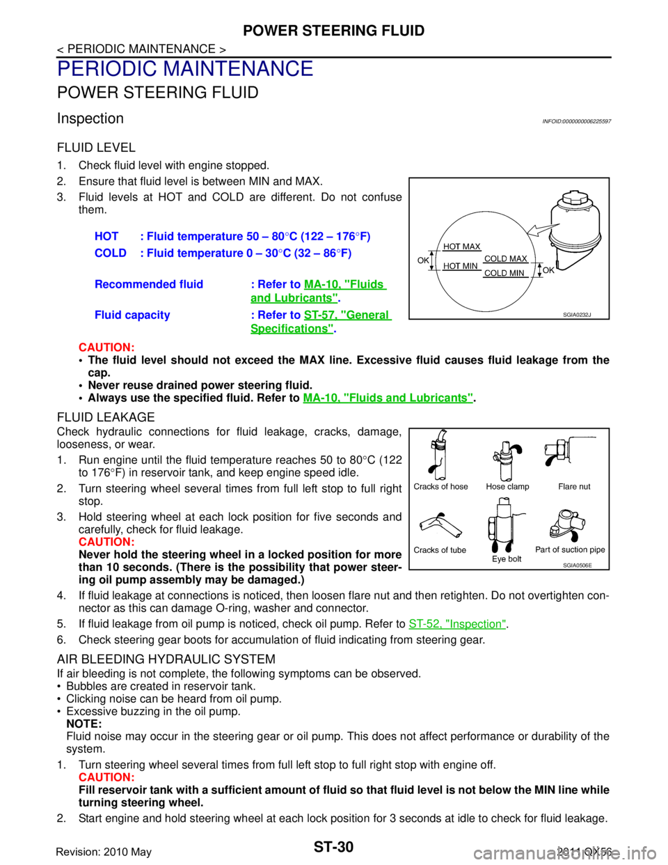
2. Ensure that fluid level is between MIN and MAX.
3. Fluid levels at HOT and COLD are different. Do not confuse
them.
CAUTION:
The fluid level should not exceed the MAX line. Excessive flui d causes fluid leakage from the
cap.
Never reuse drained power steering fluid.
Always use the specified fluid. Refer to MA-10, "
Fluids and Lubricants".
FLUID LEAKAGE
Check hydraulic connections for fluid leakage, cracks, damage,
looseness, or wear.
1. Run engine until the fluid temperature reaches 50 to 80 °C (122
to 176 °F) in reservoir tank, and keep engine speed idle.
2. Turn steering wheel several times from full left stop to full right stop.
3. Hold steering wheel at each lock position for five seconds and carefully, check for fluid leakage.
CAUTION:
Never hold the steering wheel in a locked position for more
than 10 seconds. (There is the possibility that power steer-
ing oil pump assembly may be damaged.)
4. If fluid leakage at connections is noticed, then loos en flare nut and then retighten. Do not overtighten con-
nector as this can damage O-ring, washer and connector.
5. If fluid leakage from oil pump is noticed, check oil pump. Refer to ST-52, "
Inspection".
6. Check steering gear boots for accumulation of fluid indicating from steering gear.
AIR BLEEDING HYDRAULIC SYSTEM
If air bleeding is not complete, the following symptoms can be observed.
Bubbles are created in reservoir tank.
Clicking noise can be heard from oil pump.
Excessive buzzing in the oil pump. NOTE:
Fluid noise may occur in the steering gear or oil pump. This does not affect performance or durability of the
system.
1. Turn steering wheel several times from full left stop to full right stop with engine off. CAUTION:
Fill reservoir tank with a sufficien t amount of fluid so that fluid level is not below the MIN line while
turning steering wheel.
2. Start engine and hold steering wheel at each lock position for 3 seconds at idle to check for fluid leakage.
HOT : Fluid temperature 50 – 80
°C (122 – 176 °F)
COLD : Fluid temperature 0 – 30 °C (32 – 86 °F)
Recommended fluid : Refer to MA-10, "
Fluids
and Lubricants".
Fluid capacity : Refer to ST-57, "
General
Specifications".
SGIA0232J
SGIA0506E
Revision: 2010 May2011 QX56
Page 5036 of 5598
POWER STEERING OIL PUMPST-49
< REMOVAL AND INSTALLATION >
C
DE
F
H I
J
K L
M A
B
ST
N
O P
Removal and InstallationINFOID:0000000006225612
REMOVAL
1. Drain power steering fluid from reservoir tank. CAUTION:
Never reuse drained power steering fluid.
Always use the specified fluid. Refer to MA-10, "
Fluids and Lubricants".
2. Remove the reservoir tank. Refer to CO-13, "
Removal and Installation".
3. Remove the battery and battery tray from vehicle. Refer to PG-164, "
Removal and Installation".
4. Loosen drive belt. Refer to EM-20, "
Removal and Installation".
5. Remove drive belt from oil pump pulley.
6. Remove copper washers and eye bolt (drain fluid from their pipings).
7. Remove suction hose (drain fluid from their pipings).
8. Remove oil pump mounting bolts, and then remove oil pump.
INSTALLATION
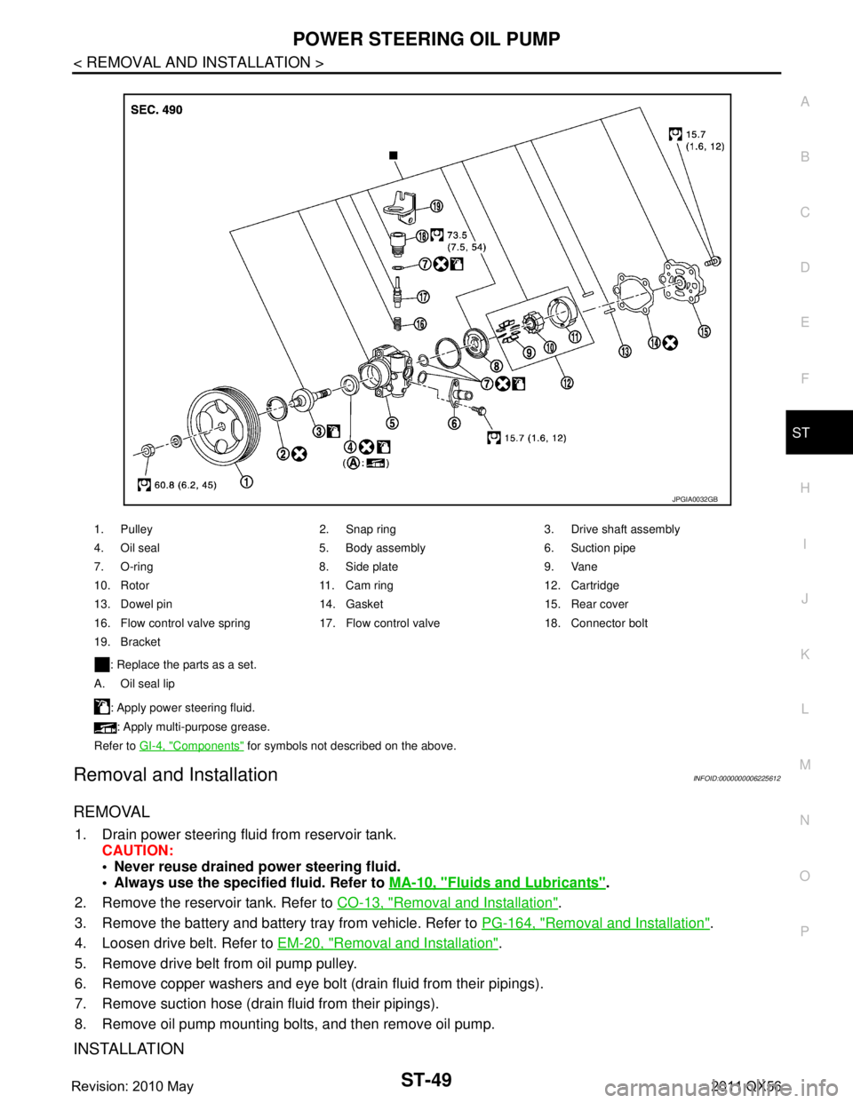
1. Pulley 2. Snap ring 3. Drive shaft assembly
4. Oil seal 5. Body assembly 6. Suction pipe
7. O-ring 8. Side plate 9. Vane
10. Rotor 11. Cam ring 12. Cartridge
13. Dowel pin 14. Gasket 15. Rear cover
16. Flow control valve spring 17. Flow control valve 18. Connector bolt
19. Bracket
: Replace the parts as a set.
A. Oil seal lip
: Apply power steering fluid.: Apply multi-purpose grease.
Refer to GI-4, "
Components" for symbols not described on the above.
JPGIA0032GB
Revision: 2010 May2011 QX56
Page 5037 of 5598
ST-50
< REMOVAL AND INSTALLATION >
POWER STEERING OIL PUMP
Note the following, and install in the reverse order of removal.
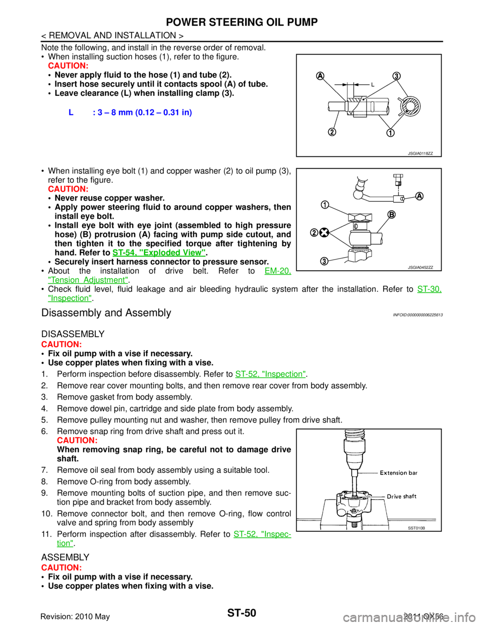
When installing suction hoses (1), refer to the figure.CAUTION:
Never apply fluid to the hose (1) and tube (2).
Insert hose securely until it contacts spool (A) of tube.
Leave clearance (L) when installing clamp (3).
When installing eye bolt (1) and copper washer (2) to oil pump (3), refer to the figure.
CAUTION:
Never reuse copper washer.
Apply power steering fluid to around copper washers, then
install eye bolt.
Install eye bolt with eye join t (assembled to high pressure
hose) (B) protrusion (A) facing with pump side cutout, and
then tighten it to the specifi ed torque after tightening by
hand. Refer to ST-54, "
Exploded View".
Securely insert harness connector to pressure sensor.
About the installation of drive belt. Refer to EM-20,
"TensionAdjustment".
Check fluid level, fluid leakage and air bleeding hydr aulic system after the installation. Refer to ST-30,
"Inspection".
Disassembly and AssemblyINFOID:0000000006225613
DISASSEMBLY
CAUTION:
Fix oil pump with a vise if necessary.
Use copper plates when fixing with a vise.
1. Perform inspection before disassembly. Refer to ST-52, "
Inspection".
2. Remove rear cover mounting bolts, and then remove rear cover from body assembly.
3. Remove gasket from body assembly.
4. Remove dowel pin, cartridge and side plate from body assembly.
5. Remove pulley mounting nut and washer, then remove pulley from drive shaft.
6. Remove snap ring from drive shaft and press out it. CAUTION:
When removing snap ring, be careful not to damage drive
shaft.
7. Remove oil seal from body assembly using a suitable tool.
8. Remove O-ring from body assembly.
9. Remove mounting bolts of suction pipe, and then remove suc- tion pipe and bracket from body assembly.
10. Remove connector bolt, and then remove O-ring, flow control
valve and spring from body assembly
11. Perform inspection after disassembly. Refer to ST-52, "
Inspec-
tion".
ASSEMBLY
CAUTION:
Fix oil pump with a vise if necessary.
Use copper plates when fixing with a vise.L : 3 – 8 mm (0.12 – 0.31 in)
JSGIA0118ZZ
JSGIA0452ZZ
SST010B
Revision: 2010 May2011 QX56