tire pressure INFINITI QX56 2011 Factory Owner's Manual
[x] Cancel search | Manufacturer: INFINITI, Model Year: 2011, Model line: QX56, Model: INFINITI QX56 2011Pages: 5598, PDF Size: 94.53 MB
Page 2941 of 5598

FL-12
< REMOVAL AND INSTALLATION >
EVAP CANISTER
Removal and Installation
INFOID:0000000006414454
REMOVAL
1. Remove the spare tire.
2. Disconnect harness connectors and hoses.
3. Remove EVAP canister fixing bolt.
4. Remove EVAP canister.
NOTE:
The EVAP canister vent control valve and EVAP cont rol system pressure sensor can be removed without
removing the EVAP canister.
INSTALLATION
Install in the reverse order of removal.
NOTE:
Tighten EVAP canister fixing bolt to the specified torque.
Disassembly and AssemblyINFOID:0000000006414455
DISASSEMBLY
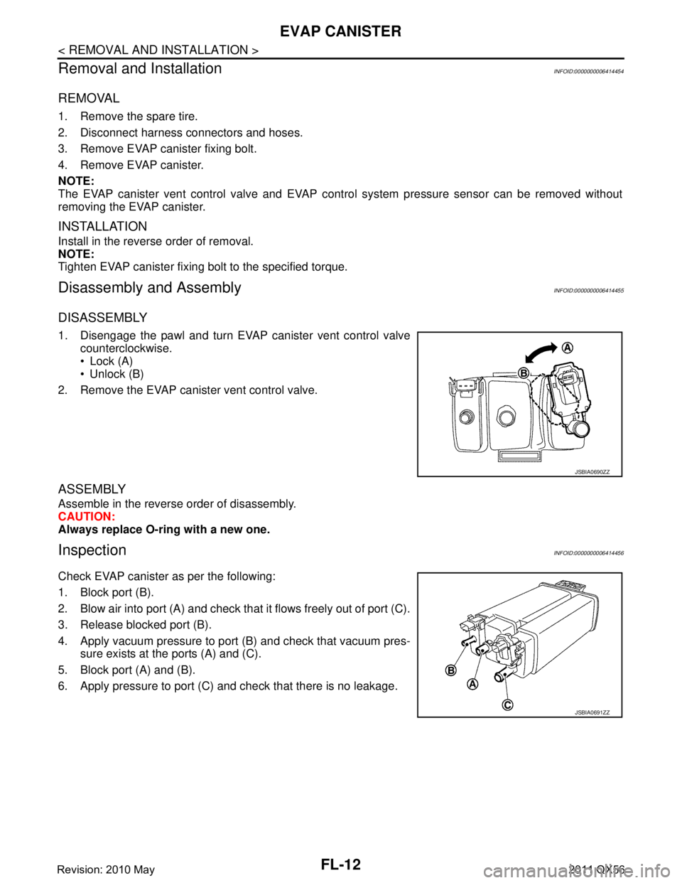
1. Disengage the pawl and turn EVAP canister vent control valve counterclockwise.
Lock (A)
Unlock (B)
2. Remove the EVAP canister vent control valve.
ASSEMBLY
Assemble in the reverse order of disassembly.
CAUTION:
Always replace O-ring with a new one.
InspectionINFOID:0000000006414456
Check EVAP canister as per the following:
1. Block port (B).
2. Blow air into port (A) and check that it flows freely out of port (C).
3. Release blocked port (B).
4. Apply vacuum pressure to port (B) and check that vacuum pres- sure exists at the ports (A) and (C).
5. Block port (A) and (B).
6. Apply pressure to port (C) and check that there is no leakage.
JSBIA0690ZZ
JSBIA0691ZZ
Revision: 2010 May2011 QX56
Page 2949 of 5598

WHEEL ALIGNMENTFSU-7
< PERIODIC MAINTENANCE >
C
DF
G H
I
J
K L
M A
B
FSU
N
O P
WHEEL ALIGNMENT
InspectionINFOID:0000000006225640
DESCRIPTION
Measure wheel alignment under unladen conditions.
NOTE:
“Unladen conditions” means that fuel, engine coolant, and lubricant are full. Spare tire, jack, hand tools and
mats are in designated positions.
PRELIMINARY CHECK
Check the following:
Tires for improper air pressure and wear
Road wheels for runout: Refer to WT-64, "
Inspection".
Wheel bearing axial end play: Refer to FA X - 7 , "
Inspection" (2WD), FAX-16, "Inspection" (4WD).
Lower link and upper link ball joint axial end play: Refer to FSU-15, "
Inspection" and FSU-18, "Inspection".
Shock absorber operation.
Each mounting part of axle and suspension for looseness and deformation
Lower link for cracks, deformation and other damage
Vehicle height (posture)
GENERAL INFORMATION AND RECOMMENDATIONS
A four-wheel thrust alignment should be performed.
- This type of alignment is recomm ended for any NISSAN/INFINITI vehicle.
- The four-wheel “thrust” process helps ensure that t he vehicle is properly aligned and the steering wheel is
centered.
- The alignment rack itself should be capable of accepting any NISSAN/INFINITI vehicle.
- The rack should be checked to ensure that it is level.
Make sure the machine is properly calibrated.
- Your alignment equipment should be regularly ca librated in order to give correct information.
- Check with the manufacturer of your specific equi pment for their recommended Service/Calibration Sched-
ule.
ALIGNMENT PROCESS
IMPORTANT:
Use only the alignment specificati ons listed in this Service Manual.
When displaying the alignment settings, many alignment machines use “indicators”: (Green/red, plus or
minus, Go/No Go). Never use these indicators.
- The alignment specifications programmed into your machine that operate these indicators may not be cor-
rect.
- This may result in an ERROR.
Some newer alignment machines are equipped with an optional “Rolling Compensation” method to “com-
pensate” the sensors (alignment targets or head units). Never use this “Rolling Compensation” method.
- Use the “Jacking Compensation Method”. After installi ng the alignment targets or head units, raise the vehi-
cle and rotate the wheels 1/2 turn both ways.
- See Instructions in the alignment machine you're using for more information on this.
AdjustmentINFOID:0000000006225641
CAMBER, CASTER
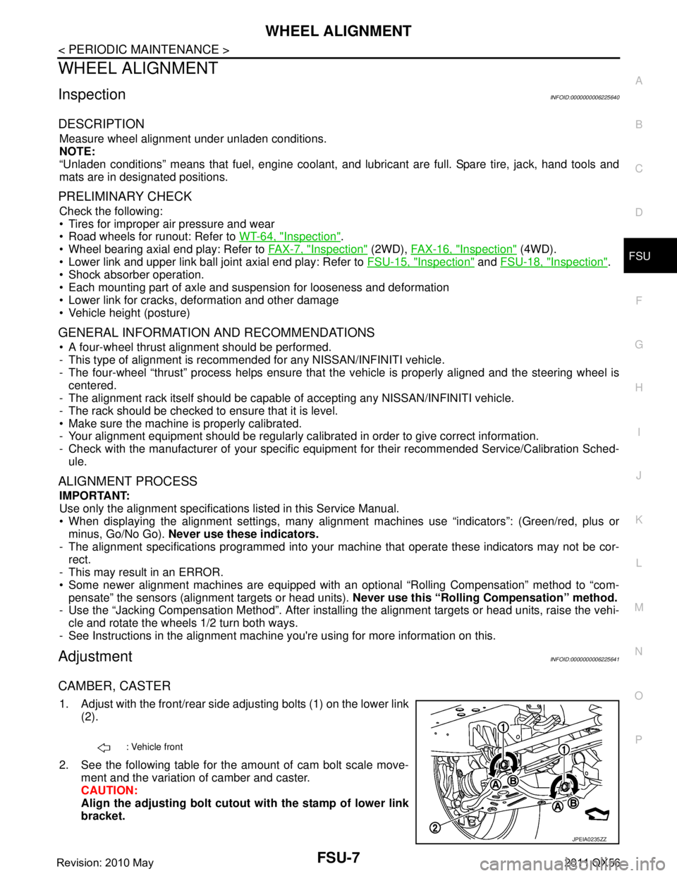
1. Adjust with the front/rear side adjusting bolts (1) on the lower link
(2).
2. See the following table for the amount of cam bolt scale move- ment and the variation of camber and caster.
CAUTION:
Align the adjusting bolt cutout with the stamp of lower link
bracket.
: Vehicle front
JPEIA0235ZZ
Revision: 2010 May2011 QX56
Page 2952 of 5598

FSU-10
< REMOVAL AND INSTALLATION >
FRONT COIL SPRING AND SHOCK ABSORBER
CAUTION:
The shock absorber assembly cannot be disassembled.
Removal and InstallationINFOID:0000000006225643
REMOVAL
1. Reduce system pressure. (With HBMC) Refer to SCS-18, "Work Procedure".
CAUTION:
Inadvertent piping removal causes fluid to splatter.
2. Remove tires with power tool. Refer to WT-64, "
Removal and Installation".
3. Remove brake hose bracket from steering knuckle. Refer to BR-23, "
FRONT : Removal and Installation".
4. Remove caliper assembly mounting bolts. Hang caliper assembly in a place where it will not interfere with work. Refer to BR-37, "
BRAKE CALIPER ASSEMBLY : Removal and Installation".
CAUTION:
Never depress brake pedal while brake caliper is removed.
5. Remove disc rotor. Refer to FA X - 8 , "
Removal and Installation" (2WD), FAX-18, "Removal and Installation"
(4WD).
6. Remove wheel sensor and harness connector. Refer to BRC-134, "
FRONT WHEEL SENSOR : Removal
and Installation".
CAUTION:
Never pull on wheel sensor harness.
7. Remove steering outer socket fr om steering knuckle. Refer to ST-42, "
Removal and Installation".
8. Remove height sensor from upper link (right side). Refer to EXL-136, "
Removal and Installation".
9. Set suitable jack under lower link.
10. Remove stabilizer connecting rod from lower link. (Without HBMC) Refer to FSU-20, "
Removal and Instal-
lation".
11. Separate upper link from steering knuckle. Refer to FSU-17, "
Removal and Installation".
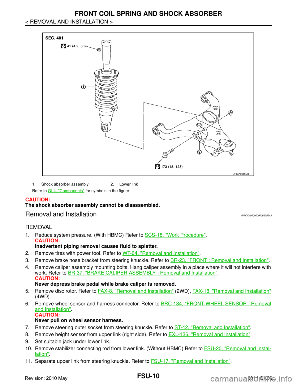
1. Shock absorber assembly 2. Lower link
Refer to GI-4, "
Components" for symbols in the figure.
JPEIA0256GB
Revision: 2010 May2011 QX56
Page 2981 of 5598

ABBREVIATIONSGI-17
< HOW TO USE THIS MANUAL >
C
DE
F
G H
I
J
K L
M B
GI
N
O P
P
R
S
T
V
W
1
ABBREVIATION DESCRIPTION P/S Power steering
PBR Potentio balance resistor
PCV Positive crankcase ventilation
PNP Park/Neutral position PSP Power steering pressurePTC Positive temperature coefficient
PTO Power takeoff
PWM Pulse width modulation
ABBREVIATION DESCRIPTION RAM Random access memoryRAS Rear active steer RH Right-hand
ROM Read only memory RPM Engine speed RR Rear
ABBREVIATION DESCRIPTION SAE Society of Automoti ve Engineers, Inc.
SCK Serial clock
SDS Service Data and Specifications SRT System readiness testSST Special Service Tools
ABBREVIATION DESCRIPTION TC Turbocharger
TCM Transmission control module TCS Traction control system TP Throttle position
TPMS Tire pressure monitoring system TSS Turbine shaft speed
TWC Three way catalytic converter
ABBREVIATION DESCRIPTION VDC Vehicle dynamics control systemVIN Vehicle identification number
VSS Vehicle speed sensor
ABBREVIATION DESCRIPTION WOT Wide open throttle
ABBREVIATION DESCRIPTION 1
11st range first gear
Revision: 2010 May2011 QX56
Page 3443 of 5598
![INFINITI QX56 2011 Factory Owners Manual
LAN
HOW TO USE THIS SECTIONLAN-23
< HOW TO USE THIS MANUAL > [CAN]
C
D
E
F
G H
I
J
K L
B A
O P
N
HOW TO USE THIS MANUAL
HOW TO USE THIS SECTION
CautionINFOID:0000000006220525
This section describes INFINITI QX56 2011 Factory Owners Manual
LAN
HOW TO USE THIS SECTIONLAN-23
< HOW TO USE THIS MANUAL > [CAN]
C
D
E
F
G H
I
J
K L
B A
O P
N
HOW TO USE THIS MANUAL
HOW TO USE THIS SECTION
CautionINFOID:0000000006220525
This section describes](/img/42/57033/w960_57033-3442.png)
LAN
HOW TO USE THIS SECTIONLAN-23
< HOW TO USE THIS MANUAL > [CAN]
C
D
E
F
G H
I
J
K L
B A
O P
N
HOW TO USE THIS MANUAL
HOW TO USE THIS SECTION
CautionINFOID:0000000006220525
This section describes information peculiar to a vehicle and inspection procedures.
For trouble diagnosis procedure, refer to
LAN-18, "
Trouble Diagnosis Procedure".
Abbreviation ListINFOID:0000000006220526
Unit name abbreviations in CONSULT-III CAN diagnosis and in this section are as per the following list.
Abbreviation Unit name
4WD Transfer control unit
A-BAG Air bag diagnosis sensor unit ABS ABS actuator and electric unit (control unit)
ADP Driver seat control unit AFS AFS control unitAPA Accelerator pedal actuator AV AV control unit
BCM BCM
CGW CAN gateway DLC Data link connector
E-SUS Air levelizer control module ECM ECM
HVAC A/C auto amp. ICC ADAS control unit
IPDM-E IPDM E/R LANE Lane camera unit
LASER ICC sensor M&A Combination meter
PSB Pre-crash seat belt control unit (driver side)
PWBD Automatic back door control module
RDR-L Side radar LH
RDR-R Side radar RH STRG Steering angle sensor TCM TCM
TPMS Low tire pressure warning control unit
Revision: 2010 May2011 QX56
Page 3446 of 5598
![INFINITI QX56 2011 Factory Owners Manual
LAN-26
< SYSTEM DESCRIPTION >[CAN]
COMPONENT PARTS
SYSTEM DESCRIPTION
COMPONENT PARTS
Component Parts LocationINFOID:0000000006220530
1. Air bag diagnosis sensor unit 2. Lane camera unit 3. A/T assem INFINITI QX56 2011 Factory Owners Manual
LAN-26
< SYSTEM DESCRIPTION >[CAN]
COMPONENT PARTS
SYSTEM DESCRIPTION
COMPONENT PARTS
Component Parts LocationINFOID:0000000006220530
1. Air bag diagnosis sensor unit 2. Lane camera unit 3. A/T assem](/img/42/57033/w960_57033-3445.png)
LAN-26
< SYSTEM DESCRIPTION >[CAN]
COMPONENT PARTS
SYSTEM DESCRIPTION
COMPONENT PARTS
Component Parts LocationINFOID:0000000006220530
1. Air bag diagnosis sensor unit 2. Lane camera unit 3. A/T assembly
4. AFS control unit 5. Transfer control unit 6. Low tire pressure warning control
unit
7. IPDM E/R 8. CAN gateway 9. ECM
10. A/C auto amp. 11. ICC sensor 12. AV control unit
13. BCM 14. ABS actuator an d electric unit (con-
trol unit) 15. Combination meter
16. Data link connector 17. Steering angle sensor 18. Accelerator pedal actuator
19. Driver seat control un it 20. Pre-crash seat be lt control unit (driv-
er side) 21. Air levelizer control module
22. ADAS control unit 23. Automatic back door control module 24. Side radar LH
25. Side radar RH
JSMIA0343ZZ
Revision: 2010 May2011 QX56
Page 3447 of 5598
![INFINITI QX56 2011 Factory Owners Manual
LAN
SYSTEMLAN-27
< SYSTEM DESCRIPTION > [CAN]
C
D
E
F
G H
I
J
K L
B A
O P
N
SYSTEM
CAN COMMUNICATION SYSTEM
CAN COMMUNICATION SYSTEM : CAN
System Specification ChartINFOID:0000000006220532
Determine INFINITI QX56 2011 Factory Owners Manual
LAN
SYSTEMLAN-27
< SYSTEM DESCRIPTION > [CAN]
C
D
E
F
G H
I
J
K L
B A
O P
N
SYSTEM
CAN COMMUNICATION SYSTEM
CAN COMMUNICATION SYSTEM : CAN
System Specification ChartINFOID:0000000006220532
Determine](/img/42/57033/w960_57033-3446.png)
LAN
SYSTEMLAN-27
< SYSTEM DESCRIPTION > [CAN]
C
D
E
F
G H
I
J
K L
B A
O P
N
SYSTEM
CAN COMMUNICATION SYSTEM
CAN COMMUNICATION SYSTEM : CAN
System Specification ChartINFOID:0000000006220532
Determine CAN system type from the following specification chart.
NOTE:
Refer to LAN-18, "
Trouble Diagnosis Procedure" for how to use CAN system specification chart.
Ă—: Applicable
VEHICLE EQUIPMENT IDENTIFICATION INFORMATION
NOTE:
Body type Wagon
Axle 2WD 4WD
Engine VK56VD
Transmission A/T
Brake control VDC
ICC system Ă—Ă—
CAN system type 1 2 3 4 CAN communication unit
ECM Ă—Ă—Ă—Ă—
Transfer control unit Ă—Ă—
ABS actuator and electric unit (control unit) Ă—Ă—Ă—Ă—
TCM Ă—Ă—Ă—Ă—
Air bag diagnosis sensor unit Ă—Ă—Ă—Ă—
AFS control unit Ă—Ă—
AV control unit Ă—Ă—Ă—Ă—
BCM Ă—Ă—Ă—Ă—
CAN gateway Ă—Ă—
Data link connector Ă—Ă—Ă—Ă—
A/C auto amp. Ă—Ă—Ă—Ă—
Combination meter Ă—Ă—Ă—Ă—
Steering angle sensor Ă—Ă—Ă—Ă—
Low tire pressure warning control unit Ă—Ă—Ă—Ă—
IPDM E/R Ă—Ă—Ă—Ă—
Driver seat control unit Ă—Ă—Ă—Ă—
Pre-crash seat belt control unit (driver side) Ă—Ă—
Air levelizer control module Ă—Ă—Ă—Ă—
ADAS control unit Ă—Ă—
Automatic back door control module Ă—Ă—Ă—Ă—
ITS communication unit
ADAS control unit Ă—Ă—
Side radar RH Ă—Ă—
Side radar LH Ă—Ă—
Lane camera unit Ă—Ă—
Accelerator pedal actuator Ă—Ă—
ICC sensor Ă—Ă—
Revision: 2010 May2011 QX56
Page 3452 of 5598
![INFINITI QX56 2011 Factory Owners Manual
LAN-32
< SYSTEM DESCRIPTION >[CAN]
SYSTEM
Steering calibration signal R T R
Hazard request signalRT
RT
Horn request signal R T
Low tire pressure warning
lamp signal RT
Tire pressure data signal R T
INFINITI QX56 2011 Factory Owners Manual
LAN-32
< SYSTEM DESCRIPTION >[CAN]
SYSTEM
Steering calibration signal R T R
Hazard request signalRT
RT
Horn request signal R T
Low tire pressure warning
lamp signal RT
Tire pressure data signal R T](/img/42/57033/w960_57033-3451.png)
LAN-32
< SYSTEM DESCRIPTION >[CAN]
SYSTEM
Steering calibration signal R T R
Hazard request signalRT
RT
Horn request signal R T
Low tire pressure warning
lamp signal RT
Tire pressure data signal R T
A/C compresso r feedback
signal RRT
Detention switch signal R T R
Engine restart control sig-
nal RT
Front wiper stop position
signal RT
High beam status signal R T
Hood switch signal R T
Low beam status signal R R T
Push-button ignition switch
status signal RT
Starter control relay signal R T
Steering lock unit status
signal RT
CK SUSP indi cator lamp
signal RT
Brake fluid pressure control
signal R
T
BSW warning lamp signal R T
IBA OFF indicator lamp sig-
nal RT
IBA operation signal RT
ICC operation signal R T
ICC warning lamp signal R T
Lane departure warning
lamp signal RT
LDP ON indicator lamp sig-
nal RT
Target yaw moment signal R T
Signal name
ECM
4WD
ABS
TCM
A-BAG
AFSAV
BCM
CGW
HVAC
M&A
STRG
TPMS
IPDM-E ADP
PSB
E-SUS ICC
PWBD
Revision: 2010 May2011 QX56
Page 3478 of 5598
![INFINITI QX56 2011 Factory Owners Manual
LAN-58
< DTC/CIRCUIT DIAGNOSIS >[CAN]
MALFUNCTION AREA CHART
SHORT CIRCUIT
ITS Communication CircuitINFOID:0000000006220538
MAIN LINE
BRANCH LINE
Malfunction area Reference
ECM branch line circuit LA INFINITI QX56 2011 Factory Owners Manual
LAN-58
< DTC/CIRCUIT DIAGNOSIS >[CAN]
MALFUNCTION AREA CHART
SHORT CIRCUIT
ITS Communication CircuitINFOID:0000000006220538
MAIN LINE
BRANCH LINE
Malfunction area Reference
ECM branch line circuit LA](/img/42/57033/w960_57033-3477.png)
LAN-58
< DTC/CIRCUIT DIAGNOSIS >[CAN]
MALFUNCTION AREA CHART
SHORT CIRCUIT
ITS Communication CircuitINFOID:0000000006220538
MAIN LINE
BRANCH LINE
Malfunction area Reference
ECM branch line circuit LAN-68, "
Diagnosis Procedure"
Transfer control unit branch line circuitLAN-69, "Diagnosis Procedure"
ABS actuator and electric unit (control unit) branch line circuit LAN-70, "Diagnosis Procedure"
TCM branch line circuit LAN-71, "Diagnosis Procedure"
Air bag diagnosis sensor unit branch line circuitLAN-72, "Diagnosis Procedure"
AFS control unit branch line circuitLAN-73, "Diagnosis Procedure"
AV control unit branch line circuitLAN-74, "Diagnosis Procedure"
BCM branch line circuitLAN-75, "Diagnosis Procedure"
CAN gateway branch line circuit (CAN communication circuit 1)LAN-76, "Diagnosis Procedure"
CAN gateway branch line circuit (CAN communication circuit 2)LAN-77, "Diagnosis Procedure"
Data link connector branch line circuitLAN-78, "Diagnosis Procedure"
A/C auto amp. branch line circuitLAN-79, "Diagnosis Procedure"
Combination meter branch line circuitLAN-80, "Diagnosis Procedure"
Steering angle sensor branch line circuitLAN-81, "Diagnosis Procedure"
Low tire pressure warning control unit branch line circuitLAN-82, "Diagnosis Procedure"
IPDM E/R branch line circuitLAN-83, "Diagnosis Procedure"
Driver seat control unit branch line circuitLAN-84, "Diagnosis Procedure"
Pre-crash seat belt control unit (driver side) branch line circuitLAN-85, "Diagnosis Procedure"
Air levelizer control module branch line circuitLAN-86, "Diagnosis Procedure"
ADAS control unit branch line circuitLAN-87, "Diagnosis Procedure"
Automatic back door control module branch line circuitLAN-88, "Diagnosis Procedure"
Malfunction area Reference
CAN communication circuit (Without ICC system) LAN-94, "
Diagnosis Procedure"
CAN communication circuit 1 (With ICC system)LAN-96, "Diagnosis Procedure"
CAN communication circuit 2 (With ICC system)LAN-98, "Diagnosis Procedure"
Malfunction area Reference
Main line between side radar RH and side radar LH LAN-64, "
Diagnosis Procedure"
Main line between side radar LH and lane camera unitLAN-65, "Diagnosis Procedure"
Main line between lane camera unit and accelerator pedal actu-
atorLAN-67, "Diagnosis Procedure"
Malfunction area Reference
Side radar RH branch line circuit LAN-89, "
Diagnosis Procedure"
Side radar LH branch line circuitLAN-90, "Diagnosis Procedure"
Lane camera unit branch line circuitLAN-91, "Diagnosis Procedure"
Accelerator pedal actuator branch line circuitLAN-92, "Diagnosis Procedure"
ICC sensor branch line circuitLAN-93, "Diagnosis Procedure"
Revision: 2010 May2011 QX56
Page 3502 of 5598
![INFINITI QX56 2011 Factory Owners Manual
LAN-82
< DTC/CIRCUIT DIAGNOSIS >[CAN]
TPMS BRANCH LINE CIRCUIT
TPMS BRANCH LINE CIRCUIT
Diagnosis ProcedureINFOID:0000000006220558
1.CHECK CONNECTOR
1. Turn the ignition switch OFF.
2. Disconnect the INFINITI QX56 2011 Factory Owners Manual
LAN-82
< DTC/CIRCUIT DIAGNOSIS >[CAN]
TPMS BRANCH LINE CIRCUIT
TPMS BRANCH LINE CIRCUIT
Diagnosis ProcedureINFOID:0000000006220558
1.CHECK CONNECTOR
1. Turn the ignition switch OFF.
2. Disconnect the](/img/42/57033/w960_57033-3501.png)
LAN-82
< DTC/CIRCUIT DIAGNOSIS >[CAN]
TPMS BRANCH LINE CIRCUIT
TPMS BRANCH LINE CIRCUIT
Diagnosis ProcedureINFOID:0000000006220558
1.CHECK CONNECTOR
1. Turn the ignition switch OFF.
2. Disconnect the battery cable from the negative terminal.
3. Check the terminals and connectors of the low tire pressure warning control unit for damage, bend and loose connection (unit side and connector side).
Is the inspection result normal?
YES >> GO TO 2.
NO >> Repair the terminal and connector.
2.CHECK HARNESS FOR OPEN CIRCUIT
1. Disconnect the connector of low tire pressure warning control unit.
2. Check the resistance between the low tire pressu re warning control unit harness connector terminals.
Is the measurement value within the specification?
YES >> GO TO 3.
NO >> Repair the low tire pressure warning control unit branch line.
3.CHECK POWER SUPPLY AND GROUND CIRCUIT
Check the power supply and the ground circuit of the lo w tire pressure warning control unit. Refer to WT-51,
"Diagnosis Procedure".
Is the inspection result normal?
YES (Present error)>>Replace the low tire pressure warning control unit. Refer to WT-65, "Removal and
Installation".
YES (Past error)>>Error was detected in the low tire pressure warning control unit branch line.
NO >> Repair the power supply and the ground circuit.
Low tire pressure warning control unit harness connector Resistance (Ω)
Connector No. Terminal No.
M96 2 1 Approx. 54 – 66
Revision: 2010 May2011 QX56