radiator cap INFINITI QX56 2011 Factory Service Manual
[x] Cancel search | Manufacturer: INFINITI, Model Year: 2011, Model line: QX56, Model: INFINITI QX56 2011Pages: 5598, PDF Size: 94.53 MB
Page 943 of 5598
CO-1
ENGINE
C
DE
F
G H
I
J
K L
M
SECTION CO
A
CO
N
O P
CONTENTS
ENGINE COOLING SYSTEM
PRECAUTION ................ ...............................2
PRECAUTIONS .............................................. .....2
Precaution for Supplemental Restraint System
(SRS) "AIR BAG" and "SEAT BELT PRE-TEN-
SIONER" ............................................................. ......
2
PREPARATION ............................................3
PREPARATION .............................................. .....3
Commercial Service Tools ................................. ......3
SYSTEM DESCRIPTION ..............................4
DESCRIPTION ............................................... .....4
Engine Cooling System ..................................... ......4
Engine Cooling System Schematic .........................5
SYMPTOM DIAGNOSIS ...............................6
OVERHEATING CAUSE ANALYSIS ............. .....6
Troubleshooting Chart ........................................ ......6
PERIODIC MAINTENANCE ..........................8
ENGINE COOLANT ....................................... .....8
Inspection ............................................................ ......8
Draining .....................................................................8
Refilling .....................................................................9
Flushing ...................................................................10
RADIATOR .........................................................11
RESERVOIR TANK CAP ..........................................11
RESERVOIR TANK CAP : Inspection ................. ....11
RADIATOR ............................................................. ....11
RADIATOR : Inspection ...........................................11
REMOVAL AND INSTALLATION ...............13
RADIATOR ....................................... .................13
Exploded View ..................................................... ....13
Removal and Installation .........................................13
Inspection ................................................................15
COOLING FAN ..................................................16
Exploded View .........................................................16
Removal and Installation .........................................16
Inspection ................................................................17
WATER PUMP ..................................................18
Exploded View .........................................................18
Removal and Installation .........................................18
Inspection ................................................................19
WATER INLET AND THERMOSTAT ASSEM-
BLY ....................................................................
20
Exploded View .........................................................20
Removal and Installation .........................................20
Inspection ................................................................21
SERVICE DATA AND SPECIFICATIONS
(SDS) ............... .............................................
23
SERVICE DATA AND SPECIFICATIONS
(SDS) .................................................................
23
Periodical Maintenance Specification ................ ....23
Radiator ...................................................................23
Thermostat ..............................................................23
Revision: 2010 May2011 QX56
Page 945 of 5598
PREPARATIONCO-3
< PREPARATION >
C
DE
F
G H
I
J
K L
M A
CO
NP
O
PREPARATION
PREPARATION
Commercial Service ToolsINFOID:0000000006289653
Tool name
Description
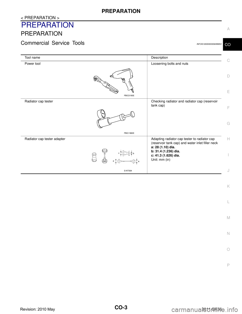
Power tool Loosening bolts and nuts
Radiator cap tester Checking radiator and radiator cap (reservoir tank cap)
Radiator cap tester adapter Adapting radiator cap tester to radiator cap (reservoir tank cap) and water inlet filler neck
a: 28 (1.10) dia.
b: 31.4 (1.236) dia.
c: 41.3 (1.626) dia.
Unit: mm (in)
PBIC0190E
PBIC1982E
S-NT564
Revision: 2010 May2011 QX56
Page 948 of 5598

CO-6
< SYMPTOM DIAGNOSIS >
OVERHEATING CAUSE ANALYSIS
SYMPTOM DIAGNOSIS
OVERHEATING CAUSE ANALYSIS
Troubleshooting ChartINFOID:0000000006289656
Symptom Check items
Cooling sys-
tem parts
malfunction Poor heat transfer
Water pump malfunction Worn or loose drive belt
—
Thermostat stuck closed —
Damaged fins
Dust contamination or pa-
per clogging
Physical damage
Clogged radiator cooling
tube Excess foreign material
(rust, dirt, sand, etc.)
Reduced air flow Cooling fan does not oper-
ate
Fan assembly —
High resistance to fan rota-
tion
Damaged fan blades
Damaged radiator shroud — — —
Improper engine coolant
mixture ratio ———
Poor engine coolant quality — Engine coolant density —
Insufficient engine coolant Engine coolant leakageCooling hose
Loose clamp
Cracked hose
Water pump Poor sealing
Radiator cap Loose
Poor sealing
Radiator O-ring for da
mage, deterio-
ration or improper fitting
Cracked radiator tank
Cracked radiator core
Reservoir tank Cracked reservoir tank
Overflowing reservoir tank Exhaust gas leakage into
cooling system Cylinder head deterioration
Cylinder head gasket deteri-
oration
Revision: 2010 May2011 QX56
Page 950 of 5598
CO-8
< PERIODIC MAINTENANCE >
ENGINE COOLANT
PERIODIC MAINTENANCE
ENGINE COOLANT
InspectionINFOID:0000000006289657
LEVEL
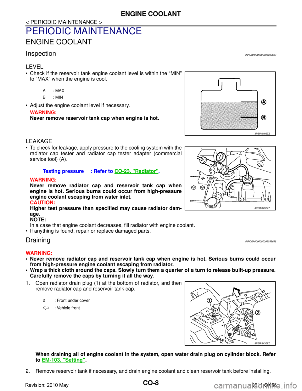
Check if the reservoir tank engine coolant level is within the “MIN”to “MAX” when the engine is cool.
Adjust the engine coolant level if necessary. WARNING:
Never remove reservoir tank cap when engine is hot.
LEAKAGE
To check for leakage, apply pressure to the cooling system with theradiator cap tester and radiator cap tester adapter (commercial
service tool) (A).
WARNING:
Never remove radiator cap and reservoir tank cap when
engine is hot. Serious burns could occur from high-pressure
engine coolant escaping from water inlet.
CAUTION:
Higher test pressure than specified may cause radiator dam-
age.
NOTE:
In a case that engine coolant decreas es, fill radiator with engine coolant.
If anything is found, repair or replace damaged parts.
DrainingINFOID:0000000006289658
WARNING:
Never remove radiator cap and reservoir tank cap when engine is hot. Serious burns could occur
from high-pressure engine co olant escaping from radiator.
Wrap a thick cloth around the caps. Slowly turn them a quarter of a turn to release built-up pressure.
Carefully remove the caps by turning it all the way.
1. Open radiator drain plug (1) at the bottom of radiator, and then remove radiator cap and reservoir tank cap.
When draining all of engine cool ant in the system, open water drai n plug on cylinder block. Refer
to EM-103, "
Setting".
2. Remove reservoir tank if necessary, and drain engine coolant and clean reservoir tank before installing.
A: MAX
B: MIN
JPBIA0102ZZ
Testing pressure : Refer to CO-23, "Radiator".
JPBIA3432ZZ
2 : Front under cover
: Vehicle front
JPBIA3430ZZ
Revision: 2010 May2011 QX56
Page 951 of 5598
ENGINE COOLANTCO-9
< PERIODIC MAINTENANCE >
C
DE
F
G H
I
J
K L
M A
CO
NP
O
3. Check drained engine coolant for contaminants such as rust, corrosion or discoloration.
If contaminated, flush the engine cooling system. Refer to CO-10, "
Flushing".
RefillingINFOID:0000000006289659
1. Install reservoir tank if removed, and radiator drain plug.
CAUTION:
Be sure to clean drain plug and install with new O-ring. Refer to CO-13, "
Exploded View".
If water drain plug on cylinder block is removed, close and tighten it. Refer to EM-107, "
Disassem-
bly and Assembly".
2. Check that each hose clamp is firmly tightened.
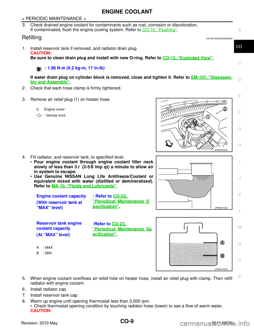
3. Remove air relief plug (1) on heater hose.
4. Fill radiator, and reservoir tank, to specified level. Pour engine coolant through engine coolant filler neck
slowly of less than 3 (2-5/8 lmp qt) a minute to allow air
in system to escape.
Use Genuine NISSAN Long Li fe Antifreeze/Coolant or
equivalent mixed with water (dis tilled or demineralized).
Refer to MA-10, "
Fluids and Lubricants".
5. When engine coolant overflows air relief hole on heater hos e, install air relief plug with clamp. Then refill
radiator with engine coolant.
6. Install radiator cap.
7. Install reservoir tank cap.
8. Warm up engine until opening thermostat less than 3,000 rpm. Check thermostat opening condition by touching radiat or hose (lower) to see a flow of warm water.
CAUTION: : 1.96 N·m (0.2 kg-m, 17 in-lb)
2. Engine cover
: Vehicle front
JPBIA3429ZZ
Engine coolant capacity : Refer to CO-23,
"PeriodicalMaintenanceS
pecification".
(With reservoir tank at
“MAX” level)JPBIA0412ZZ
Reservoir tank engine
coolant capacity :Refer to
CO-23,
"PeriodicalMaintenanceSp
ecification".
(At “MAX” level)
A : MAX
B: MIN
JPBIA0102ZZ
Revision: 2010 May2011 QX56
Page 952 of 5598
CO-10
< PERIODIC MAINTENANCE >
ENGINE COOLANT
Watch water temperature gauge so as not to overheat engine.
9. Stop the engine and cool down to less than approximately 50 °C (122 °F).
Cool down using fan to reduce the time.
If necessary, refill radiator up to filler neck with engine coolant.
10. Refill reservoir tank to “MAX” level line with engine coolant if necessary.
11. Repeat steps 6 through 10 two or more times with reservoir tank cap installed until engine coolant level no longer drops.
12. Check cooling system for leakage with engine running.
13. Warm up the engine, and check for sound of engine coolant flow while running engine from idle up to 3,000 rpm with heater temperature controller set at several position between “COOL” and “WARM”.
Sound may be noticeable at heater unit.
14. Repeat step 13 three times.
15. If sound is heard, bleed air from cooling system by repeating step 4, and steps from 6 to 14 until engine
coolant level no longer drops.
FlushingINFOID:0000000006289660
1. Install reservoir tank if removed, and radiator drain plug. CAUTION:
Be sure to clean drain plug and install with new O-ring. Refer to CO-13, "
Exploded View".
If water drain plug on cylinder block is removed, close and tighten it. Refer to EM-107, "
Disassem-
bly and Assembly".
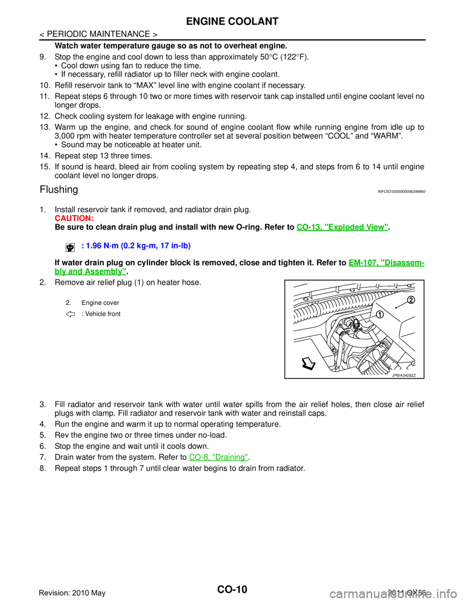
2. Remove air relief plug (1) on heater hose.
3. Fill radiator and reservoir tank with water until water spills from the air relief holes, then close air relief
plugs with clamp. Fill radiator and reservoir tank with water and reinstall caps.
4. Run the engine and warm it up to normal operating temperature.
5. Rev the engine two or three times under no-load.
6. Stop the engine and wait until it cools down.
7. Drain water from the system. Refer to CO-8, "
Draining".
8. Repeat steps 1 through 7 until clear water begins to drain from radiator. : 1.96 N·m (0.2 kg-m, 17 in-lb)
2. Engine cover
: Vehicle front
JPBIA3429ZZ
Revision: 2010 May2011 QX56
Page 953 of 5598
RADIATORCO-11
< PERIODIC MAINTENANCE >
C
DE
F
G H
I
J
K L
M A
CO
NP
O
RADIATOR
RESERVOIR TANK CAP
RESERVOIR TANK CAP : InspectionINFOID:0000000006289661
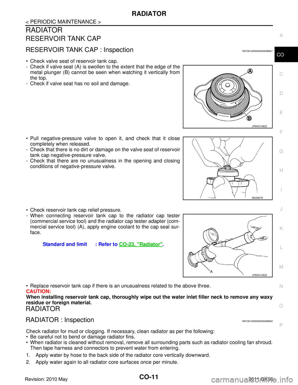
Check valve seat of reservoir tank cap.
- Check if valve seat (A) is swollen to the extent that the edge of the
metal plunger (B) cannot be seen when watching it vertically from
the top.
- Check if valve seat has no soil and damage.
Pull negative-pressure valve to open it, and check that it close completely when released.
- Check that there is no dirt or dam age on the valve seat of reservoir
tank cap negative-pressure valve.
- Check that there are no unusualness in the opening and closing conditions of negative-pressure valve.
Check reservoir tank cap relief pressure.
- When connecting reservoir tank cap to the radiator cap tester (commercial service tool) and the r adiator cap tester adapter (com-
mercial service tool) (A), apply engine coolant to the cap seal sur-
face.
Replace reservoir tank cap if there is an unusualness related to the above three.
CAUTION:
When installing reservoir tank cap , thoroughly wipe out the water inlet filler neck to remove any waxy
residue or foreign material.
RADIATOR
RADIATOR : InspectionINFOID:0000000006289662
Check radiator for mud or clogging. If neces sary, clean radiator as per the following:
Be careful not to bend or damage radiator fins.
When radiator is cleaned without removal, remove all surrounding parts such as radiator cooling fan shroud. Then tape harness and connectors to prevent water from entering.
1. Apply water by hose to the back side of the radiator core vertically downward.
2. Apply water again to all radiator core surfaces once per minute.
JPBIA0108ZZ
SMA967B
Standard and limit : Refer to CO-23, "Radiator".
JPBIA0109ZZ
Revision: 2010 May2011 QX56
Page 955 of 5598
RADIATORCO-13
< REMOVAL AND INSTALLATION >
C
DE
F
G H
I
J
K L
M A
CO
NP
O
REMOVAL AND INSTALLATION
RADIATOR
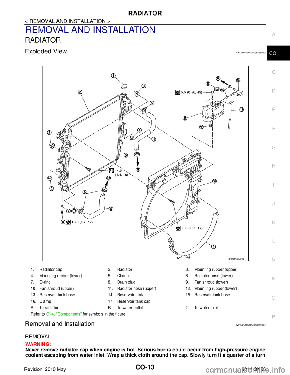
Exploded ViewINFOID:0000000006289663
Removal and InstallationINFOID:0000000006289664
REMOVAL
WARNING:
Never remove radiator cap when en
gine is hot. Serious burns could occur from high-pressure engine
coolant escaping from water inlet. Wrap a thick cloth around the cap. Slowly turn it a quarter of a turn
1. Radiator cap 2. Radiator 3. Mounting rubber (upper)
4. Mounting rubber (lower) 5. Clamp 6. Radiator hose (lower)
7. O-ring 8. Drain plug 9. Fan shroud (lower)
10. Fan shroud (upper) 11. Radiator hose (upper) 12. Mounting rubber (lower)
13. Reservoir tank hose 14. Reservoir tank 15. Reservoir tank hose
16. Clamp 17. Reservoir tank cap
A. To radiator B. To water outlet C. To water inlet
Refer to GI-4, "
Components" for symbols in the figure.
JPBIA3324GB
Revision: 2010 May2011 QX56
Page 956 of 5598
CO-14
< REMOVAL AND INSTALLATION >
RADIATOR
to release built-up pressure. Carefully remove radiator cap by turning it all the way. Note that the reser-
voir tank cap side is also under pressure.
1. Remove front under cover with power tool. Refer to EXT-25, "
Exploded View".
2. Remove engine cover. Refer to EM-25, "
Exploded View".
3. Drain engine coolant from radiator. Refer to CO-8, "
Draining".
CAUTION:
Perform this step when the engine is cold.
Never spill engine coolant on drive belts.
4. Remove radiator hose (lower).
5. Remove fan shroud (lower). Refer to CO-13, "
Exploded View".
6. Move reservoir tank to the position without the hindrance for work.
7. Remove radiator core support cover. Refer to DLK-220, "
Exploded View".
8. Remove fan shroud (upper), refer to following.
a. Remove EVAP hose mounting bolts and move harness to aside.
b. Move air cleaner case to the position without the hindrance for work. Refer to EM-27, "
Exploded View".
NOTE:
The air cleaner case connector is not required to be disconnected.
9. Remove radiator grille. Refer to EXT-19, "
Exploded View".
10. Move condenser to the position without the hindranc e for work with the following procedures. Refer to HA-
38, "Exploded View".
Remove mounting bolts and disconnect A/C piping from radiator.
Remove air guide from radiator. Refer to EXT-12, "
Exploded View".
Remove radiator mounting bolts.
11. Remove radiator hose (upper).
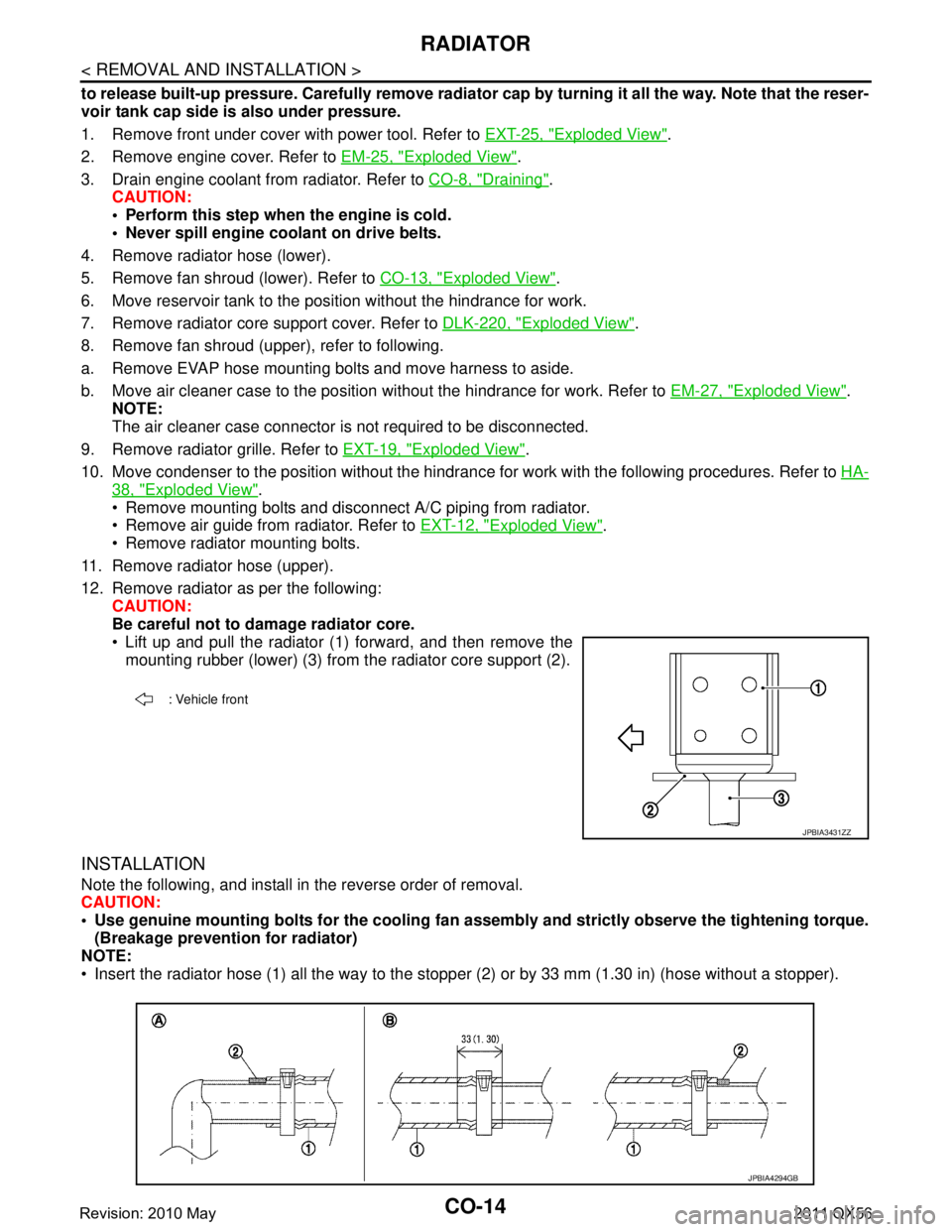
12. Remove radiator as per the following: CAUTION:
Be careful not to damage radiator core.
Lift up and pull the radiator (1) forward, and then remove themounting rubber (lower) (3) from the radiator core support (2).
INSTALLATION
Note the following, and install in the reverse order of removal.
CAUTION:
Use genuine mounting bolts for th e cooling fan assembly and strictly observe the tightening torque.
(Breakage prevention for radiator)
NOTE:
Insert the radiator hose (1) all the way to the st opper (2) or by 33 mm (1.30 in) (hose without a stopper).
: Vehicle front
JPBIA3431ZZ
JPBIA4294GB
Revision: 2010 May2011 QX56
Page 957 of 5598
RADIATORCO-15
< REMOVAL AND INSTALLATION >
C
DE
F
G H
I
J
K L
M A
CO
NP
O
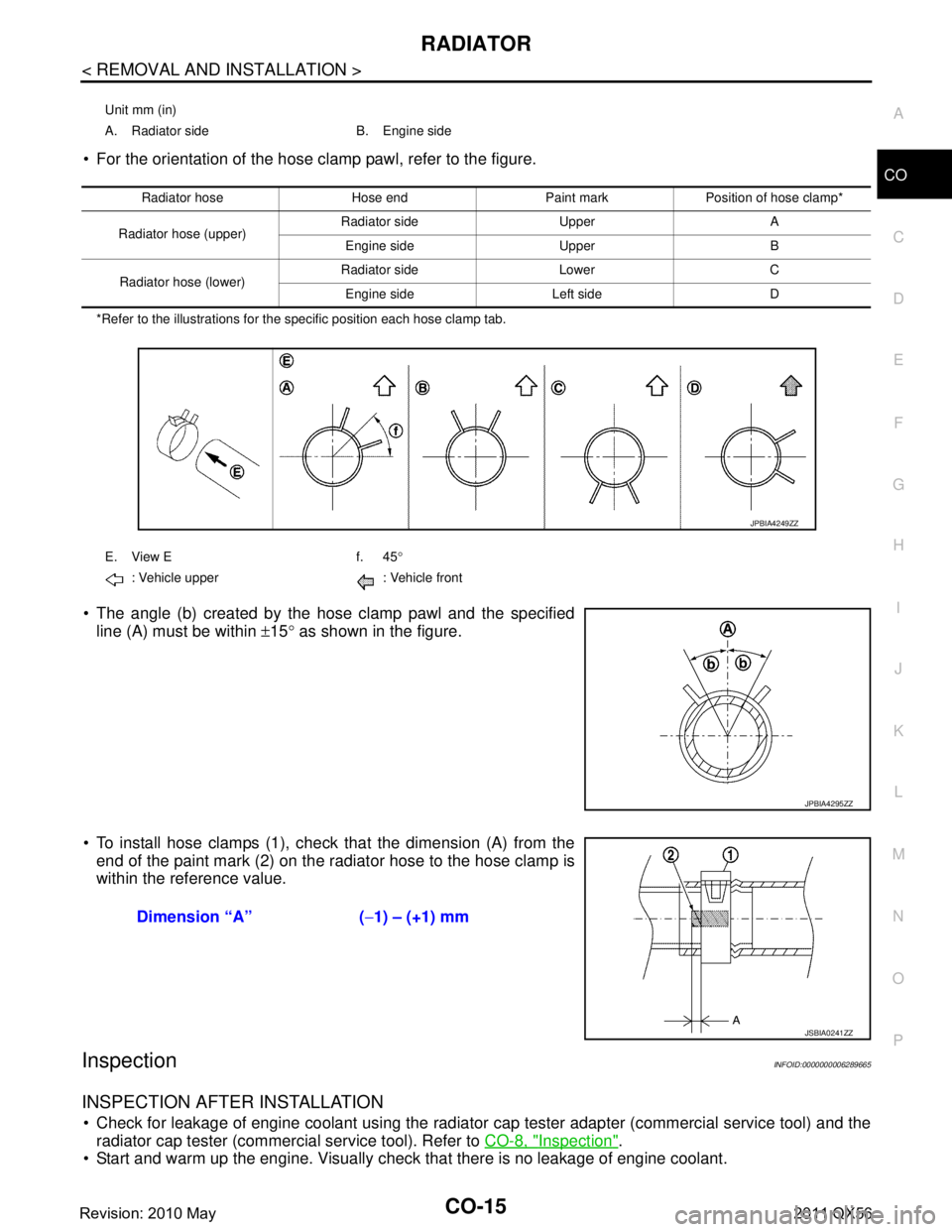
For the orientation of the hose clamp pawl, refer to the figure.
*Refer to the illustrations for the specific position each hose clamp tab.
The angle (b) created by the hose clamp pawl and the specified
line (A) must be within ±15 ° as shown in the figure.
To install hose clamps (1), check that the dimension (A) from the end of the paint mark (2) on the radiator hose to the hose clamp is
within the reference value.
InspectionINFOID:0000000006289665
INSPECTION AFTER INSTALLATION
Check for leakage of engine coolant using the radiator cap tester adapter (commercial service tool) and the
radiator cap tester (commercial service tool). Refer to CO-8, "
Inspection".
Start and warm up the engine. Visually check that there is no leakage of engine coolant.
Unit mm (in)
A. Radiator side B. Engine side
Radiator hose Hose end Paint mark Position of hose clamp*
Radiator hose (upper) Radiator side Upper A
Engine side Upper B
Radiator hose (lower) Radiator side Lower C
Engine side Left side D
E. View E f. 45 °
: Vehicle upper : Vehicle front
JPBIA4249ZZ
JPBIA4295ZZ
Dimension “A” ( −1) – (+1) mm
JSBIA0241ZZ
Revision: 2010 May2011 QX56