service INFINITI QX56 2011 Factory Service Manual
[x] Cancel search | Manufacturer: INFINITI, Model Year: 2011, Model line: QX56, Model: INFINITI QX56 2011Pages: 5598, PDF Size: 94.53 MB
Page 5044 of 5598
SERVICE DATA AND SPECIFICATIONS (SDS)
ST-57
< SERVICE DATA AND SPECIFICATIONS (SDS)
C
D E
F
H I
J
K L
M A
B
ST
N
O P
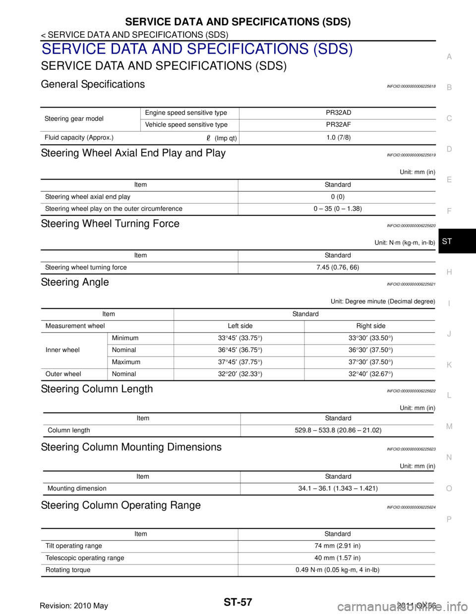
SERVICE DATA AND SPECIFICATIONS (SDS)
SERVICE DATA AND SPECIFICATIONS (SDS)
General SpecificationsINFOID:0000000006225618
Steering Wheel Axial End Play and PlayINFOID:0000000006225619
Unit: mm (in)
Steering Wheel Turning ForceINFOID:0000000006225620
Unit: N·m (kg-m, in-lb)
Steering AngleINFOID:0000000006225621
Unit: Degree minute (Decimal degree)
Steering Column LengthINFOID:0000000006225622
Unit: mm (in)
Steering Column Mounting DimensionsINFOID:0000000006225623
Unit: mm (in)
Steering Column Operating RangeINFOID:0000000006225624
Steering gear model Engine speed sensitive type PR32AD
Vehicle speed sensitive type PR32AF
Fluid capacity (Approx.) (lmp qt)1.0 (7/8)
Item Standard
Steering wheel axial end play 0 (0)
Steering wheel play on the outer circumference 0 – 35 (0 – 1.38)
Item Standard
Steering wheel turning force 7.45 (0.76, 66)
Item Standard
Measurement wheel Left side Right side
Inner wheel Minimum 33
°45 ′ (33.75 °)33 °30 ′ (33.50 °)
Nominal 36 °45 ′ (36.75 °)36 °30 ′ (37.50 °)
Maximum 37 °45 ′ (37.75 °)37 °30 ′ (37.50 °)
Outer wheel Nominal 32 °20 ′ (32.33 °)32 °40 ′ (32.67 °)
Item Standard
Column length 529.8 – 533.8 (20.86 – 21.02)
Item Standard
Mounting dimension 34.1 – 36.1 (1.343 – 1.421)
Item Standard
Tilt operating range 74 mm (2.91 in)
Telescopic operating range 40 mm (1.57 in)
Rotating torque 0.49 N· m (0.05 kg-m, 4 in-lb)
Revision: 2010 May2011 QX56
Page 5045 of 5598

ST-58
< SERVICE DATA AND SPECIFICATIONS (SDS)
SERVICE DATA AND SPECIFICATIONS (SDS)
Steering Shaft Sliding Range
INFOID:0000000006225625
Unit: mm (in)
Rack Sliding ForceINFOID:0000000006225626
Unit: N (kg, lb)
Rack StrokeINFOID:0000000006225627
Unit: mm (in)
Socket Swing Force and Rotating TorqueINFOID:0000000006225628
SWING FORCE
Unit: N (kg, lb)
ROTATING TORQUE
Unit: N·m (kg-m, in-lb)
Socket Axial End PlayINFOID:0000000006225629
Unit: mm (in)
Inner Socket LengthINFOID:0000000006225630
Unit: mm (in)
Relief Oil PressureINFOID:0000000006225631
Unit: kPa (bar, kg/cm2, psi)
Item Standard
Sliding range 47 (1.85)
Steering shaft length (extended position) 393 (15.47) or less
Steering shaft runout 1.5 (0.059) or less
Item Standard
Rack sliding force 249.6 – 308.4 (25.5 – 31.4, 56.2 – 69.3)
Item Standard
Rack neutral position, dimension 83.5 (3.287)
Item Spring balance
Outer socket 10.0 – 36.7 (1.02 – 3.74, 2.25 – 8.25)
Inner socket 19.4 – 32.3 (1.98 – 3.29, 4.37 – 7.26)
Item Standard
Outer socket 0.3 – 2.9 (0.03 – 0.3, 2.7 – 26)
Item Standard
Outer socket 0.5 (0.02) or less
Inner socket 0.2 (0.008) or less
Item Standard
Rack neutral position, dimension 110.8 (4.36)
Item Standard
Relief oil pressure 9,500 – 10,300 (95 – 103, 96.9 – 105.1, 1,378 – 1,494)
Revision: 2010 May2011 QX56
Page 5047 of 5598
STC-2
< PRECAUTION >
PRECAUTIONS
PRECAUTION
PRECAUTIONS
Precaution for Supplemental Restraint System (SRS) "AIR BAG" and "SEAT BELT
PRE-TENSIONER"
INFOID:0000000006303358
The Supplemental Restraint System such as “A IR BAG” and “SEAT BELT PRE-TENSIONER”, used along
with a front seat belt, helps to reduce the risk or severi ty of injury to the driver and front passenger for certain
types of collision. This system includes seat belt switch inputs and dual stage front air bag modules. The SRS
system uses the seat belt switches to determine the front air bag deployment, and may only deploy one front
air bag, depending on the severity of a collision and w hether the front occupants are belted or unbelted.
Information necessary to service the system safely is included in the “SRS AIR BAG” and “SEAT BELT” of this
Service Manual.
WARNING:
• To avoid rendering the SRS inopera tive, which could increase the risk of personal injury or death in
the event of a collision that would result in air bag inflation, all maintenance must be performed by
an authorized NISS AN/INFINITI dealer.
Improper maintenance, including in correct removal and installation of the SRS, can lead to personal
injury caused by unintent ional activation of the system. For re moval of Spiral Cable and Air Bag
Module, see the “SRS AIR BAG”.
Do not use electrical test equipmen t on any circuit related to the SRS unless instructed to in this
Service Manual. SRS wiring harnesses can be identi fied by yellow and/or orange harnesses or har-
ness connectors.
PRECAUTIONS WHEN USING POWER TOOLS (AIR OR ELECTRIC) AND HAMMERS
WARNING:
When working near the Air Bag Diagnosis Sensor Unit or other Air Bag System sensors with the ignition ON or engine running, DO NOT use air or electric power tools or strike near the sensor(s)
with a hammer. Heavy vibration could activate the sensor(s) and deploy the air bag(s), possibly
causing serious injury.
When using air or electric power tools or hammers , always switch the ignition OFF, disconnect the
battery, and wait at least 3 minu tes before performing any service.
Precaution Necessary for Steering W heel Rotation after Battery Disconnect
INFOID:0000000006303360
NOTE:
Before removing and installing any control units, first tu rn the push-button ignition switch to the LOCK posi-
tion, then disconnect bot h battery cables.
After finishing work, confirm that all control unit connectors are connected properly, then re-connect both
battery cables.
Always use CONSULT-III to perform self-diagnosis as a part of each function inspection after finishing work.
If a DTC is detected, perform trouble diagnos is according to self-diagnosis results.
For vehicle with steering lock unit, if the battery is disconnected or discharged, the steering wheel will lock and
cannot be turned.
If turning the steering wheel is required with the bat tery disconnected or discharged, follow the operation pro-
cedure below before starting the repair operation.
OPERATION PROCEDURE
1. Connect both battery cables. NOTE:
Supply power using jumper cables if battery is discharged.
2. Turn the push-button ignition switch to ACC position. (At this time, the steering lock will be released.)
3. Disconnect both battery cables. The steering lock wi ll remain released with both battery cables discon-
nected and the steering wheel can be turned.
4. Perform the necessary repair operation.
Revision: 2010 May2011 QX56
Page 5069 of 5598

STR-1
ENGINE
C
DE
F
G H
I
J
K L
M
SECTION STR
A
STR
N
O P
CONTENTS
STARTING SYSTEM
PRECAUTION ................ ...............................2
PRECAUTIONS .............................................. .....2
Precaution for Supplemental Restraint System
(SRS) "AIR BAG" and "SEAT BELT PRE-TEN-
SIONER" ............................................................. ......
2
Precaution Necessary for Steering Wheel Rota-
tion after Battery Disconnect .....................................
2
PREPARATION ............................................4
PREPARATION .............................................. .....4
Special Service Tools .......................................... ......4
Commercial Service Tools ........................................4
SYSTEM DESCRIPTION ..............................5
COMPONENT PARTS ................................... .....5
Component Parts Location .................................. ......5
Component Description ............................................5
SYSTEM ..............................................................6
System Diagram .................................................. ......6
System Description ...................................................6
WIRING DIAGRAM .......................................7
STARTING SYSTEM ...................................... .....7
Wiring Diagram ................................................... ......7
BASIC INSPECTION ...................................11
DIAGNOSIS AND REPAIR WORKFLOW ........11
Work Flow ............................................................ ....11
DTC/CIRCUIT DIAGNOSIS .........................14
B TERMINAL CIRCUIT .....................................14
Diagnosis Procedure ........................................... ....14
S CONNECTOR CIRCUIT .................................15
Diagnosis Procedure ...............................................15
SYMPTOM DIAGNOSIS ..............................16
STARTING SYSTEM .........................................16
Symptom Table ................................................... ....16
REMOVAL AND INSTALLATION ...............17
STARTER MOTOR ...........................................17
Exploded View ..................................................... ....17
Removal and Installation .........................................18
Inspection ................................................................18
SERVICE DATA AND SPECIFICATIONS
(SDS) ............... .............................................
20
SERVICE DATA AND SPECIFICATIONS
(SDS) .................................................................
20
Starter Motor .......................................................
Revision: 2010 May2011 QX56
Page 5070 of 5598
STR-2
< PRECAUTION >
PRECAUTIONS
PRECAUTION
PRECAUTIONS
Precaution for Supplemental Restraint System (SRS) "AIR BAG" and "SEAT BELT
PRE-TENSIONER"
INFOID:0000000006275515
The Supplemental Restraint System such as “A IR BAG” and “SEAT BELT PRE-TENSIONER”, used along
with a front seat belt, helps to reduce the risk or severi ty of injury to the driver and front passenger for certain
types of collision. This system includes seat belt switch inputs and dual stage front air bag modules. The SRS
system uses the seat belt switches to determine the front air bag deployment, and may only deploy one front
air bag, depending on the severity of a collision and w hether the front occupants are belted or unbelted.
Information necessary to service the system safely is included in the “SRS AIR BAG” and “SEAT BELT” of this
Service Manual.
WARNING:
• To avoid rendering the SRS inopera tive, which could increase the risk of personal injury or death in
the event of a collision that would result in air bag inflation, all maintenance must be performed by
an authorized NISS AN/INFINITI dealer.
Improper maintenance, including in correct removal and installation of the SRS, can lead to personal
injury caused by unintent ional activation of the system. For re moval of Spiral Cable and Air Bag
Module, see the “SRS AIR BAG”.
Do not use electrical test equipmen t on any circuit related to the SRS unless instructed to in this
Service Manual. SRS wiring harnesses can be identi fied by yellow and/or orange harnesses or har-
ness connectors.
PRECAUTIONS WHEN USING POWER TOOLS (AIR OR ELECTRIC) AND HAMMERS
WARNING:
When working near the Air Bag Diagnosis Sensor Unit or other Air Bag System sensors with the ignition ON or engine running, DO NOT use air or electric power tools or strike near the sensor(s)
with a hammer. Heavy vibration could activate the sensor(s) and deploy the air bag(s), possibly
causing serious injury.
When using air or electric power tools or hammers , always switch the ignition OFF, disconnect the
battery, and wait at least 3 minu tes before performing any service.
Precaution Necessary for Steering W heel Rotation after Battery Disconnect
INFOID:0000000006275516
NOTE:
Before removing and installing any control units, first tu rn the push-button ignition switch to the LOCK posi-
tion, then disconnect bot h battery cables.
After finishing work, confirm that all control unit connectors are connected properly, then re-connect both
battery cables.
Always use CONSULT-III to perform self-diagnosis as a part of each function inspection after finishing work.
If a DTC is detected, perform trouble diagnos is according to self-diagnosis results.
For vehicle with steering lock unit, if the battery is disconnected or discharged, the steering wheel will lock and
cannot be turned.
If turning the steering wheel is required with the bat tery disconnected or discharged, follow the operation pro-
cedure below before starting the repair operation.
OPERATION PROCEDURE
1. Connect both battery cables. NOTE:
Supply power using jumper cables if battery is discharged.
2. Turn the push-button ignition switch to ACC position. (At this time, the steering lock will be released.)
3. Disconnect both battery cables. The steering lock wi ll remain released with both battery cables discon-
nected and the steering wheel can be turned.
4. Perform the necessary repair operation.
Revision: 2010 May2011 QX56
Page 5072 of 5598
STR-4
< PREPARATION >
PREPARATION
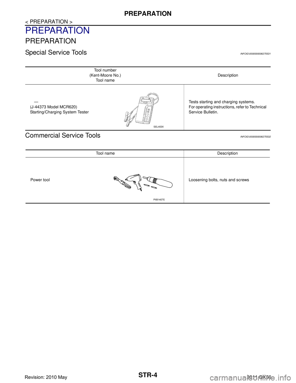
PREPARATION
PREPARATION
Special Service ToolsINFOID:0000000006275531
Commercial Service ToolsINFOID:0000000006275532
Tool number
(Kent-Moore No.) Tool name Description
—
(J-44373 Model MCR620)
Starting/Charging System Tester Tests starting and charging systems.
For operating instructio
ns, refer to Technical
Service Bulletin.
SEL403X
Tool name Description
Power tool Loosening bolts, nuts and screws
PIIB1407E
Revision: 2010 May2011 QX56
Page 5080 of 5598
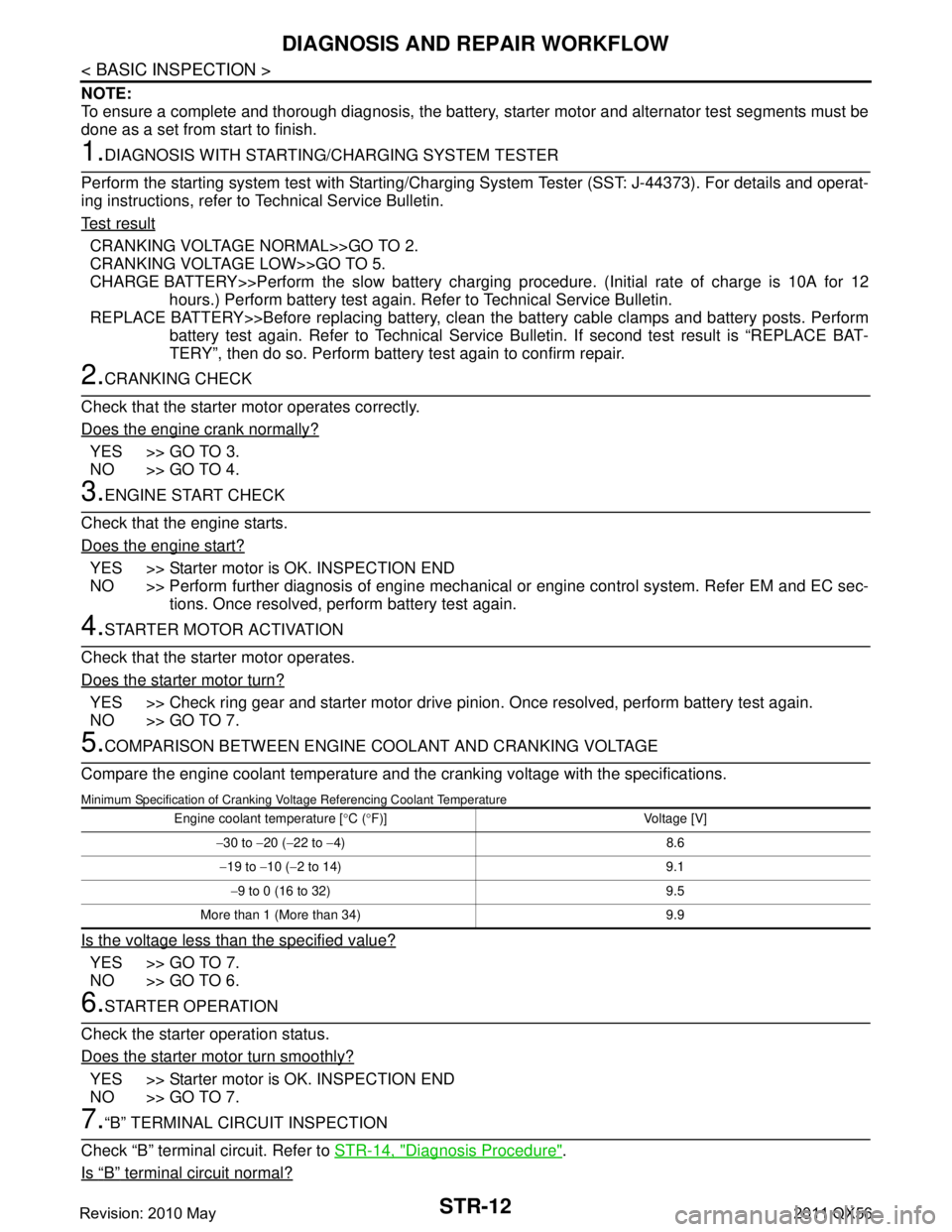
STR-12
< BASIC INSPECTION >
DIAGNOSIS AND REPAIR WORKFLOW
NOTE:
To ensure a complete and thorough diagnosis, the battery, starter motor and alternator test segments must be
done as a set from start to finish.
1.DIAGNOSIS WITH STARTING /CHARGING SYSTEM TESTER
Perform the starting system test with Starting/Char ging System Tester (SST: J-44373). For details and operat-
ing instructions, refer to Technical Service Bulletin.
Te s t r e s u l t
CRANKING VOLTAGE NORMAL>>GO TO 2.
CRANKING VOLTAGE LOW>>GO TO 5.
CHARGE BATTERY>>Perform the slow battery charging procedure. (Initial rate of charge is 10A for 12
hours.) Perform battery test again. Re fer to Technical Service Bulletin.
REPLACE BATTERY>>Before replacing battery, clean t he battery cable clamps and battery posts. Perform
battery test again. Refer to Technical Service Bu lletin. If second test result is “REPLACE BAT-
TERY”, then do so. Perform battery test again to confirm repair.
2.CRANKING CHECK
Check that the starter motor operates correctly.
Does the engine crank normally?
YES >> GO TO 3.
NO >> GO TO 4.
3.ENGINE START CHECK
Check that the engine starts.
Does the engine start?
YES >> Starter motor is OK. INSPECTION END
NO >> Perform further diagnosis of engine mechanical or engine control system. Refer EM and EC sec-
tions. Once resolved, perform battery test again.
4.STARTER MOTOR ACTIVATION
Check that the starter motor operates.
Does the starter motor turn?
YES >> Check ring gear and starter motor drive pinion. Once resolved, perform battery test again.
NO >> GO TO 7.
5.COMPARISON BETWEEN ENGINE COOLANT AND CRANKING VOLTAGE
Compare the engine coolant temperature and the cranking voltage with the specifications.
Minimum Specification of Cranking Voltage Referencing Coolant Temperature
Is the voltage less than the specified value?
YES >> GO TO 7.
NO >> GO TO 6.
6.STARTER OPERATION
Check the starter operation status.
Does the starter motor turn smoothly?
YES >> Starter motor is OK. INSPECTION END
NO >> GO TO 7.
7.“B” TERMINAL CIRCUIT INSPECTION
Check “B” terminal circuit. Refer to STR-14, "
Diagnosis Procedure".
Is
“B” terminal circuit normal?
Engine coolant temperature [ °C ( °F)] Voltage [V]
− 30 to −20 ( −22 to −4) 8.6
− 19 to −10 ( −2 to 14) 9.1
− 9 to 0 (16 to 32) 9.5
More than 1 (More than 34) 9.9
Revision: 2010 May2011 QX56
Page 5081 of 5598
DIAGNOSIS AND REPAIR WORKFLOWSTR-13
< BASIC INSPECTION >
C
DE
F
G H
I
J
K L
M A
STR
NP
O
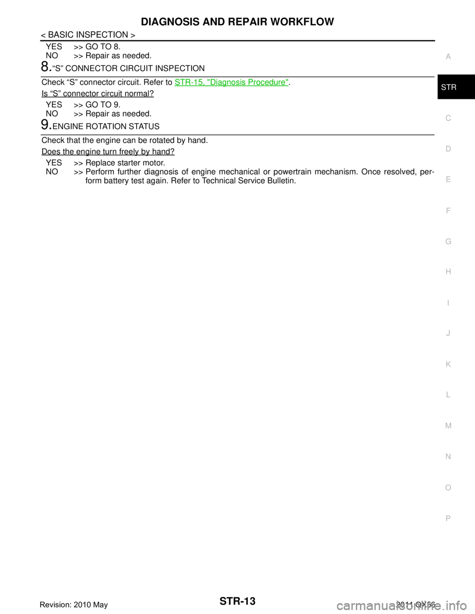
YES >> GO TO 8.
NO >> Repair as needed.
8.“S” CONNECTOR CIRCUIT INSPECTION
Check “S” connector circuit. Refer to STR-15, "
Diagnosis Procedure".
Is
“S” connector circuit normal?
YES >> GO TO 9.
NO >> Repair as needed.
9.ENGINE ROTATION STATUS
Check that the engine can be rotated by hand.
Does the engine turn freely by hand?
YES >> Replace starter motor.
NO >> Perform further diagnosis of engine mechanical or powertrain mechanism. Once resolved, per-
form battery test again. Refer to Technical Service Bulletin.
Revision: 2010 May2011 QX56
Page 5088 of 5598

STR-20
< SERVICE DATA AND SPECIFICATIONS (SDS)
SERVICE DATA AND SPECIFICATIONS (SDS)
SERVICE DATA AND SPECIFICATIONS (SDS)
SERVICE DATA AND SPECIFICATIONS (SDS)
Starter MotorINFOID:0000000006275530
Ty p eM001T30671
MITSUBISHI make
Reduction gear type
System voltage [V] 12
No-load Terminal voltage [V] 11
Current [A] Less than 120
Revolution [rpm] More than 3,220
Minimum diameter of commutator [mm. (in)] 28.8 (1.134)
Minimum length of brush [mm. (in)] 10.0 (0.394)
Brush spring tension [N (kg, lb.)] 23.4 – 31.6
(2.4, 5.3 – 3.2, 7.1)
Clearance between bearing metal and armature shaft [mm. (in)] Less than 0.2 (0.008)
Clearance between pinion front edge and pinion stopper [mm. (in)] 0.5 – 2.0 (0.02 – 0.079)
Revision: 2010 May2011 QX56
Page 5089 of 5598

TM-1
TRANSMISSION & DRIVELINE
CEF
G H
I
J
K L
M
SECTION TM
A
B
TM
N
O P
CONTENTS
TRANSAXLE & TRANSMISSION
7AT: RE7R01B
PRECAUTION ................ ...............................
6
PRECAUTIONS .............................................. .....6
Precaution for Supplemental Restraint System
(SRS) "AIR BAG" and "SEAT BELT PRE-TEN-
SIONER" ............................................................. ......
6
General Precautions .................................................6
Service Notice or Precaution .....................................7
PREPARATION ............................................8
PREPARATION .............................................. .....8
Special Service Tool ........................................... ......8
Commercial Service Tool ..........................................9
SYSTEM DESCRIPTION .............................10
COMPONENT PARTS ................................... ....10
A/T CONTROL SYSTEM ...........................................10
A/T CONTROL SYSTEM : Component Parts Lo-
cation ................................................................... ....
10
A/T CONTROL SYSTEM : Component Descrip-
tion ...................................................................... ....
11
A/T CONTROL SYSTEM : TCM .............................12
A/T CONTROL SYSTEM : Transmission Range
Switch .................................................................. ....
12
A/T CONTROL SYSTEM : Input Speed Sensor .....12
A/T CONTROL SYSTEM : Output Speed Sensor ....12
A/T CONTROL SYSTEM : A/ T Fluid Temperature
Sensor ................................................................. ....
12
A/T CONTROL SYSTEM : Input Clutch Solenoid
Valve ................................................................... ....
12
A/T CONTROL SYSTEM : Front Brake Solenoid
Valve ................................................................... ....
12
A/T CONTROL SYSTEM : Direct Clutch Solenoid
Valve ................................................................... ....
12
A/T CONTROL SYSTEM : High and Low Reverse
Clutch Solenoid Valve ......................................... ....
13
A/T CONTROL SYSTEM : Low Brake Solenoid
Valve .................................................................... ....
13
A/T CONTROL SYSTEM : Anti-interlock Solenoid
Valve ........................................................................
13
A/T CONTROL SYSTEM : 2346 Brake Solenoid
Valve ........................................................................
13
A/T CONTROL SYSTEM : Torque Converter
Clutch Solenoid Valve ......................................... ....
13
A/T CONTROL SYSTEM : Line Pressure Solenoid
Valve .................................................................... ....
13
A/T CONTROL SYSTEM : Accelerator Pedal Po-
sition Sensor ........................................................ ....
13
A/T CONTROL SYSTEM : Manual Mode Switch ....13
A/T CONTROL SYSTEM : To w Mode Switch .........14
A/T CONTROL SYSTEM : A/T CHECK Indicator
Lamp .................................................................... ....
14
A/T CONTROL SYSTEM : Tow Mode Indicator
Lamp .................................................................... ....
14
A/T CONTROL SYSTEM : Selector Lever Position
Indicator ............................................................... ....
14
A/T SHIFT LOCK SYSTEM ................................... ....14
A/T SHIFT LOCK SYSTEM : Component Parts
Location ...................................................................
15
A/T SHIFT LOCK SYSTEM : Component Descrip-
tion ...........................................................................
15
STRUCTURE AND OPERATION .....................16
TRANSMISSION .................................................... ....16
TRANSMISSION : Cross-Sectional View ................16
TRANSMISSION : System Diagram ........................18
TRANSMISSION : System Description ...................18
TRANSMISSION : Component Description .............41
FLUID COOLER & FLUID WARMER SYSTEM .... ....41
FLUID COOLER & FLUID WARMER SYSTEM :
System Description ..................................................
41
SYSTEM ............................................................44
A/T CONTROL SYSTEM ....................................... ....44
Revision: 2010 May2011 QX56