service INFINITI QX56 2011 Factory Service Manual
[x] Cancel search | Manufacturer: INFINITI, Model Year: 2011, Model line: QX56, Model: INFINITI QX56 2011Pages: 5598, PDF Size: 94.53 MB
Page 5455 of 5598
PREPARATIONWT-5
< PREPARATION >
C
DF
G H
I
J
K L
M A
B
WT
N
O P
PREPARATION
PREPARATION
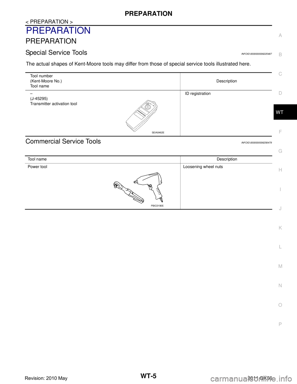
Special Service ToolsINFOID:0000000006225487
The actual shapes of Kent-Moore tools may differ fr om those of special service tools illustrated here.
Commercial Service ToolsINFOID:0000000006256479
Tool number
(Kent-Moore No.)
Tool name Description
–
(J-45295)
Transmitter activation tool ID registration
SEIA0462E
To o l n a m e
Description
Power tool Loosening wheel nuts
PBIC0190E
Revision: 2010 May2011 QX56
Page 5461 of 5598

SYSTEMWT-11
< SYSTEM DESCRIPTION >
C
DF
G H
I
J
K L
M A
B
WT
N
O P
If there is no response for approximately 15 seconds or mo re after inflating the tires, cancel the use of the
tire inflation indicator function or move the vehicle approximately 1 m (3.2 ft) backward or forward to try
again. The air filler pressure may be weak or out of service area.
Revision: 2010 May2011 QX56
Page 5477 of 5598
ADDITIONAL SERVICE WHEN REPLACING LOW TIRE PRESSURE WARNING
CONTROL UNIT
WT-27
< BASIC INSPECTION >
C
DF
G H
I
J
K L
M A
B
WT
N
O P
ADDITIONAL SERVICE WHEN RE PLACING LOW TIRE PRESSURE
WARNING CONTROL UNIT
DescriptionINFOID:0000000006225502
When replacing low tire pressure warning contro l unit, transmitter ID registration is required.
Work ProcedureINFOID:0000000006225503
ADJUST THE NEUTRAL POSITION OF STEERING ANGLE SENSOR
1.PERFORM TRANSMITTER ID REGISTRATION
Perform transmitter ID registration.
>> Refer to WT-29, "
Work Procedure".
Revision: 2010 May2011 QX56
Page 5509 of 5598
TIRE INFLATION INDICATOR DOES NOT ACTIVATEWT-59
< SYMPTOM DIAGNOSIS >
C
DF
G H
I
J
K L
M A
B
WT
N
O P
TIRE INFLATION INDICATOR DOES NOT ACTIVATE
DescriptionINFOID:0000000006225540
The tire inflation indicator does not function while inflat ing a tire when the A/T shift selector position is in P-
range with the ignition switch ON or with the engine started.
NOTE:
After starting to inflate the tire, it takes a few seconds for the tire inflation indicator to function.
If there is no response for approximately 15 seconds or mo re after inflating the tires, cancel the use of the
tire inflation indicator function or move the vehicle approximately 1 m (3.2 ft) backward or forward to try
again. The air filler pressure may be weak or out of service area.
For tire inflation indicator, Refer to WT-10, "
Tire Inflation Indicator Function".
Diagnosis ProcedureINFOID:0000000006225541
1. LOCATION CHANGE
Move the vehicle to other area and repeat the procedure of the tire inflation indicator function. Refer to WT-10,
"Tire Inflation Indicator Function".
Is the function normal?
YES >> Normal (the tire inflation indicator may not operate, depending on reception condition.)
NO >> GO TO 2.
2.PERFORM LOW TIRE PRESSURE WARNI NG CONTROL UNIT SELF-DIAGNOSIS
With CONSULT-III
1. Drive for 10 minutes at a speed of 40 km/h (25 MPH) or more.
2. Stop the vehicle.
3. Perform self-diagnosis for “AIR PRESSURE MONITOR”.
Is any DTC detected?
YES >> Perform trouble diagnosis for detected DTC. Refer to WT-18, "DTC Index".
NO >> GO TO 3.
3.CHECK HAZARD WARNING LAMP OPERATION
Check hazard warning lamp operation with hazard switch.
Does the hazard warning lamp blink?
YES >> GO TO 4.
NO >> Perform trouble diagnosis for the hazard warning lamp. Refer to EXL-113, "
Symptom Table".
4.PERFORM TCM SELF-DIAGNOSIS
With CONSULT-III
Perform self-diagnosis for “TRANSMISSION”.
Is any DTC detected?
YES >> Check malfunctioning circuit. Refer to TM-78, "DTC Index".
NO >> GO TO 5.
5.CHECK HORN OPERATION
Check horn operation. Refer to SEC-143, "
ComponentFunctionCheck".
Is the operation normal?
YES >> GO TO 6.
NO >> Repair or replace error-detected parts.
6.PERFORM BCM SELF-DIAGNOSIS
With CONSULT-III
Perform self-diagnosis for “BCM”.
Is any DTC detected?
YES >> Check malfunctioning circuit. Refer to BCS-57, "DTCIndex".
NO >> Replace low tire pressure warning control unit. Refer to WT-65, "
Removal and Installation".
Revision: 2010 May2011 QX56
Page 5513 of 5598
ROAD WHEELWT-63
< PERIODIC MAINTENANCE >
C
DF
G H
I
J
K L
M A
B
WT
N
O P
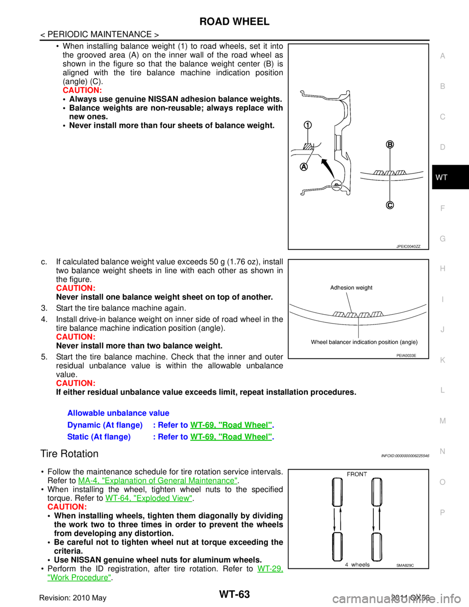
When installing balance weight (1) to road wheels, set it into the grooved area (A) on the inner wall of the road wheel as
shown in the figure so that the balance weight center (B) is
aligned with the tire balance machine indication position
(angle) (C).
CAUTION:
Always use genuine NISSAN ad hesion balance weights.
Balance weights are non-re usable; always replace with
new ones.
Never install more than four sheets of balance weight.
c. If calculated balance weight value exceeds 50 g (1.76 oz), install two balance weight sheets in line with each other as shown in
the figure.
CAUTION:
Never install one balance weight sheet on top of another.
3. Start the tire balance machine again.
4. Install drive-in balance weight on inner side of road wheel in the tire balance machine indication position (angle).
CAUTION:
Never install more than two balance weight.
5. Start the tire balance machine. Check that the inner and outer residual unbalance value is within the allowable unbalance
value.
CAUTION:
If either residual unbalan ce value exceeds limit, repeat installation procedures.
Tire RotationINFOID:0000000006225546
Follow the maintenance schedule for tire rotation service intervals.
Refer to MA-4, "
Explanation of General Maintenance".
When installing the wheel, tighten wheel nuts to the specified torque. Refer to WT-64, "
Exploded View".
CAUTION:
When installing wheels, tighte n them diagonally by dividing
the work two to three times in order to prevent the wheels
from developing any distortion.
Be careful not to tighten wh eel nut at torque exceeding the
criteria.
Use NISSAN genuine wheel nuts for aluminum wheels.
Perform the ID registration, after tire rotation. Refer to WT-29,
"Work Procedure".
JPEIC0040ZZ
Allowable unbalance value
Dynamic (At flange) : Refer to WT-69, "
Road Wheel".
Static (At flange) : Refer to WT-69, "
Road Wheel".
PEIA0033E
SMA829C
Revision: 2010 May2011 QX56
Page 5519 of 5598
SERVICE DATA AND SPECIFICATIONS (SDS)
WT-69
< SERVICE DATA AND SPECIFICATIONS (SDS)
C
D F
G H
I
J
K L
M A
B
WT
N
O P
SERVICE DATA AND SPECIFICATIONS (SDS)
SERVICE DATA AND SPECIFICATIONS (SDS)
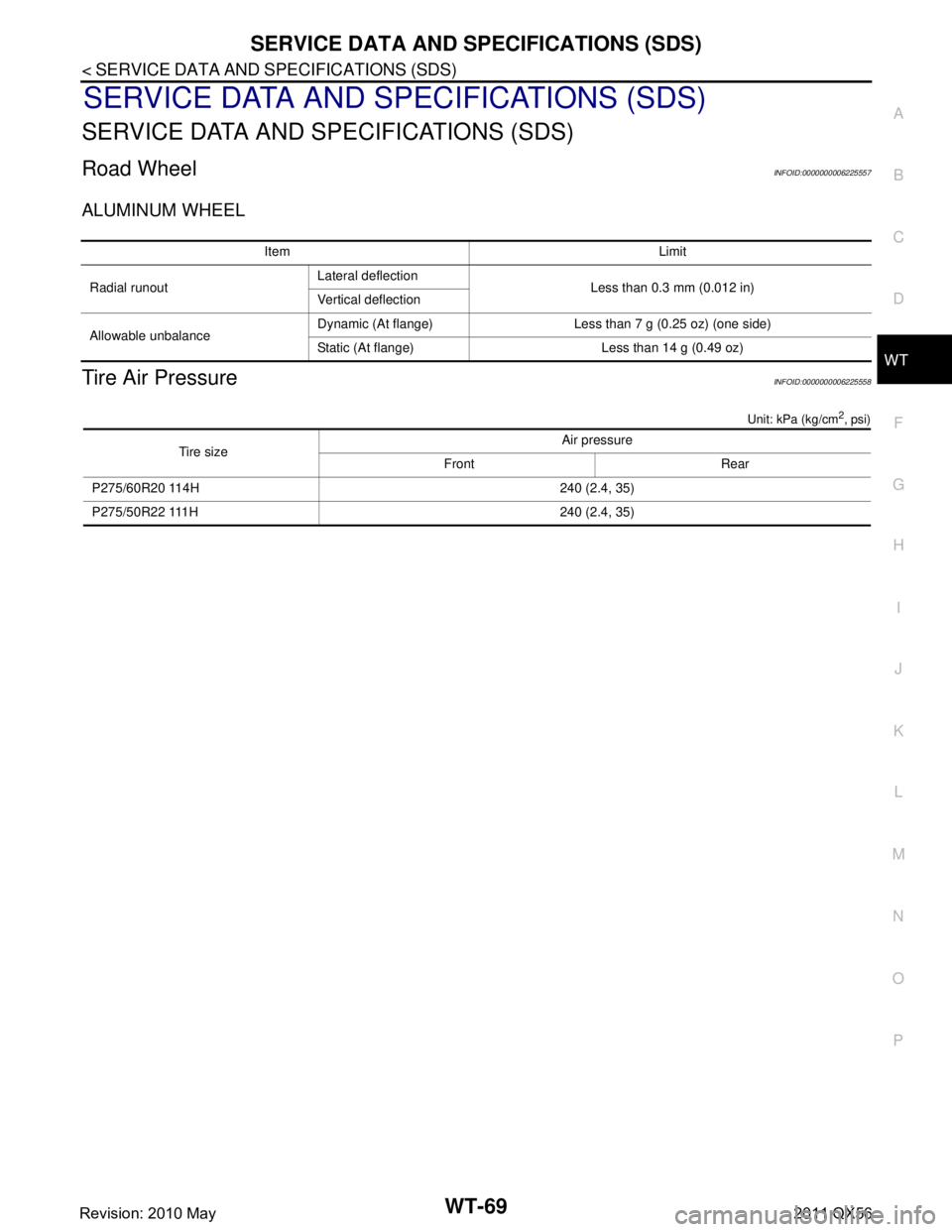
Road WheelINFOID:0000000006225557
ALUMINUM WHEEL
Tire Air PressureINFOID:0000000006225558
Unit: kPa (kg/cm2, psi)
Item Limit
Radial runout Lateral deflection
Less than 0.3 mm (0.012 in)
Vertical deflection
Allowable unbalance Dynamic (At flange) Less than 7 g (0.25 oz) (one side)
Static (At flange) Less than 14 g (0.49 oz)
Tire size Air pressure
Front Rear
P275/60R20 114H 240 (2.4, 35)
P275/50R22 111H 240 (2.4, 35)
Revision: 2010 May2011 QX56
Page 5522 of 5598
PRECAUTIONSWW-3
< PRECAUTION >
C
DE
F
G H
I
J
K
M A
B
WW
N
O P
PRECAUTION
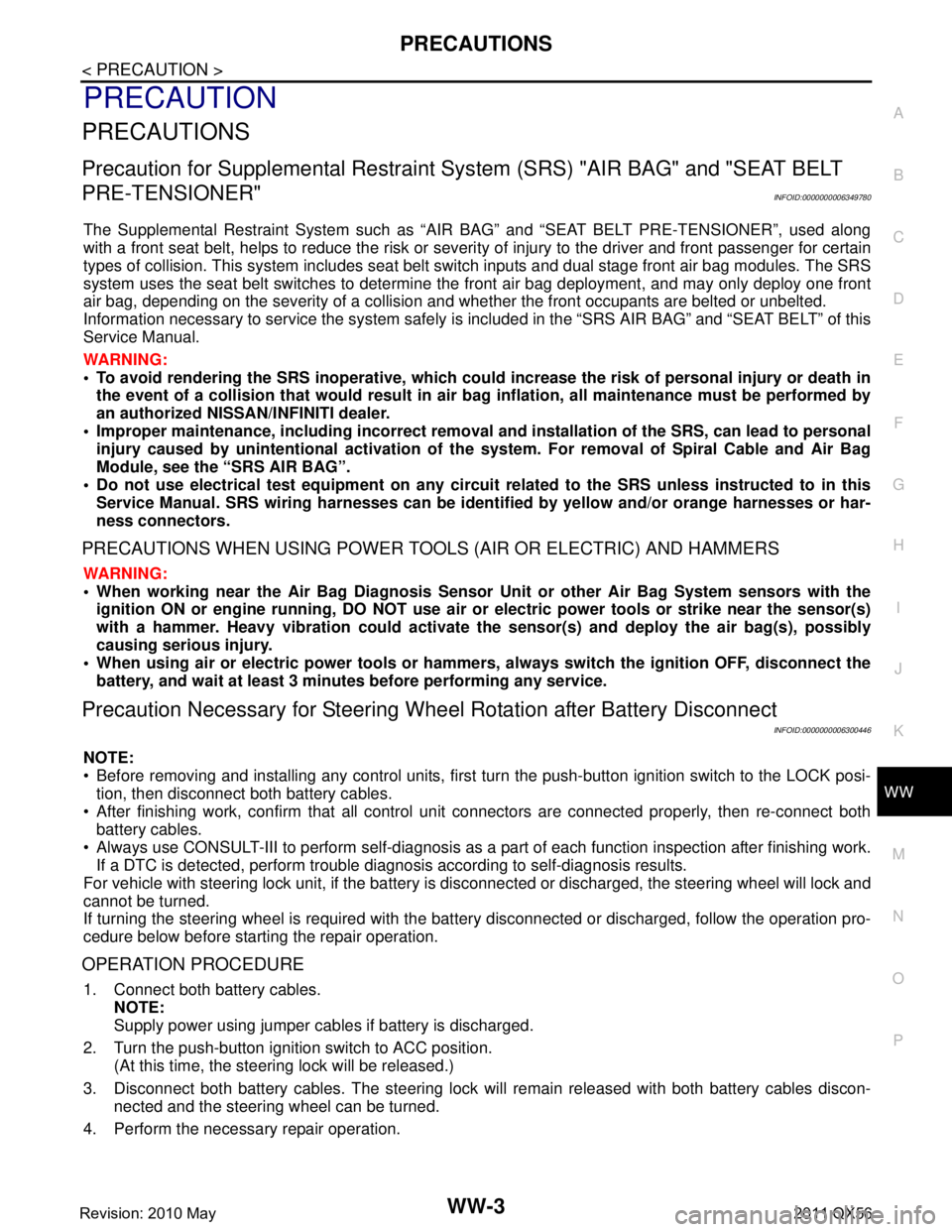
PRECAUTIONS
Precaution for Supplemental Restraint System (SRS) "AIR BAG" and "SEAT BELT
PRE-TENSIONER"
INFOID:0000000006349780
The Supplemental Restraint System such as “A IR BAG” and “SEAT BELT PRE-TENSIONER”, used along
with a front seat belt, helps to reduce the risk or severi ty of injury to the driver and front passenger for certain
types of collision. This system includes seat belt switch inputs and dual stage front air bag modules. The SRS
system uses the seat belt switches to determine the front air bag deployment, and may only deploy one front
air bag, depending on the severity of a collision and whether the front occupants are belted or unbelted.
Information necessary to service the system safely is included in the “SRS AIR BAG” and “SEAT BELT” of this
Service Manual.
WARNING:
• To avoid rendering the SRS inoper ative, which could increase the risk of personal injury or death in
the event of a collision that would result in air ba g inflation, all maintenance must be performed by
an authorized NISSAN/INFINITI dealer.
Improper maintenance, including in correct removal and installation of the SRS, can lead to personal
injury caused by unintentional act ivation of the system. For removal of Spiral Cable and Air Bag
Module, see the “SRS AIR BAG”.
Do not use electrical test equipm ent on any circuit related to the SRS unless instructed to in this
Service Manual. SRS wiring harnesses can be identi fied by yellow and/or orange harnesses or har-
ness connectors.
PRECAUTIONS WHEN USING POWER TOOLS (AIR OR ELECTRIC) AND HAMMERS
WARNING:
When working near the Air Bag Diagnosis Sensor Unit or other Air Bag System sensors with the
ignition ON or engine running, DO NOT use air or electric power tools or strike near the sensor(s)
with a hammer. Heavy vibration could activate the sensor(s) and deploy the air bag(s), possibly
causing serious injury.
When using air or electric power tools or hammers , always switch the ignition OFF, disconnect the
battery, and wait at least 3 minutes before performing any service.
Precaution Necessary for Steering Wh eel Rotation after Battery Disconnect
INFOID:0000000006300446
NOTE:
Before removing and installing any control units, first tu rn the push-button ignition switch to the LOCK posi-
tion, then disconnect both battery cables.
After finishing work, confirm that all control unit connectors are connected properly, then re-connect both
battery cables.
Always use CONSULT-III to perform self-diagnosis as a part of each function inspection after finishing work.
If a DTC is detected, perform trouble diagnos is according to self-diagnosis results.
For vehicle with steering lock unit, if the battery is disconnected or discharged, the steering wheel will lock and
cannot be turned.
If turning the steering wheel is required with the batte ry disconnected or discharged, follow the operation pro-
cedure below before starting the repair operation.
OPERATION PROCEDURE
1. Connect both battery cables. NOTE:
Supply power using jumper cables if battery is discharged.
2. Turn the push-button ignition switch to ACC position. (At this time, the steering lock will be released.)
3. Disconnect both battery cables. The steering lock wil l remain released with both battery cables discon-
nected and the steering wheel can be turned.
4. Perform the necessary repair operation.
Revision: 2010 May2011 QX56
Page 5534 of 5598

DIAGNOSIS SYSTEM (BCM)WW-15
< SYSTEM DESCRIPTION >
C
DE
F
G H
I
J
K
M A
B
WW
N
O P
WIPER
WIPER : CONSULT-III Function (BCM - WIPER)INFOID:0000000006300461
WORK SUPPORT
CONSULT screen item Indication/Unit Description
Vehicle Speed km/h Vehicle speed of the moment a particular DTC is detected
Odo/Trip Meter km Total mileage (Odometer value) of the moment a particular DTC is detected
Vehicle Condition SLEEP>LOCK
Power position status of
the moment a particular
DTC is detected While turning BCM status from low power consumption mode to
normal mode (Power supply position is “LOCK”)
SLEEP>OFF While turning BCM status from low power consumption mode to
normal mode (Power supply position is “OFF”.)
LOCK>ACC While turning power supply position from “LOCK” to “ACC”
ACC>ON While turning power supply position from “ACC” to “IGN”
RUN>ACC While turning power supply position
from “RUN” to “ACC” (Vehicle
is stopping and selector lever is except P position.)
CRANK>RUN While turning power su
pply position from “CRANKING” to “RUN”
(From cranking up the engine to run it)
RUN>URGENT While turning power su
pply position from “RUN“ to “ACC” (Emer-
gency stop operation)
ACC>OFF While turning power supply position from “ACC” to “OFF”
OFF>LOCK While turning power supply position from “OFF” to “LOCK”
OFF>ACC While turning power supply position from “OFF” to “ACC”
ON>CRANK While turning po wer supply position from “IGN” to “CRANKING”
OFF>SLEEP While turning BCM status from normal mode (Power supply posi-
tion is “OFF”.) to low power consumption mode
LOCK>SLEEP While turning BCM status from normal mode (Power supply posi-
tion is “LOCK”.) to low power consumption mode
LOCK Power supply position is “LOCK” (Ignition switch OFF with steer-
ing is locked.)
OFF Power supply position
is “OFF” (Ignition switch OFF with steering
is unlocked.)
ACC Power supply position is “ACC” (Ignition switch ACC)
ON Power supply position is “IGN” (Ignition switch ON with engine
stopped)
ENGINE RUN Power supply posi
tion is “RUN” (Ignition switch ON with engine
running)
CRANKING Power supply position is “CRANKING” (At engine cranking)
IGN Counter 0 - 39 The number of times that ignition switch is turned ON after DTC is detected
The number is 0 when a malfunction is detected now.
The number increases like 1
→ 2 → 3...38 → 39 after returning to the normal condition
whenever ignition switch OFF → ON.
The number is fixed to 39 until the self-diagnosis results are erased if it is over 39.
Service item Setting item Description
WIPER SPEED
SETTING*
1
On With vehicle speed
(Front wiper intermittent time linked with the vehicle speed and wip-
er intermittent dial position)
The setting of front wip-
er INT operation can be
changed
Off Without vehicle speed
(Front wiper intermittent time linked with the wiper intermittent dial
position)
Revision: 2010 May2011 QX56
Page 5535 of 5598

WW-16
< SYSTEM DESCRIPTION >
DIAGNOSIS SYSTEM (BCM)
*1:The item is indicated, but not operated
*2:Factory setting
DATA MONITOR
ACTIVE TEST
RAIN SEN WIP
FUNC SETOn*
2With rain sensor
(Front wiper intermittent time linked with the rain sensor, vehicle
speed, and AUTO dial position)
The setting of front wip-
er AUTO operation can
be changed
Off Without rain sensor
(Front wiper intermittent time linked with the vehicle speed and
AUTO dial position)
DROP WIPE
FUNC SET*
1
MODE1 Front wiper and rear wiper OFF The setting of drop wipe
operation can be
changed
MODE2*
2Front wiper ON and rear wiper OFF
MODE3 Front wiper OFF and rear wiper ON
MODE4 Front wiper and rear wiper ON
Service item Setting item Description
Monitor Item
[Unit] Description
PUSH SW
[Off/On] The switch status input from push-button ignition switch.
VEH SPEED 1
[km/h] Displays the value of the vehicle speed signal received from combination meter via CAN com-
munication.
FR WIPER HI
[Off/On]
Status of each switch judged by BCM using the combination switch reading function
FR WIPER LOW
[Off/On]
FR WASHER SW
[Off/On]
FR WIPER INT
[Off/On]
FR WIPER STOP
[Off/On]
Displays the status of the front wiper stop position signal received from IPDM E/R via CAN
communication.
INT VOLUME
[1 − 7] Status of each switch judged by BCM using the combination switch reading function
RR WIPER ON
[Off/On] Status of each switch judged by BCM using the combination switch reading function
RR WIPER INT
[Off/On]
RR WASHER SW
[Off/On]
RR WIPER STOP
[Off/On] Rear wiper motor (stop position) status input from the rear wiper motor
H/L WASH SW
[Off/On] NOTE:
This item is indicated, but not monitored
RAIN SENSOR
[OFF/LOW/HIGH/SPLASH/NG] Request signal from rain sensor detected by BCM is displayed
Revision: 2010 May2011 QX56
Page 5588 of 5598
FRONT WIPER BLADEWW-69
< REMOVAL AND INSTALLATION >
C
DE
F
G H
I
J
K
M A
B
WW
N
O P
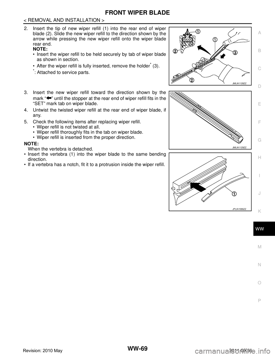
2. Insert the tip of new wiper refill (1) into the rear end of wiper blade (2). Slide the new wiper refill to the direction shown by the
arrow while pressing the new wiper refill onto the wiper blade
rear end.
NOTE:
Insert the wiper refill to be held securely by tab of wiper bladeas shown in section.
After the wiper refill is fully inserted, remove the holder
* (3).
*: Attached to service parts.
3. Insert the new wiper refill toward the direction shown by the mark “ ” until the stopper at the rear end of wiper refill fits in the
“SET” mark tab on wiper blade.
4. Untwist the twisted wiper refill at the rear end of wiper blade, if any.
5. Check the following items after replacing wiper refill. Wiper refill is not twisted at all.
Wiper refill thoroughly fits in the tab on wiper blade.
Wiper refill is inserted from the proper direction.
NOTE: When the vertebra is detached.
Insert the vertebra (1) into the wiper blade to the same bending direction.
If a vertebra has a notch, fit it to a protrusion inside the wiper refill.
JMLIA1128ZZ
JMLIA1129ZZ
JPLIA1586ZZ
Revision: 2010 May2011 QX56