door INFINITI QX56 2011 Factory Service Manual
[x] Cancel search | Manufacturer: INFINITI, Model Year: 2011, Model line: QX56, Model: INFINITI QX56 2011Pages: 5598, PDF Size: 94.53 MB
Page 3737 of 5598

MIR-32
< REMOVAL AND INSTALLATION >
OUTSIDE MIRROR
OUTSIDE MIRROR
Exploded ViewINFOID:0000000006257236
DOOR MIRROR ASSEMBLY
DOOR MIRROR ASSEMBLY : Removal and InstallationINFOID:0000000006257237
REMOVAL
1. Remove front door finisher and door mirror corner cover. Refer to INT-14, "Removal and Installation".
2. Disconnect door mirror assembly harness connector.
3. Remove door mirror mounting nuts, and then remove door mirror assembly.
1. Door mirror cover 2. Glas s mirror 3. Actuator assembly
4. Connector 5. Door mirror co ver 6. Side camera finisher
7. Around view camera 8. Side turn signal lamp 9. Housing
10. Bracket 11. Power fold unit 12. Base cover
13. Puddle lamp 14. Base : Clip
: Pawl
JMLIA1144ZZ
Revision: 2010 May2011 QX56
Page 3738 of 5598

OUTSIDE MIRRORMIR-33
< REMOVAL AND INSTALLATION >
C
DE
F
G H
I
J
K
M A
B
MIR
N
O P
INSTALLATION
Note the following item, and then install in the reverse order of removal.
CAUTION:
Perform camera image calibration (with side camera models). Refer to AV-112, "
Work Procedure".
DOOR MIRROR ASSEMBLY : Disassembly and AssemblyINFOID:0000000006257238
DISASSEMBLY
1. Remove door mirror assembly from front door panel. Refer to MIR-32, "DOOR MIRROR ASSEMBLY :
Removal and Installation".
2. Remove glass mirror. Refer to MIR-35, "
GLASS MIRROR : Removal and Installation".
3. Remove door mirror cover. Refer to MIR-36, "
DOOR MIRROR COVER : Removal and Installation".
4. Remove actuator. 1. Remove actuator (1) fixing screws (A).
2. Disconnect the harness connec tors behind the actuator.
NOTE:
Disconnect the harness connector (B) of automatic driving posi-
tion system (2) if equipped.
5. Remove side camera finisher assembly (1). 1. Remove side camera finisher fixing screw (A).
JMLIA0910ZZ
JMLIA0911ZZ
JMLIA0912ZZ
Revision: 2010 May2011 QX56
Page 3740 of 5598

OUTSIDE MIRRORMIR-35
< REMOVAL AND INSTALLATION >
C
DE
F
G H
I
J
K
M A
B
MIR
N
O P
9. Remove fixing screws (A), (B) and then remove power fold unit (2) from bracket (1).
ASSEMBLY
Assemble in the reverse order of disassembly.
GLASS MIRROR
GLASS MIRROR : Removal and InstallationINFOID:0000000006257239
REMOVAL
1. Remove door mirror assembly from front door. Refer to MIR-32, "DOOR MIRROR ASSEMBLY : Removal
and Installation".
2. Remove glass mirror. 1. Place the glass mirror upward.
2. Put a strip of protective tape (B) on housing assembly.
3. As shown in the figure, insert a small flat-bladed screwdriver (A) between glass mirror (1) and actuator (2). Push up both
pawls simultaneously to remove glass mirror lower half side.
NOTE:
Insert flat-bladed screwdriver into recesses, and push up
while rotating (twisting) to make work easier.
4. Remove terminals (A) of mi rror heater attachment from
glass mirror (1) if equipped.
3. Lightly lift up lower side of glass mirror, and detach both pawls of upper side as if pulling it out to disas- semble glass mirror from actuator.
NOTE:
Be careful not to allow grease on sealing agent in center of mirror or back side of glass mirror.
INSTALLATION
Note the following item, and then install in the reverse order n the reverse order of disassembly.
CAUTION:
After installation, visually check that pawls are securely engaged.
DOOR MIRROR COVER
JMLIA0924ZZ
JMLIA0158ZZ
JMLIA0908ZZ
Revision: 2010 May2011 QX56
Page 3741 of 5598

MIR-36
< REMOVAL AND INSTALLATION >
OUTSIDE MIRROR
DOOR MIRROR COVER : Re moval and Installation
INFOID:0000000006257240
CAUTION:
Never damage the mirror bodies.
REMOVAL
1. Remove the glass mirror. Refer to MIR-35, "GLASS MIRROR : Removal and Installation".
2. Remove the pawls (A), and disassemble door mirror cover from door mirror assembly.
INSTALLATION
Note the following item, and then install in the reverse order of removal.
CAUTION:
After installation, visually check that all the pawls are securely engaged.
SIDE CAMERA FINISHER ASSEMBLY
SIDE CAMERA FINISHER ASSEMBLY : Removal and InstallationINFOID:0000000006257241
Disassembly
1. Remove door mirror assembly from front door panel. Refer to MIR-32, "DOOR MIRROR ASSEMBLY :
Removal and Installation".
2. Remove glass mirror. Refer to MIR-35, "
GLASS MIRROR : Removal and Installation".
3. Remove door mirror cover. Refer to MIR-36, "
DOOR MIRROR COVER : Removal and Installation".
4. Remove side camera finisher (1) fixing screw (A).
5. Disconnect harness connector (B), and remove screws (C) and pawl (D) fixing the side camera finisher (1) to housing.
JMLIA1145ZZ
JMLIA0912ZZ
JMLIA0921ZZ
Revision: 2010 May2011 QX56
Page 3743 of 5598

MIR-38
< REMOVAL AND INSTALLATION >
DOOR MIRROR REMOTE CONTROL SWITCH
DOOR MIRROR REMOTE CONTROL SWITCH
Removal and InstallationINFOID:0000000006257242
REMOVAL
1. Remove the instrument lower panel LH. Refer to IP-14, "Removal and Installation".
2. Remove the screws (A).
3. Remove the door mirror remote control switch (1) from instrument lower panel LH (2).
INSTALLATION
Install in the reverse order of removal.
JMLIA0873ZZ
Revision: 2010 May2011 QX56
Page 3746 of 5598

MWI
MWI-3
C
DE
F
G H
I
J
K L
M B
A
O P
THE LOW WASHER FLUID WARNING CON-
TINUES DISPLAYING, or DOES NOT DIS-
PLAY .............................................................. ....
81
Description .......................................................... ....81
Diagnosis Procedure ...............................................81
THE DOOR OPEN WARNING CONTINUES
DISPLAYING, OR DOES NOT DISPLAY ..........
82
Description .......................................................... ....82
Diagnosis Procedure ...............................................82
THE AMBIENT TEMPERATURE DISPLAY IS
INCORRECT .......................................................
83
Description .......................................................... ....83
Diagnosis Procedure ...............................................83
NORMAL OPERATING CONDITION .................84
INFORMATION DISPLAY ..................................... ....84
INFORMATION DISPLAY : Description ..................84
REMOVAL AND INSTALLATION ...............85
COMBINATION METER ...................................85
Exploded View ..................................................... ....85
Removal and Installation .........................................85
Disassembly and Assembly .....................................85
TRIP RESET AND ILLUMINATION CON-
TROL SWITCH ..................................................
86
Exploded View .........................................................86
Removal and Installation .........................................86
TRIP COMPUTER SWITCH ..............................87
Exploded View .........................................................87
Removal and Installation .........................................87
CLOCK ..............................................................88
Exploded View .........................................................88
Removal and Installation .........................................88
Revision: 2010 May2011 QX56
Page 3750 of 5598

MWI
COMPONENT PARTSMWI-7
< SYSTEM DESCRIPTION >
C
DE
F
G H
I
J
K L
M B A
O P
METER SYSTEM : Com ponent DescriptionINFOID:0000000006221691
CLOCK
Unit Description
Combination meter Controls the following with the signals received from each unit via CAN communication and the sig-
nals from switches and sensors.
Speedometer
Tachometer
Engine coolant temperature gauge
Fuel gauge
Engine oil pressure gauge
Voltmeter
Warning lamps
Indicator lamps
Meter illumination control
Meter effect function
Information display
Trip computer switch Transmits the following signals to the combination meter.
Enter switch signal
Select switch signal
Trip reset and illumination con-
trol switch Transmits the following signals to the combination meter.
Trip reset switch signal
Illumination control switch signal (+)
Illumination control switch signal (
−)
ECM Transmits the following signals to the combination meter via CAN communication.
Engine speed signal
Engine coolant temperature signal
Engine status signal
Fuel consumption monitor signal
ABS actuator and electric unit
(control unit) Transmits the vehicle speed signal to the combination meter via CAN communication.
IPDM E/R Transmits the oil pressure switch signal to the BCM via CAN communication.
BCM Transmits the following signals to the combination meter via CAN communication.
Oil pressure switch signal
Position light request signal
Dimmer signal
Door switch signal
Meter ring illumination request signal
Starter relay status signal
TCM Transmits the shift position signal to the combination meter via CAN communication.
A/T shift selector Transmits the following signals to the combination meter.
Manual mode signal
Non-manual mode signal
Manual mode shift up signal
Manual mode shift down signal
Fuel level sensor unit Transmits the fuel level sensor signal to the combination meter.
Oil pressure switch Transmits the oil pressure switch signal to the IPDM E/R.
Ambient sensor Transmits the ambient sensor signal to the combination meter.
A/C auto amp. Transmits the A/C auto amp. connection recognition signal to the combination meter.
Parking brake switch Transmits the parking brake switch signal to the combination meter.
Washer level switch Transmits the washer level switch signal to the combination meter.
Revision: 2010 May2011 QX56
Page 3754 of 5598

MWI
SYSTEMMWI-11
< SYSTEM DESCRIPTION >
C
DE
F
G H
I
J
K L
M B A
O P
ARRANGEMENT OF COMBINATION METER
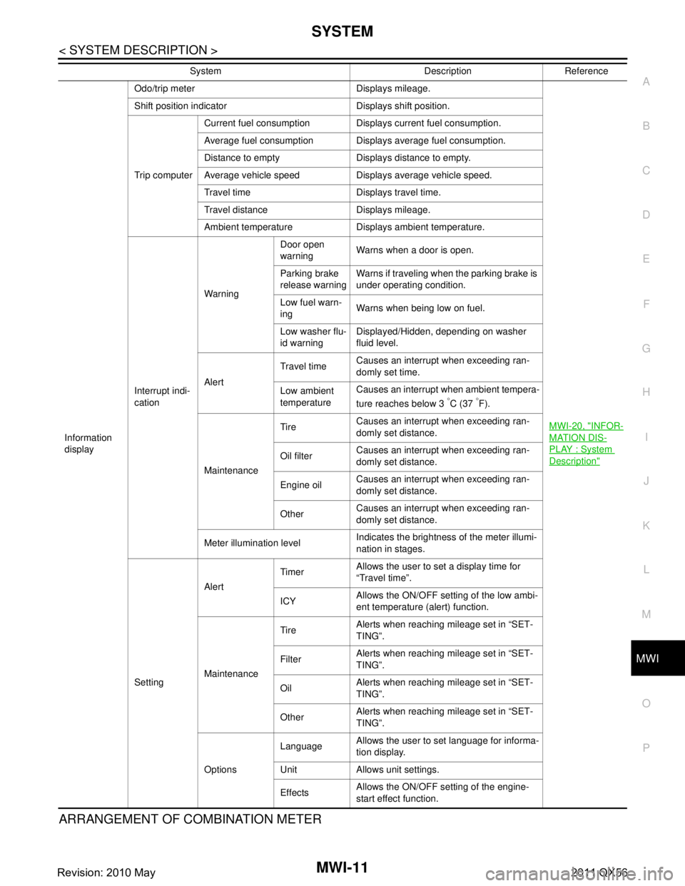
Information
display Odo/trip meter Displays mileage.
MWI-20, "
INFOR-
MATION DIS-
PLAY : System
Description"
Shift position indicator Displays shift position.
Trip computerCurrent fuel consumption Displays current fuel consumption.
Average fuel consumption Displays average fuel consumption.
Distance to empty Displays distance to empty.
Average vehicle speed Displays average vehicle speed.
Travel time Displays travel time.
Travel distance Displays mileage.
Ambient temperature Displays ambient temperature.
Interrupt indi-
cation Warning
Door open
warning
Warns when a door is open.
Parking brake
release warning Warns if traveling when the parking brake is
under operating condition.
Low fuel warn-
ing Warns when being low on fuel.
Low washer flu-
id warning Displayed/Hidden, depending on washer
fluid level.
Alert Travel time
Causes an interrupt when exceeding ran-
domly set time.
Low ambient
temperature Causes an interrupt when ambient tempera-
ture reaches below 3
°C (37 °F).
Maintenance Tire
Causes an interrupt when exceeding ran-
domly set distance.
Oil filter Causes an interrupt when exceeding ran-
domly set distance.
Engine oil Causes an interrupt when exceeding ran-
domly set distance.
Other Causes an interrupt when exceeding ran-
domly set distance.
Meter illumination level Indicates the brightness of the meter illumi-
nation in stages.
Setting Alert
Timer
Allows the user to set a display time for
“Travel time”.
ICY Allows the ON/OFF setting of the low ambi-
ent temperature (alert) function.
Maintenance Tire
Alerts when reaching mileage set in “SET-
TING”.
Filter Alerts when reaching mileage set in “SET-
TING”.
Oil Alerts when reaching mileage set in “SET-
TING”.
Other Alerts when reaching mileage set in “SET-
TING”.
Options Language
Allows the user to set language for informa-
tion display.
Unit Allows unit settings.
Effects Allows the ON/OFF setting of the engine-
start effect function.
System Description Reference
Revision: 2010 May2011 QX56
Page 3755 of 5598

MWI-12
< SYSTEM DESCRIPTION >
SYSTEM
METER SYSTEM : Fail-Safe
INFOID:0000000006221695
FA I L - S A F E
The combination meter activates the fail-safe contro l if CAN communication with each unit is malfunctioning.
A. With ASCD models B. With ICC models C. For U.S.A.
D. For Canada
JSNIA3234ZZ
Function Specifications
Speedometer
Reset to zero by suspending communication.
Tachometer
Engine coolant temperature gauge
Engine oil pressure gauge
Illumination control When suspending communication, changes to nighttime mode.
Information display Odo/trip meter An indicated value is maintained at communications blackout.
Shift position indicator The display turns OFF by suspending communication.
Door open warning The display turns OFF by suspending communication.
Buzzer The buzzer turns OFF by suspending communication.
Revision: 2010 May2011 QX56
Page 3759 of 5598

MWI-16
< SYSTEM DESCRIPTION >
SYSTEM
OIL PRESSURE WARNING LAMP : System Description
INFOID:0000000006221709
IPDM E/R reads the ON/OFF signals fr om the oil pressure switch and transmits the oil pressure switch sig-
nal to the combination meter via BCM with the CAN communication.
The combination meter turns the oil pressure warning lamp ON (at the time of a reduction in hydraulic pres-
sure)/OFF (except at the time of a reduction in hydraulic pressure) according to the oil pressure switch signal
received via CAN communication.
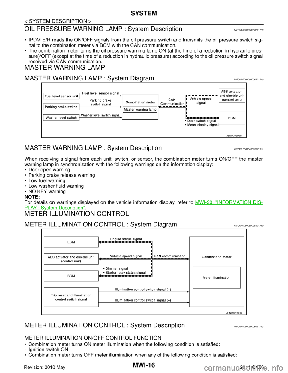
MASTER WARNING LAMP
MASTER WARNING LAMP : System DiagramINFOID:0000000006221710
MASTER WARNING LAMP : System DescriptionINFOID:0000000006221711
When receiving a signal from each unit, switch, or s ensor, the combination meter turns ON/OFF the master
warning lamp in synchronization with the following warnings on the information display:
Door open warning
Parking brake release warning
Low fuel warning
Low washer fluid warning
NO KEY warning
NOTE:
For details on warnings displayed on the vehicle information display, refer to MWI-20, "
INFORMATION DIS-
PLAY : System Description".
METER ILLUMINATION CONTROL
METER ILLUMINATION CONTROL : System DiagramINFOID:0000000006221712
METER ILLUMINATION CONTRO L : System DescriptionINFOID:0000000006221713
METER ILLUMINATION ON/OFF CONTROL FUNCTION
Combination meter turns ON meter illumination when the following condition is satisfied:
- Ignition switch ON
Combination meter turns OFF meter illumination when any of the following condition is satisfied:
JSNIA3098GB
JSNIA3235GB
Revision: 2010 May2011 QX56