check engine INFINITI QX56 2011 Factory Service Manual
[x] Cancel search | Manufacturer: INFINITI, Model Year: 2011, Model line: QX56, Model: INFINITI QX56 2011Pages: 5598, PDF Size: 94.53 MB
Page 2801 of 5598
![INFINITI QX56 2011 Factory Service Manual
HEADLAMP LEVELIZER CIRCUITEXL-91
< DTC/CIRCUIT DIAGNOSIS > [XENON TYPE]
C
D
E
F
G H
I
J
K
M A
B
EXL
N
O P
HEADLAMP LEVELIZER CIRCUIT
Component Function CheckINFOID:0000000006213960
1.CHECK AIMING MOT INFINITI QX56 2011 Factory Service Manual
HEADLAMP LEVELIZER CIRCUITEXL-91
< DTC/CIRCUIT DIAGNOSIS > [XENON TYPE]
C
D
E
F
G H
I
J
K
M A
B
EXL
N
O P
HEADLAMP LEVELIZER CIRCUIT
Component Function CheckINFOID:0000000006213960
1.CHECK AIMING MOT](/img/42/57033/w960_57033-2800.png)
HEADLAMP LEVELIZER CIRCUITEXL-91
< DTC/CIRCUIT DIAGNOSIS > [XENON TYPE]
C
D
E
F
G H
I
J
K
M A
B
EXL
N
O P
HEADLAMP LEVELIZER CIRCUIT
Component Function CheckINFOID:0000000006213960
1.CHECK AIMING MOTOR OPERATION
CONSULT-III ACTIVE TEST
1. Start the engine.
2. Turn the lighting switch 2ND.
3. Select “LEVELIZER TEST” of ADAP TIVE LIGHT active test item.
4. With operating the test item, check the operation.
Is the operation normal?
YES >> Headlamp levelizer circuit is normal.
NO >> Refer to EXL-91, "
Diagnosis Procedure".
Diagnosis ProcedureINFOID:0000000006213961
1.CHECK AIMING MOTOR DRIVE SIGNAL OUTPUT
CONSULT-III ACTIVE TEST
1. Start the engine.
2. Turn light switch 2ND.
3. Select “LEVELIZER TEST” of ADAP TIVE LIGHT active test item.
4. With operating the test item, check voltage between AFS control unit harness connector and ground.
Is the inspection result normal?
YES >> GO TO 2.
NO >> GO TO 3.
2.CHECK AIMING MOTOR DRIVE SIGNAL OPEN CIRCUIT
1. Turn ignition switch OFF.
2. Disconnect AFS control unit connector and headlamp aiming motor connector.
3. Check continuity between AFS control unit har ness connector and head lamp aiming motor harness con-
nector.
Is the inspection result normal?
YES >> Replace front combination lamp.
NO >> Repair or replace harness.
Te s t i t e m Optical axis
LEVELIZER TEST
Origin Standard positonPeak Lowest position
(+) (− ) Test item Voltag e
(Approx.)
AFS control unit
Connector Terminal
RH M13519
Ground LEVELIZER TEST Origin 7.5 V
Peak 7.3 V
LH 40 Origin 7.5 V
Peak 7.3 V
AFS control unit Headlamp aiming motor
Continuity
Connector Terminal Connector Terminal
RH M13519 E121
1 Existed
LH 40 E120
Revision: 2010 May2011 QX56
Page 2831 of 5598
![INFINITI QX56 2011 Factory Service Manual
HEADLAMP AIMING ADJUSTMENTEXL-121
< PERIODIC MAINTENANCE > [XENON TYPE]
C
D
E
F
G H
I
J
K
M A
B
EXL
N
O P
PERIODIC MAINTENANCE
HEADLAMP AIMING ADJUSTMENT
descriptionINFOID:0000000006213990
preparatio INFINITI QX56 2011 Factory Service Manual
HEADLAMP AIMING ADJUSTMENTEXL-121
< PERIODIC MAINTENANCE > [XENON TYPE]
C
D
E
F
G H
I
J
K
M A
B
EXL
N
O P
PERIODIC MAINTENANCE
HEADLAMP AIMING ADJUSTMENT
descriptionINFOID:0000000006213990
preparatio](/img/42/57033/w960_57033-2830.png)
HEADLAMP AIMING ADJUSTMENTEXL-121
< PERIODIC MAINTENANCE > [XENON TYPE]
C
D
E
F
G H
I
J
K
M A
B
EXL
N
O P
PERIODIC MAINTENANCE
HEADLAMP AIMING ADJUSTMENT
descriptionINFOID:0000000006213990
preparation before adjusting
NOTE:
for details, refer to the regulations in your own country.
perform aiming if the vehicle front body has been repaired and/or the headlamp assembly has been
replaced.
before performing aiming adjustment, check the following. adjust the tire pressure to the specification.
fill with fuel, engine coolant and each oil.
maintain the unloaded vehicle condition. (remove luggage from the passenger compartment and the lug- gage room.)
NOTE:
do not remove the temporary tire, jack and on-vehicle tool.
wipe out dirt on the headlamp.
CAUTION:
never use organic solvent (thinner, gasoline etc.)
ride alone on the driver seat.
aiming adjustment screw
JMLIA1319ZZ
A. Headlamp RH HI /LO (UP/DOWN)
adjustment screw B. Headlamp LH HI/LO (UP/DOWN)
adjustment screw
: Vehicle center
Revision: 2010 May2011 QX56
Page 2833 of 5598
![INFINITI QX56 2011 Factory Service Manual
FRONT FOG LAMP AIMING ADJUSTMENTEXL-123
< PERIODIC MAINTENANCE > [XENON TYPE]
C
D
E
F
G H
I
J
K
M A
B
EXL
N
O P
FRONT FOG LAMP AI MING ADJUSTMENT
DescriptionINFOID:0000000006213992
PREPARATION BEFORE INFINITI QX56 2011 Factory Service Manual
FRONT FOG LAMP AIMING ADJUSTMENTEXL-123
< PERIODIC MAINTENANCE > [XENON TYPE]
C
D
E
F
G H
I
J
K
M A
B
EXL
N
O P
FRONT FOG LAMP AI MING ADJUSTMENT
DescriptionINFOID:0000000006213992
PREPARATION BEFORE](/img/42/57033/w960_57033-2832.png)
FRONT FOG LAMP AIMING ADJUSTMENTEXL-123
< PERIODIC MAINTENANCE > [XENON TYPE]
C
D
E
F
G H
I
J
K
M A
B
EXL
N
O P
FRONT FOG LAMP AI MING ADJUSTMENT
DescriptionINFOID:0000000006213992
PREPARATION BEFORE ADJUSTING
NOTE:
For details, refer to the regulations in your own country.
Perform aiming if the vehicle front body has been repaired and/or the headlamp assembly has been
replaced.
Before performing aiming adjustm ent, check the following. Adjust the tire pressure to the specification.
Fill with fuel, engine coolant and each oil.
Maintain the unloaded vehicle condition. (Remove luggage from the passenger compartment and the trunk
room.)
NOTE:
Do not remove the temporary tire, jack and on-vehicle tool.
Wipe out dirt on the headlamp. CAUTION:
Never use organic solvent (thinner, gasoline etc.)
Ride alone on the driver seat.
AIMING ADJUSTMENT SCREW
Turn the aiming adjusting screw for adjustment.
For the position and direction of the adjusting screw, refer to the figure.
NOTE:
A screwdriver or hexagonal wrench [6 mm (0.24 in)] can be used
for adjustment.
Aiming Adjustment ProcedureINFOID:0000000006213993
1. Place the screen. NOTE:
Stop the vehicle facing the wall.
Place the board on a plain road vertically.
2. Face the vehicle with the screen. Maintain 10 m (32.8 ft) between the front fog lamp center and the
screen.
3. Start the engine. Turn the front fog lamp ON. NOTE:
Shut off the headlamp light with the board to pr event from illuminating the adjustment screen.
CAUTION:
Never cover the lens surface with a tape etc. The lens is made of resin.
4. Adjust the cutoff line height (A) with the aiming adjus tment screw so that the distance (X) between the hor-
izontal center line of front fog lamp (H) and (A) becomes 200 mm (7.87 in).
A: UP
B: DOWN
JPLIA0915ZZ
Revision: 2010 May2011 QX56
Page 2862 of 5598

SQUEAK AND RATTLE TROUBLE DIAGNOSESEXT-7
< SYMPTOM DIAGNOSIS >
C
DE
F
G H
I
J
L
M A
B
EXT
N
O P
If possible, drive the vehicle with the customer until the noise is duplicated. Note any additional information on
the Diagnostic Worksheet regarding the conditions or lo cation of the noise. This information can be used to
duplicate the same conditions when the repair is reconfirmed.
If the noise can be duplicated easily during the test drive, to help identify the source of the noise, try to dupli-
cate the noise with the vehicle stopped by doing one or all of the following items:
1) Close a door.
2) Tap or push/pull around the area where the noise appears to be coming from.
3) Rev the engine.
4) Use a floor jack to recreate vehicle “twist”.
5) At idle, apply engine load (electrical load, half-cl utch on M/T models, drive position on A/T models).
6) Raise the vehicle on a hoist and hit a tire with a rubber hammer.
Drive the vehicle and attempt to duplicate the conditions the customer states exist when the noise occurs.
If it is difficult to duplicate the noise, drive the vehicle slowly on an undulating or rough road to stress the
vehicle body.
CHECK RELATED SERVICE BULLETINS
After verifying the customer concern or symptom, che ck ASIST for Technical Service Bulletins (TSBs) related
to the concern or symptom.
If a TSB relates to the symptom, follow the procedure to repair the noise.
LOCATE THE NOISE AND IDENTIFY THE ROOT CAUSE
1. Narrow down the noise to a general area. To help pinpoint the source of the noise, use a listening tool
(Chassis ear: J-39570, engine ear, and mechanics stethoscope).
2. Narrow down the noise to a more specific area and identify the cause of the noise by:
Removing the component(s) in the area that is / are suspected to be the cause of the noise.
Do not use too much force when removing clips and fasteners, otherwise clips and fasteners can be broken
or lost during the repair, resulting in the creation of new noise.
Tapping or pushing/pulling the component(s) that is / are suspected to be the cause of the noise.
Do not tap or push/pull the component(s) with excessive force, otherwise the noise is eliminated only tempo-
rarily.
Feeling for a vibration by hand by touching the component(s ) that is / are suspected to be the cause of the
noise.
Placing a piece of paper between components that are suspected to be the cause of the noise.
Looking for loose components and contact marks. Refer to EXT-8, "
Inspection Procedure".
REPAIR THE CAUSE
If the cause is a loose component, tighten the component securely.
If the cause is insufficient clearance between components:
- Separate components by repositioning or loosening and retightening the components, if possible.
- Insulate components with a suitable insulator such as urethane pads, foam blocks, felt cloth tape, or ure-
thane tape. A NISSAN Squeak and Rattle Kit (J-43980) is available through the authorized NISSAN Parts
Department.
CAUTION:
Never use excessive force as many components are constructed of plastic and may be damaged.
NOTE:
Always check with the Parts Department for the latest parts information.
The following materials are contained in the NISSA N Squeak and Rattle Kit (J-43980). Each item can be
ordered separately as needed.
URETHANE PADS [1.5 mm (0.059 in) thick]
Insulates connectors, harness, etc.
76268-9E005: 100 ×135 mm (3.937 ×5.315 in)
76884-71L01: 60 ×85 mm (2.362 ×3.346 in)
76884-71L02: 15 ×25 mm (0.591 ×0.984 in)
INSULATOR (Foam blocks)
Insulates components from contact. Can be used to fill space behind a panel.
73982-9E000: 45 mm (1.772 in) thick, 50 ×50 mm (1.969 ×1.969 in)
73982-50Y00: 10 mm (0.394 in) thick, 50 ×50 mm (1.969 ×1.969 in)
INSULATOR (Light foam block)
80845-71L00: 30 mm (1.181 in) thick, 30 ×50 mm (1.181 ×1.969in)
FELT CLOTHTAPE
Revision: 2010 May2011 QX56
Page 2931 of 5598
FL-2
< PRECAUTION >
PRECAUTIONS
PRECAUTION
PRECAUTIONS
General PrecautionsINFOID:0000000006289679
WARNING:
When replacing fuel line parts, be sure to observe the following.
• Put a “CAUTION: FLAMMABLE” sign in the workshop.
Be sure to work in a well ventilate d area and furnish workshop with a CO
2 fire extinguisher.
Never smoke while servicing fuel system. Keep open flames and sparks away from the work area.
CAUTION:
Use gasoline required by the regulations for octane number. Refer to GI-31, "
Fuel".
Before removing fuel line parts, perform out the following procedures:
- Put drained fuel in an explosi on-proof container and put the lid on securely. Keep the container in
safe area.
- Release fuel pressure from the fuel lines. Refer to EC-153, "
Work Procedure".
- Disconnect the battery cable from the negative terminal.
Always replace O-rings with new ones.
Never kink or twist tubes when they are being installed.
Never tighten hose clamps excessi vely to avoid damaging hoses.
After installing tubes, check there is no fuel leakage at connections in the following steps.
- Apply fuel pressure to fuel lin es with turning ignition switch “O N” (with engine stopped). Then check
for fuel leakage at connections.
- Start engine and rev it up and check for fuel leakage at connections.
Use only a genuine NISSAN fuel filler cap as a replacemen t. If an incorrect fuel filler cap is used, the
“MIL” may come on.
For servicing “Evaporative Emission System” parts.
Refer to EC-16, "
Component Parts Location".
Revision: 2010 May2011 QX56
Page 2933 of 5598
FL-4
< PERIODIC MAINTENANCE >
FUEL SYSTEM
PERIODIC MAINTENANCE
FUEL SYSTEM
InspectionINFOID:0000000006289682
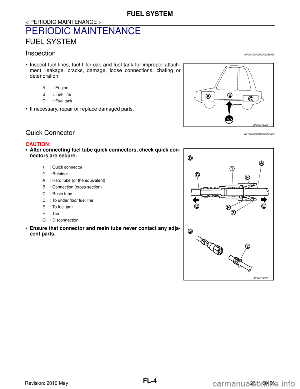
• Inspect fuel lines, fuel filler cap and fuel tank for improper attach-ment, leakage, cracks, damage, loose connections, chafing or
deterioration.
If necessary, repair or replace damaged parts.
Quick ConnectorINFOID:0000000006289683
CAUTION:
After connecting fuel tube quick connectors, check quick con-
nectors are secure.
Ensure that connector and resi n tube never contact any adja-
cent parts.
A : Engine
B : Fuel line
C: Fuel tank
JPBIA0129ZZ
1 : Quick connector
2: Retainer
A : Hard tube (or the equivalent)
B : Connection (cross-section)
C : Resin tube
D : To under floor fuel line
E : To fuel tank
F: Tab
G : Disconnection
JPBIA0130ZZ
Revision: 2010 May2011 QX56
Page 2936 of 5598
FUEL LEVEL SENSOR UNIT, FUEL FILTER AND FUEL PUMP ASSEMBLY
FL-7
< REMOVAL AND INSTALLATION >
C
D E
F
G H
I
J
K L
M A
FL
NP
O
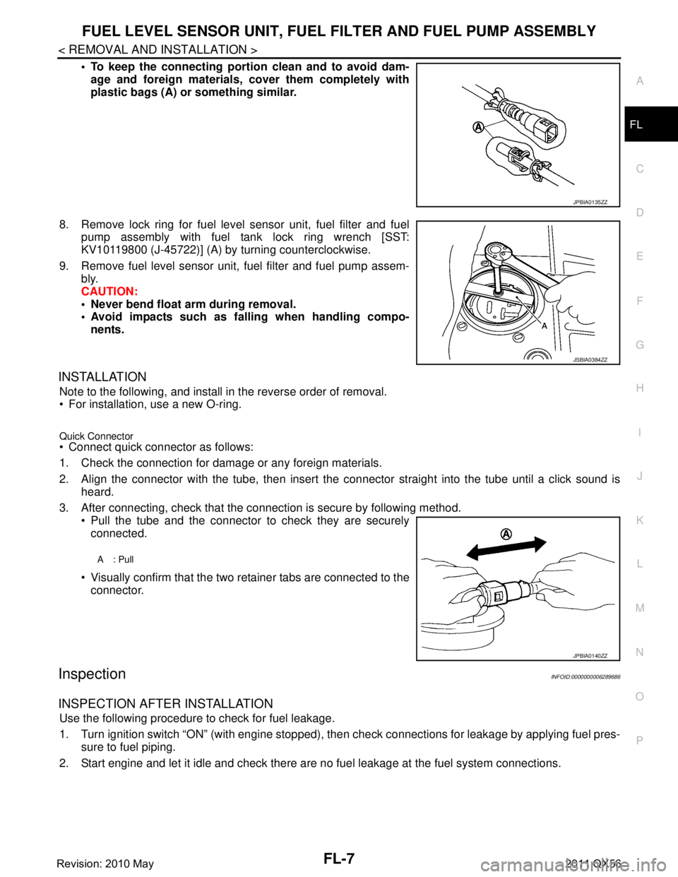
To keep the connecting portio
n clean and to avoid dam-
age and foreign materials, cover them completely with
plastic bags (A) or something similar.
8. Remove lock ring for fuel level sensor unit, fuel filter and fuel pump assembly with fuel tank lock ring wrench [SST:
KV10119800 (J-45722)] (A) by turning counterclockwise.
9. Remove fuel level sensor unit, fuel filter and fuel pump assem- bly.
CAUTION:
Never bend float arm during removal.
Avoid impacts such as fa lling when handling compo-
nents.
INSTALLATION
Note to the following, and install in the reverse order of removal.
For installation, use a new O-ring.
Quick Connector Connect quick connector as follows:
1. Check the connection for damage or any foreign materials.
2. Align the connector with the tube, then insert the connector straight into the tube until a click sound is
heard.
3. After connecting, check that the connection is secure by following method. Pull the tube and the connector to check they are securely
connected.
Visually confirm that the two retainer tabs are connected to the connector.
InspectionINFOID:0000000006289686
INSPECTION AFTER INSTALLATION
Use the following procedure to check for fuel leakage.
1. Turn ignition switch “ON” (with engine stopped), then check connections for leakage by applying fuel pres-
sure to fuel piping.
2. Start engine and let it idle and check there are no fuel leakage at the fuel system connections.
JPBIA0135ZZ
JSBIA0384ZZ
A: Pull
JPBIA0140ZZ
Revision: 2010 May2011 QX56
Page 2938 of 5598

FUEL TANKFL-9
< REMOVAL AND INSTALLATION >
C
DE
F
G H
I
J
K L
M A
FL
NP
O
3. Remove LH rear wheel and tire.
4. Disconnect fuel filler hose, vent hose and EVAP hose at fuel tank side.
5. Remove fuel tank protector.
6. Remove the fuel tank mounting band bolts while supporting the
fuel tank with a suitable lift jack.
CAUTION:
Support the position that fu el tank mounting bands never
engage.
7. Supporting with hands, descend suitable jack carefully, and remove fuel tank. CAUTION:
Check that all connection po ints have been disconnected.
Confirm there is no interference with vehicle.
InspectionINFOID:0000000006289689
INSPECTION AFTER INSTALLATION
Use the following procedure to check for fuel leakage.
1. Turn ignition switch “ON” (with engine stopped), and check connections for leakage by applying fuel pres-
sure to fuel piping.
2. Start engine and rev it up and check there are no f uel leakage at the fuel system tube and hose connec-
tions.
After removing/installing rear suspension assembly, check to adjust wheel alignment. Refer to RSU-6,
"Inspection".
LBIA0413E
Revision: 2010 May2011 QX56
Page 2945 of 5598
PRECAUTIONSFSU-3
< PRECAUTION >
C
DF
G H
I
J
K L
M A
B
FSU
N
O P
5. When the repair work is completed, re-connect both battery cables. With the brake pedal released, turn
the push-button ignition switch from ACC position to ON position, then to LOCK position. (The steering
wheel will lock when the push-button ignition switch is turned to LOCK position.)
6. Perform self-diagnosis check of a ll control units using CONSULT-III.
Precaution for Procedure without Cowl Top CoverINFOID:0000000006271994
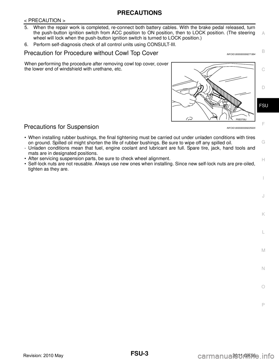
When performing the procedure after removing cowl top cover, cover
the lower end of windshield with urethane, etc.
Precautions for SuspensionINFOID:0000000006225635
When installing rubber bushings, the final tightening mu st be carried out under unladen conditions with tires
on ground. Spilled oil might shorten the life of rubb er bushings. Be sure to wipe off any spilled oil.
- Unladen conditions mean that fuel, engine coolant and l ubricant are full. Spare tire, jack, hand tools and
mats are in designated positions.
After servicing suspension parts, be sure to check wheel alignment.
Self-lock nuts are not reusable. Always use new ones w hen installing. Since new self-lock nuts are pre-oiled,
tighten as they are.
PIIB3706J
Revision: 2010 May2011 QX56
Page 2949 of 5598
WHEEL ALIGNMENTFSU-7
< PERIODIC MAINTENANCE >
C
DF
G H
I
J
K L
M A
B
FSU
N
O P
WHEEL ALIGNMENT
InspectionINFOID:0000000006225640
DESCRIPTION
Measure wheel alignment under unladen conditions.
NOTE:
“Unladen conditions” means that fuel, engine coolant, and lubricant are full. Spare tire, jack, hand tools and
mats are in designated positions.
PRELIMINARY CHECK
Check the following:
Tires for improper air pressure and wear
Road wheels for runout: Refer to WT-64, "
Inspection".
Wheel bearing axial end play: Refer to FA X - 7 , "
Inspection" (2WD), FAX-16, "Inspection" (4WD).
Lower link and upper link ball joint axial end play: Refer to FSU-15, "
Inspection" and FSU-18, "Inspection".
Shock absorber operation.
Each mounting part of axle and suspension for looseness and deformation
Lower link for cracks, deformation and other damage
Vehicle height (posture)
GENERAL INFORMATION AND RECOMMENDATIONS
A four-wheel thrust alignment should be performed.
- This type of alignment is recomm ended for any NISSAN/INFINITI vehicle.
- The four-wheel “thrust” process helps ensure that t he vehicle is properly aligned and the steering wheel is
centered.
- The alignment rack itself should be capable of accepting any NISSAN/INFINITI vehicle.
- The rack should be checked to ensure that it is level.
Make sure the machine is properly calibrated.
- Your alignment equipment should be regularly ca librated in order to give correct information.
- Check with the manufacturer of your specific equi pment for their recommended Service/Calibration Sched-
ule.
ALIGNMENT PROCESS
IMPORTANT:
Use only the alignment specificati ons listed in this Service Manual.
When displaying the alignment settings, many alignment machines use “indicators”: (Green/red, plus or
minus, Go/No Go). Never use these indicators.
- The alignment specifications programmed into your machine that operate these indicators may not be cor-
rect.
- This may result in an ERROR.
Some newer alignment machines are equipped with an optional “Rolling Compensation” method to “com-
pensate” the sensors (alignment targets or head units). Never use this “Rolling Compensation” method.
- Use the “Jacking Compensation Method”. After installi ng the alignment targets or head units, raise the vehi-
cle and rotate the wheels 1/2 turn both ways.
- See Instructions in the alignment machine you're using for more information on this.
AdjustmentINFOID:0000000006225641
CAMBER, CASTER
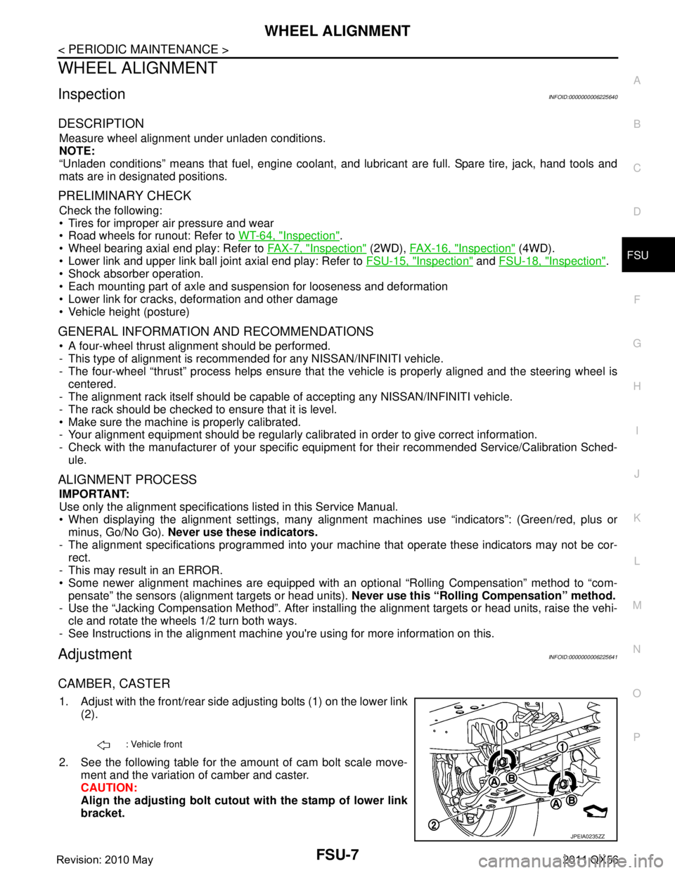
1. Adjust with the front/rear side adjusting bolts (1) on the lower link
(2).
2. See the following table for the amount of cam bolt scale move- ment and the variation of camber and caster.
CAUTION:
Align the adjusting bolt cutout with the stamp of lower link
bracket.
: Vehicle front
JPEIA0235ZZ
Revision: 2010 May2011 QX56