maintenance INFINITI QX56 2011 Factory Repair Manual
[x] Cancel search | Manufacturer: INFINITI, Model Year: 2011, Model line: QX56, Model: INFINITI QX56 2011Pages: 5598, PDF Size: 94.53 MB
Page 2582 of 5598

EM-20
< PERIODIC MAINTENANCE >
DRIVE BELTS
PERIODIC MAINTENANCE
DRIVE BELTS
Exploded ViewINFOID:0000000006289524
CheckingINFOID:0000000006289525
WARNING:
Be sure to perform the these steps when engine is stopped.
Check that the indicator (C) (notch on fixed side) of each auto-tensioner is within the possible use range (A).
NOTE:
Check the each auto-tensioners indication when the engine is cold.
When new drive belts is installed, the indicator (notch on fixed side) should be within the range (B) in the\
figure.
Visually check all drive belts for wear, damage or cracks.
If the indicator (notch on fixed side) is out of the possible use range or drive belts are damaged, replace drive
belts.
Tension AdjustmentINFOID:0000000006289526
Refer to EM-132, "Drive Belts".
Removal and InstallationINFOID:0000000006289527
REMOVAL
1. Move reservoir tank to the position without the hindrance for work. Refer to CO-13, "Exploded View".
1. Drive belt 2. Power steering oil pump pulley 3. Alternator pulley
4. Crankshaft pulley 5. A/C compressor 6. Idler pulley
7. Cooling fan pulley 8. Water pump pulley 9. Drive belt auto-tensioner
A. Possible use range B. Range when new drive belt is in-
stalledC. Indicator
D. View D
JPBIA3264ZZ
Revision: 2010 May2011 QX56
Page 2583 of 5598

DRIVE BELTSEM-21
< PERIODIC MAINTENANCE >
C
DE
F
G H
I
J
K L
M A
EM
NP
O
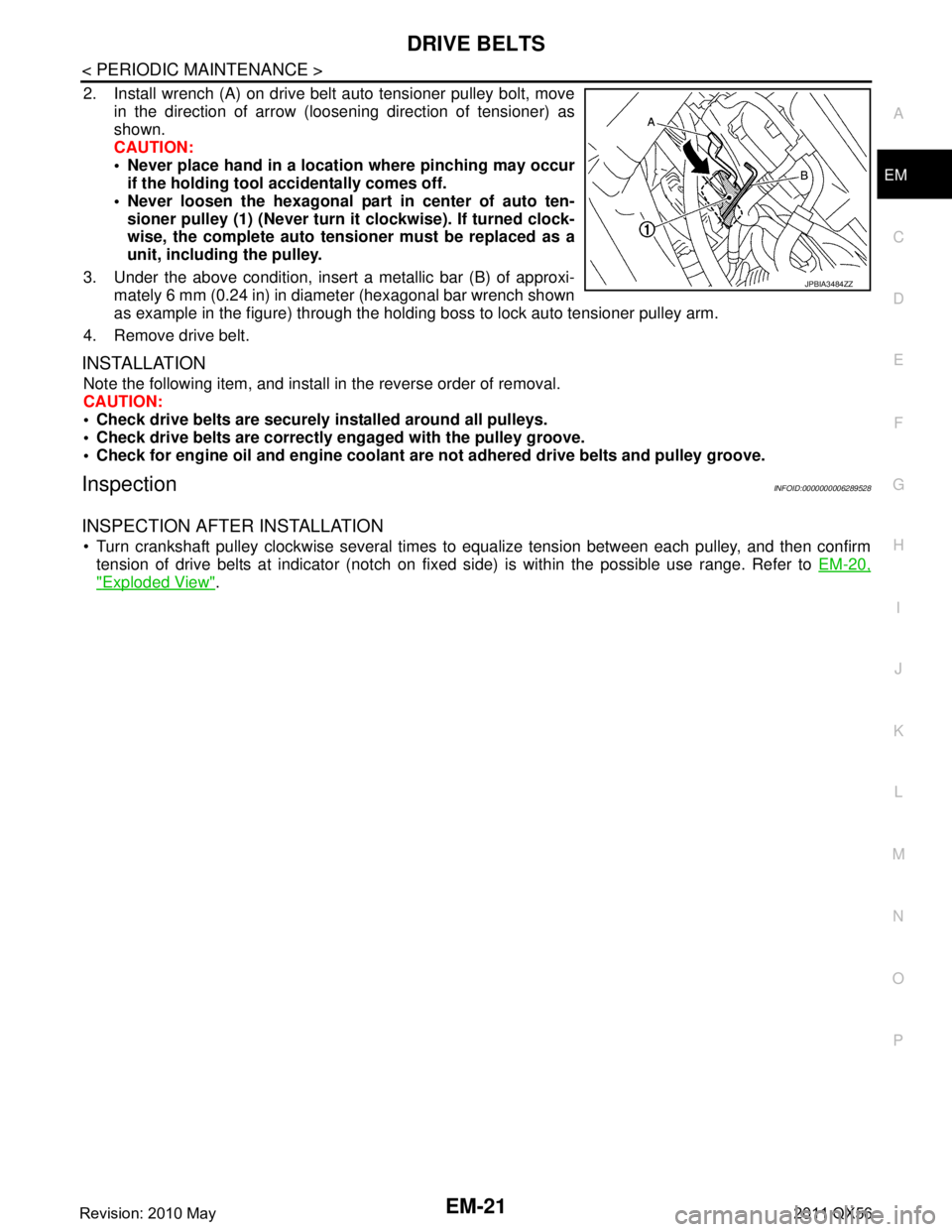
2. Install wrench (A) on drive belt auto tensioner pulley bolt, move
in the direction of arrow (loosening direction of tensioner) as
shown.
CAUTION:
Never place hand in a location where pinching may occurif the holding tool accidentally comes off.
Never loosen the hexagonal part in center of auto ten- sioner pulley (1) (Never turn it clockwise). If turned clock-
wise, the complete auto tensioner must be replaced as a
unit, including the pulley.
3. Under the above condition, insert a metallic bar (B) of approxi- mately 6 mm (0.24 in) in diameter (hexagonal bar wrench shown
as example in the figure) through the holding boss to lock auto tensioner pulley arm.
4. Remove drive belt.
INSTALLATION
Note the following item, and install in the reverse order of removal.
CAUTION:
Check drive belts are securely installed around all pulleys.
Check drive belts are correctly engaged with the pulley groove.
Check for engine oil and engine coolant ar e not adhered drive belts and pulley groove.
InspectionINFOID:0000000006289528
INSPECTION AFTER INSTALLATION
Turn crankshaft pulley clockwise several times to equalize tension between each pulley, and then confirm
tension of drive belts at indicator (notch on fixed side) is within the possible use range. Refer to EM-20,
"Exploded View".
JPBIA3484ZZ
Revision: 2010 May2011 QX56
Page 2584 of 5598

EM-22
< PERIODIC MAINTENANCE >
AIR CLEANER FILTER
AIR CLEANER FILTER
Exploded ViewINFOID:0000000006289529
Removal and InstallationINFOID:0000000006289530
REMOVAL
NOTE:
The viscous paper type filter does not need cleaning between replacement intervals.
Replace the air filter as necessary for periodic maintenance. Refer to MA-6, "
Introduction of Periodic Mainte-
nance".
1. Unhook clips, and lift air cleaner case (upper).
2. Remove air cleaner filter from air cleaner case.
INSTALLATION
Install is the reverse order of removal.
1. Resonator 2. Adapter 3. Air cleaner case (lower)
4. Air cleaner filter 5. Air cleaner case (upper) 6. Mass air flow sensor
7. Air duct 8. Clamp
Vehicle front
Refer to GI-4, "
Components" for symbols in the figure.
JPBIA3260GB
Revision: 2010 May2011 QX56
Page 2585 of 5598

SPARK PLUGEM-23
< PERIODIC MAINTENANCE >
C
DE
F
G H
I
J
K L
M A
EM
NP
O
SPARK PLUG
Exploded ViewINFOID:0000000006289531
Removal and InstallationINFOID:0000000006289532
REMOVAL
1. Remove engine cover. Refer to
EM-25, "Exploded View".
2. Remove ignition coil. Refer to EM-29, "
Exploded View".
3. Remove spark plug with a spark plug wrench (commercial ser- vice tool).
INSTALLATION
Note the following item, installa is the reverse order of removal.
CAUTION:
1. Ignition coil (No. 2, 4) 2. Ignition coil (No. 6, 8) 3. Spark plug
4. Rocker cover (bank 2) 5. Rocker cover (bank 1) 6. Ignition coil (No. 1, 3)
7. Ignition coil (No. 5, 7)
Refer to GI-4, "
Components" for symbols in the figure.
JSBIA0388GB
a : 14 mm (0.55 in)
JPBIA0030ZZ
Revision: 2010 May2011 QX56
Page 2586 of 5598

EM-24
< PERIODIC MAINTENANCE >
SPARK PLUG
Install ignition coil marked with an identification mark (A) on
cylinder No. 5, 6, 7 and 8.
InspectionINFOID:0000000006289533
INSPECTION AFTER REMOVAL
Use the standard type spark plug for normal condition.
CAUTION:
Never drop or impact spark plug.
Never use a wire brush for cleaning.
If plug tip is covered with carbon, use spark plug cleaner to clean.
Measure spark plug gap. When it exceeds the limit, replace spark plug even if it is within the speci-
fied replacement mileage. Refer to EM-132, "
Spark Plug".
Spark plug gap adjustment is not required between replace-
ment intervals.
: Engine front
JPBIA3471ZZ
Spark plug (Standard type) : Refer to EM-132, "Spark Plug".
Cleaner air pressure : Less than 588 kPa (5.9 bar, 6 kg/cm
2, 85 psi)
Cleaning time : Less than 20 seconds
SMA773C
JPBIA0031ZZ
Revision: 2010 May2011 QX56
Page 2705 of 5598

EX-1
ENGINE
C
DE
F
G H
I
J
K L
M
SECTION EX
A
EX
N
O P
CONTENTS
EXHAUST SYSTEM
PRECAUTION ................ ...............................2
PRECAUTIONS .............................................. .....2
Removal and Installation ..................................... ......2
PREPARATION ............................................3
PREPARATION .............................................. .....3
Special Service Tool ........................................... ......3
Commercial Service Tool ..........................................3
PERIODIC MAINTENANCE .........................4
EXHAUST SYSTEM ...........................................4
Inspection ............................................................ .....4
REMOVAL AND INSTALLATION ................5
EXHAUST SYSTEM ...........................................5
Exploded View ..................................................... .....5
Removal and Installation ..........................................5
Inspection .................................................................6
Revision: 2010 May2011 QX56
Page 2708 of 5598

EX-4
< PERIODIC MAINTENANCE >
EXHAUST SYSTEM
PERIODIC MAINTENANCE
EXHAUST SYSTEM
InspectionINFOID:0000000006289694
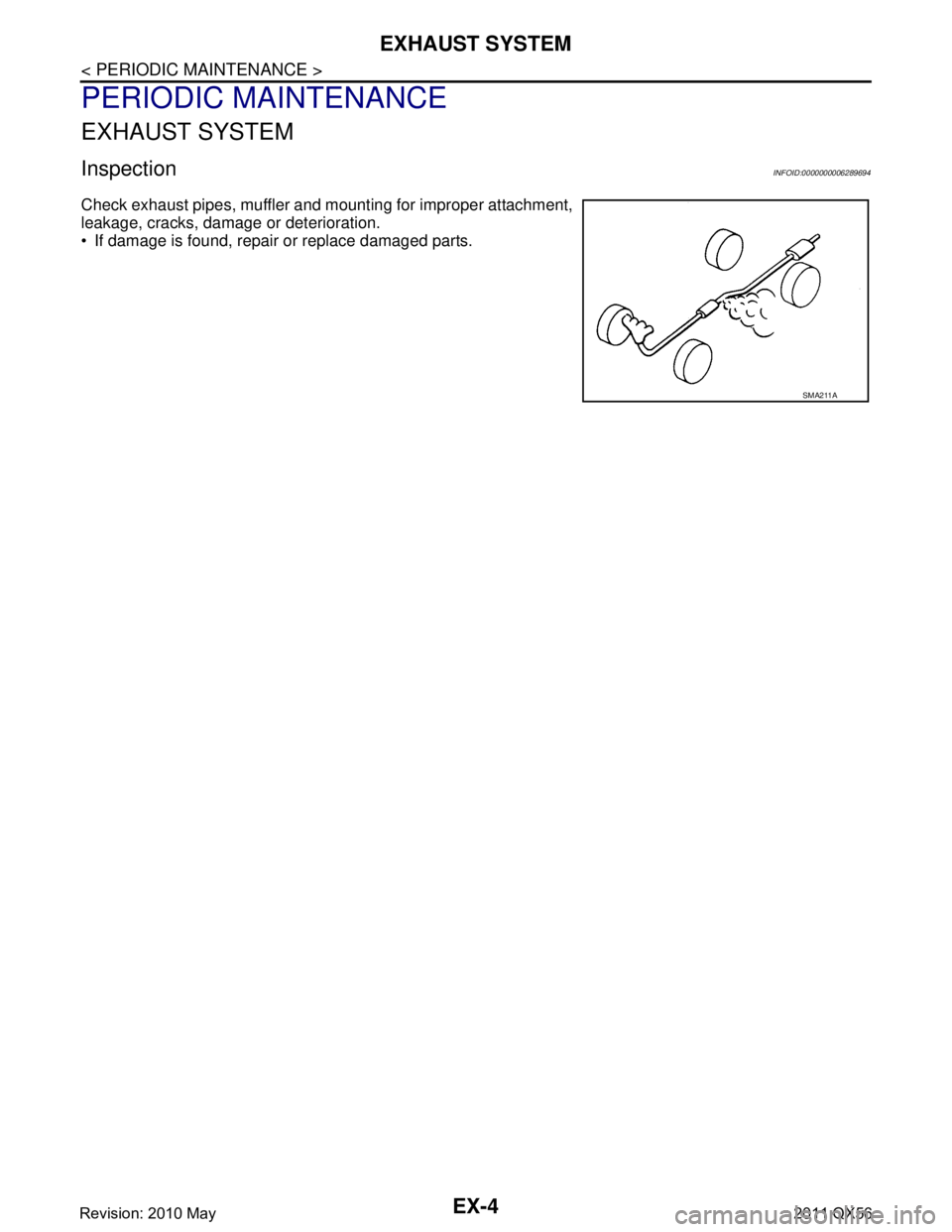
Check exhaust pipes, muffler and mounting for improper attachment,
leakage, cracks, damage or deterioration.
• If damage is found, repair or replace damaged parts.
SMA211A
Revision: 2010 May2011 QX56
Page 2713 of 5598

EXL-3
C
DE
F
G H
I
J
K
M A
B
EXL
N
O P
EXTERIOR LAMP FUSE ................................ ....85
Diagnosis Procedure ........................................... ....85
HEADLAMP (HI) CIRCUIT .................................86
Component Function Check ................................ ....86
Diagnosis Procedure ...............................................86
HEADLAMP (LO) CIRCUIT ................................88
Component Function Check ................................ ....88
Diagnosis Procedure ...............................................88
XENON HEADLAMP ..........................................90
Diagnosis Procedure ........................................... ....90
HEADLAMP LEVELIZER CIRCUIT ...................91
Component Function Check ................................ ....91
Diagnosis Procedure ...............................................91
HEADLAMP AIMING SYSTEM (MANUAL) .......93
Component Inspection ........................................ ....93
FRONT FOG LAMP CIRCUIT ............................94
Component Function Check ................................ ....94
Diagnosis Procedure ...............................................94
PARKING LAMP CIRCUIT ............................. ....96
Component Function Check ................................ ....96
Diagnosis Procedure ...............................................96
FRONT SIDE MARKER LAMP CIRCUIT ...........98
Component Function Check ................................ ....98
Diagnosis Procedure ...............................................98
TURN SIGNAL LAMP CIRCUIT .........................99
Component Function Check ................................ ....99
Diagnosis Procedure ...............................................99
OPTICAL SENSOR ..........................................102
Component Function Check ................................ ..102
Diagnosis Procedure .............................................102
HAZARD SWITCH .......................................... ..105
Component Function Check ................................ ..105
Diagnosis Procedure .............................................105
AFS SWITCH ....................................................107
Component Function Check ................................ ..107
Diagnosis Procedure .............................................107
Component Inspection ..........................................108
TAIL LAMP CIRCUIT .......................................109
BODY SIDE ........................................................... ..109
BODY SIDE : Component Function Check ...........109
BODY SIDE : Diagnosis Procedure ......................109
BACK DOOR SIDE ................................................ ..110
BACK DOOR SIDE : Component Function Check ..110
BACK DOOR SIDE : Diagnosis Procedure ...........111
LICENSE PLATE LAMP CIRCUIT ...................112
Component Function Check ................................ ..112
Diagnosis Procedure .............................................112
SYMPTOM DIAGNOSIS ............................113
EXTERIOR LIGHTING SYSTEM SYMPTOMS .113
Symptom Table ................................................... ..113
NORMAL OPERATING CONDITION .............116
Description .............................................................116
BOTH SIDE HEADLAMPS DO NOT SWITCH
TO HIGH BEAM ..............................................
117
Description .............................................................117
Diagnosis Procedure .............................................117
BOTH SIDE HEADLAMPS (LO) ARE NOT
TURNED ON ...................................................
118
Description ........................................................... ..118
Diagnosis Procedure .............................................118
PARKING, LICENSE PLATE, SIDE MARKER
AND TAIL LAMPS ARE NOT TURNED ON ...
119
Description .............................................................119
Diagnosis Procedure .............................................119
BOTH SIDE FRONT FOG LAMPS ARE NOT
TURNED ON ...................................................
120
Description ........................................................... ..120
Diagnosis Procedure .............................................120
PERIODIC MAINTENANCE ......................121
HEADLAMP AIMING ADJUSTMENT .............121
description ........................................................... ..121
Aiming Adjustment Procedure ...............................122
FRONT FOG LAMP AIMING ADJUSTMENT .123
Description .............................................................123
Aiming Adjustment Procedure ...............................123
REMOVAL AND INSTALLATION .............125
FRONT COMBINATION LAMP ......................125
Exploded View ..................................................... ..125
Removal and Installation .......................................125
Replacement .........................................................126
Disassembly and Assembly ...................................127
FRONT FOG LAMP ........................................128
Exploded View .......................................................128
Removal and Installation .......................................128
Replacement .........................................................128
SIDE TURN SIGNAL LAMP ............................130
Exploded View .......................................................130
Removal and Installation .......................................130
OPTICAL SENSOR .........................................131
Exploded View .......................................................131
Removal and Installation .......................................131
LIGHTING & TURN SIGNAL SWITCH ...........132
Exploded View .......................................................132
Revision: 2010 May2011 QX56
Page 2715 of 5598
![INFINITI QX56 2011 Factory Repair Manual
PRECAUTIONSEXL-5
< PRECAUTION > [XENON TYPE]
C
D
E
F
G H
I
J
K
M A
B
EXL
N
O P
PRECAUTION
PRECAUTIONS
Precaution for Supplemental Restraint System (SRS) "AIR BAG" and "SEAT BELT
PRE-TENSIONER"
INFO INFINITI QX56 2011 Factory Repair Manual
PRECAUTIONSEXL-5
< PRECAUTION > [XENON TYPE]
C
D
E
F
G H
I
J
K
M A
B
EXL
N
O P
PRECAUTION
PRECAUTIONS
Precaution for Supplemental Restraint System (SRS) "AIR BAG" and "SEAT BELT
PRE-TENSIONER"
INFO](/img/42/57033/w960_57033-2714.png)
PRECAUTIONSEXL-5
< PRECAUTION > [XENON TYPE]
C
D
E
F
G H
I
J
K
M A
B
EXL
N
O P
PRECAUTION
PRECAUTIONS
Precaution for Supplemental Restraint System (SRS) "AIR BAG" and "SEAT BELT
PRE-TENSIONER"
INFOID:0000000006450052
The Supplemental Restraint System such as “A IR BAG” and “SEAT BELT PRE-TENSIONER”, used along
with a front seat belt, helps to reduce the risk or severi ty of injury to the driver and front passenger for certain
types of collision. This system includes seat belt switch inputs and dual stage front air bag modules. The SRS
system uses the seat belt switches to determine the front air bag deployment, and may only deploy one front
air bag, depending on the severity of a collision and whether the front occupants are belted or unbelted.
Information necessary to service the system safely is included in the “SRS AIR BAG” and “SEAT BELT” of this
Service Manual.
WARNING:
• To avoid rendering the SRS inoper ative, which could increase the risk of personal injury or death in
the event of a collision that would result in air ba g inflation, all maintenance must be performed by
an authorized NISSAN/INFINITI dealer.
Improper maintenance, including in correct removal and installation of the SRS, can lead to personal
injury caused by unintentional act ivation of the system. For removal of Spiral Cable and Air Bag
Module, see the “SRS AIR BAG”.
Do not use electrical test equipm ent on any circuit related to the SRS unless instructed to in this
Service Manual. SRS wiring harnesses can be identi fied by yellow and/or orange harnesses or har-
ness connectors.
PRECAUTIONS WHEN USING POWER TOOLS (AIR OR ELECTRIC) AND HAMMERS
WARNING:
When working near the Air Bag Diagnosis Sensor Unit or other Air Bag System sensors with the
ignition ON or engine running, DO NOT use air or electric power tools or strike near the sensor(s)
with a hammer. Heavy vibration could activate the sensor(s) and deploy the air bag(s), possibly
causing serious injury.
When using air or electric power tools or hammers , always switch the ignition OFF, disconnect the
battery, and wait at least 3 minutes before performing any service.
Revision: 2010 May2011 QX56
Page 2831 of 5598
![INFINITI QX56 2011 Factory Repair Manual
HEADLAMP AIMING ADJUSTMENTEXL-121
< PERIODIC MAINTENANCE > [XENON TYPE]
C
D
E
F
G H
I
J
K
M A
B
EXL
N
O P
PERIODIC MAINTENANCE
HEADLAMP AIMING ADJUSTMENT
descriptionINFOID:0000000006213990
preparatio INFINITI QX56 2011 Factory Repair Manual
HEADLAMP AIMING ADJUSTMENTEXL-121
< PERIODIC MAINTENANCE > [XENON TYPE]
C
D
E
F
G H
I
J
K
M A
B
EXL
N
O P
PERIODIC MAINTENANCE
HEADLAMP AIMING ADJUSTMENT
descriptionINFOID:0000000006213990
preparatio](/img/42/57033/w960_57033-2830.png)
HEADLAMP AIMING ADJUSTMENTEXL-121
< PERIODIC MAINTENANCE > [XENON TYPE]
C
D
E
F
G H
I
J
K
M A
B
EXL
N
O P
PERIODIC MAINTENANCE
HEADLAMP AIMING ADJUSTMENT
descriptionINFOID:0000000006213990
preparation before adjusting
NOTE:
for details, refer to the regulations in your own country.
perform aiming if the vehicle front body has been repaired and/or the headlamp assembly has been
replaced.
before performing aiming adjustment, check the following. adjust the tire pressure to the specification.
fill with fuel, engine coolant and each oil.
maintain the unloaded vehicle condition. (remove luggage from the passenger compartment and the lug- gage room.)
NOTE:
do not remove the temporary tire, jack and on-vehicle tool.
wipe out dirt on the headlamp.
CAUTION:
never use organic solvent (thinner, gasoline etc.)
ride alone on the driver seat.
aiming adjustment screw
JMLIA1319ZZ
A. Headlamp RH HI /LO (UP/DOWN)
adjustment screw B. Headlamp LH HI/LO (UP/DOWN)
adjustment screw
: Vehicle center
Revision: 2010 May2011 QX56