service INFINITI QX56 2011 Factory Manual Online
[x] Cancel search | Manufacturer: INFINITI, Model Year: 2011, Model line: QX56, Model: INFINITI QX56 2011Pages: 5598, PDF Size: 94.53 MB
Page 944 of 5598
CO-2
< PRECAUTION >
PRECAUTIONS
PRECAUTION
PRECAUTIONS
Precaution for Supplemental Restraint System (SRS) "AIR BAG" and "SEAT BELT
PRE-TENSIONER"
INFOID:0000000006417198
The Supplemental Restraint System such as “A IR BAG” and “SEAT BELT PRE-TENSIONER”, used along
with a front seat belt, helps to reduce the risk or severi ty of injury to the driver and front passenger for certain
types of collision. This system includes seat belt switch inputs and dual stage front air bag modules. The SRS
system uses the seat belt switches to determine the front air bag deployment, and may only deploy one front
air bag, depending on the severity of a collision and w hether the front occupants are belted or unbelted.
Information necessary to service the system safely is included in the “SRS AIR BAG” and “SEAT BELT” of this
Service Manual.
WARNING:
• To avoid rendering the SRS inopera tive, which could increase the risk of personal injury or death in
the event of a collision that would result in air bag inflation, all maintenance must be performed by
an authorized NISS AN/INFINITI dealer.
Improper maintenance, including in correct removal and installation of the SRS, can lead to personal
injury caused by unintent ional activation of the system. For re moval of Spiral Cable and Air Bag
Module, see the “SRS AIR BAG”.
Do not use electrical test equipmen t on any circuit related to the SRS unless instructed to in this
Service Manual. SRS wiring harnesses can be identi fied by yellow and/or orange harnesses or har-
ness connectors.
PRECAUTIONS WHEN USING POWER TOOLS (AIR OR ELECTRIC) AND HAMMERS
WARNING:
When working near the Air Bag Diagnosis Sensor Unit or other Air Bag System sensors with the ignition ON or engine running, DO NOT use air or electric power tools or strike near the sensor(s)
with a hammer. Heavy vibration could activate the sensor(s) and deploy the air bag(s), possibly
causing serious injury.
When using air or electric power tools or hammers , always switch the ignition OFF, disconnect the
battery, and wait at least 3 minu tes before performing any service.
Revision: 2010 May2011 QX56
Page 945 of 5598
PREPARATIONCO-3
< PREPARATION >
C
DE
F
G H
I
J
K L
M A
CO
NP
O
PREPARATION
PREPARATION
Commercial Service ToolsINFOID:0000000006289653
Tool name
Description
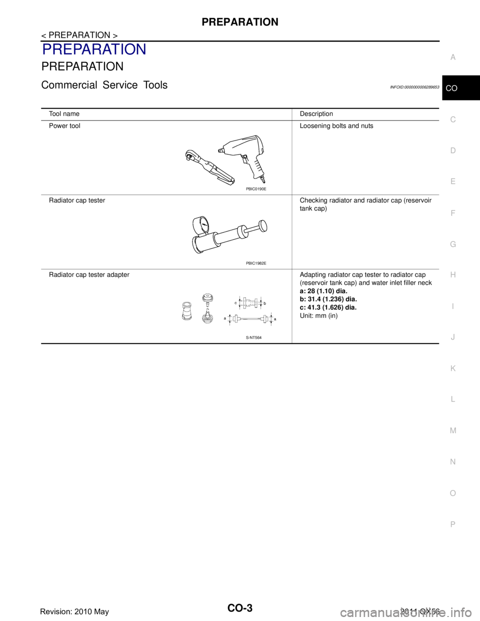
Power tool Loosening bolts and nuts
Radiator cap tester Checking radiator and radiator cap (reservoir tank cap)
Radiator cap tester adapter Adapting radiator cap tester to radiator cap (reservoir tank cap) and water inlet filler neck
a: 28 (1.10) dia.
b: 31.4 (1.236) dia.
c: 41.3 (1.626) dia.
Unit: mm (in)
PBIC0190E
PBIC1982E
S-NT564
Revision: 2010 May2011 QX56
Page 950 of 5598
CO-8
< PERIODIC MAINTENANCE >
ENGINE COOLANT
PERIODIC MAINTENANCE
ENGINE COOLANT
InspectionINFOID:0000000006289657
LEVEL
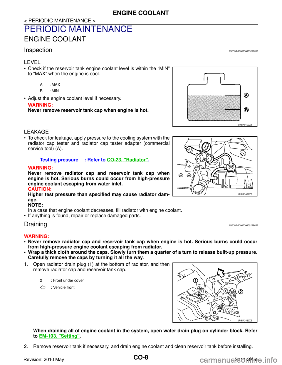
Check if the reservoir tank engine coolant level is within the “MIN”to “MAX” when the engine is cool.
Adjust the engine coolant level if necessary. WARNING:
Never remove reservoir tank cap when engine is hot.
LEAKAGE
To check for leakage, apply pressure to the cooling system with theradiator cap tester and radiator cap tester adapter (commercial
service tool) (A).
WARNING:
Never remove radiator cap and reservoir tank cap when
engine is hot. Serious burns could occur from high-pressure
engine coolant escaping from water inlet.
CAUTION:
Higher test pressure than specified may cause radiator dam-
age.
NOTE:
In a case that engine coolant decreas es, fill radiator with engine coolant.
If anything is found, repair or replace damaged parts.
DrainingINFOID:0000000006289658
WARNING:
Never remove radiator cap and reservoir tank cap when engine is hot. Serious burns could occur
from high-pressure engine co olant escaping from radiator.
Wrap a thick cloth around the caps. Slowly turn them a quarter of a turn to release built-up pressure.
Carefully remove the caps by turning it all the way.
1. Open radiator drain plug (1) at the bottom of radiator, and then remove radiator cap and reservoir tank cap.
When draining all of engine cool ant in the system, open water drai n plug on cylinder block. Refer
to EM-103, "
Setting".
2. Remove reservoir tank if necessary, and drain engine coolant and clean reservoir tank before installing.
A: MAX
B: MIN
JPBIA0102ZZ
Testing pressure : Refer to CO-23, "Radiator".
JPBIA3432ZZ
2 : Front under cover
: Vehicle front
JPBIA3430ZZ
Revision: 2010 May2011 QX56
Page 953 of 5598
RADIATORCO-11
< PERIODIC MAINTENANCE >
C
DE
F
G H
I
J
K L
M A
CO
NP
O
RADIATOR
RESERVOIR TANK CAP
RESERVOIR TANK CAP : InspectionINFOID:0000000006289661
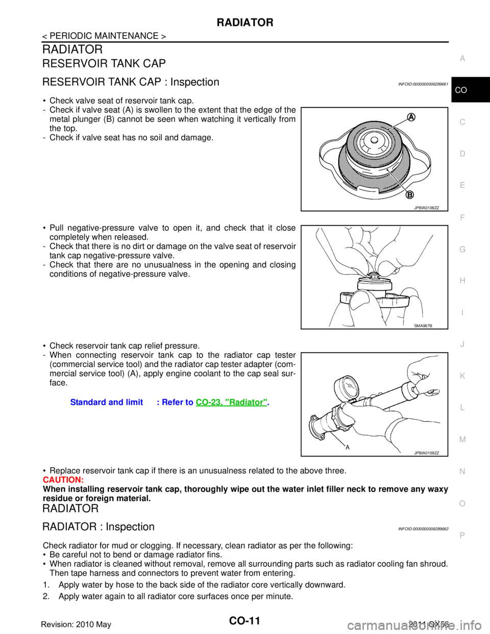
Check valve seat of reservoir tank cap.
- Check if valve seat (A) is swollen to the extent that the edge of the
metal plunger (B) cannot be seen when watching it vertically from
the top.
- Check if valve seat has no soil and damage.
Pull negative-pressure valve to open it, and check that it close completely when released.
- Check that there is no dirt or dam age on the valve seat of reservoir
tank cap negative-pressure valve.
- Check that there are no unusualness in the opening and closing conditions of negative-pressure valve.
Check reservoir tank cap relief pressure.
- When connecting reservoir tank cap to the radiator cap tester (commercial service tool) and the r adiator cap tester adapter (com-
mercial service tool) (A), apply engine coolant to the cap seal sur-
face.
Replace reservoir tank cap if there is an unusualness related to the above three.
CAUTION:
When installing reservoir tank cap , thoroughly wipe out the water inlet filler neck to remove any waxy
residue or foreign material.
RADIATOR
RADIATOR : InspectionINFOID:0000000006289662
Check radiator for mud or clogging. If neces sary, clean radiator as per the following:
Be careful not to bend or damage radiator fins.
When radiator is cleaned without removal, remove all surrounding parts such as radiator cooling fan shroud. Then tape harness and connectors to prevent water from entering.
1. Apply water by hose to the back side of the radiator core vertically downward.
2. Apply water again to all radiator core surfaces once per minute.
JPBIA0108ZZ
SMA967B
Standard and limit : Refer to CO-23, "Radiator".
JPBIA0109ZZ
Revision: 2010 May2011 QX56
Page 957 of 5598
RADIATORCO-15
< REMOVAL AND INSTALLATION >
C
DE
F
G H
I
J
K L
M A
CO
NP
O
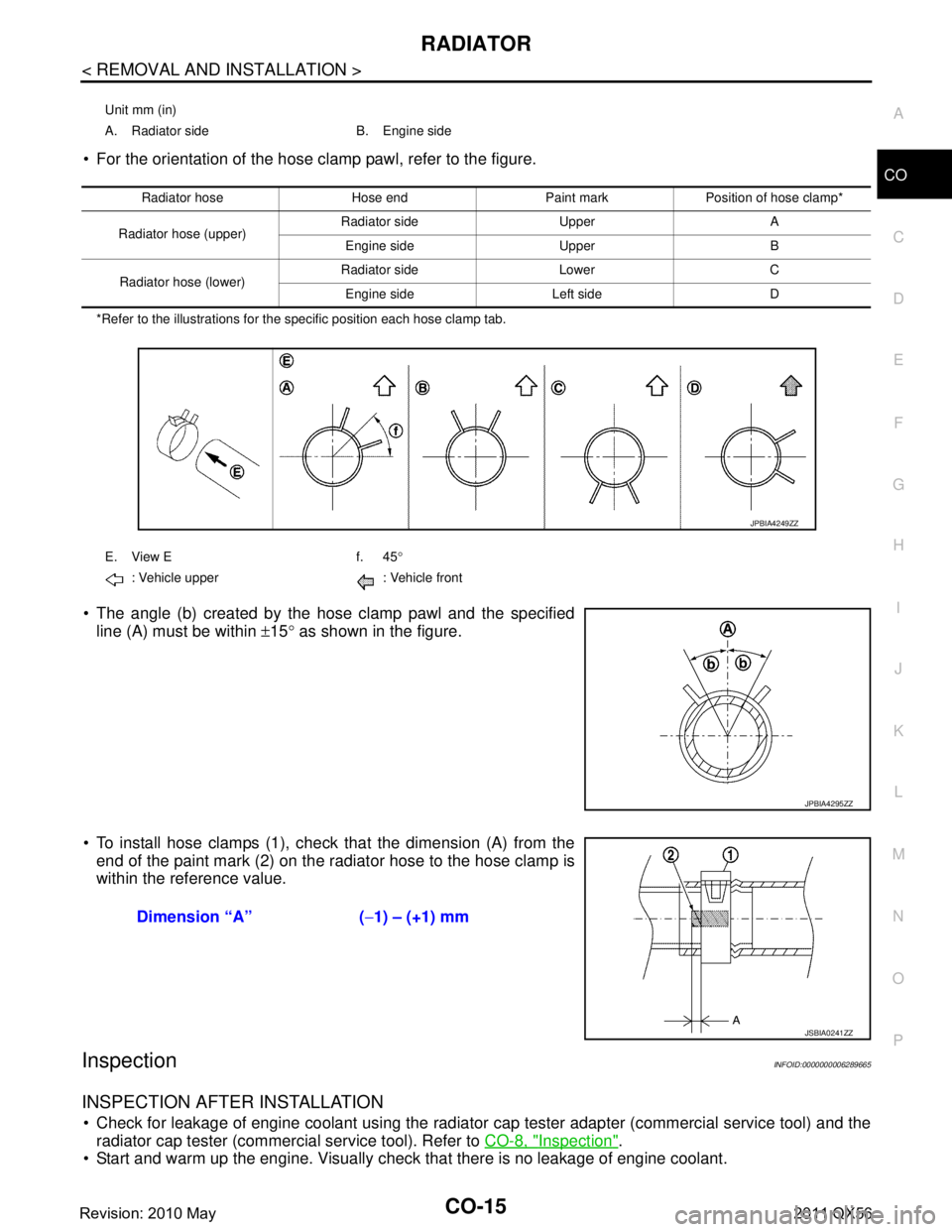
For the orientation of the hose clamp pawl, refer to the figure.
*Refer to the illustrations for the specific position each hose clamp tab.
The angle (b) created by the hose clamp pawl and the specified
line (A) must be within ±15 ° as shown in the figure.
To install hose clamps (1), check that the dimension (A) from the end of the paint mark (2) on the radiator hose to the hose clamp is
within the reference value.
InspectionINFOID:0000000006289665
INSPECTION AFTER INSTALLATION
Check for leakage of engine coolant using the radiator cap tester adapter (commercial service tool) and the
radiator cap tester (commercial service tool). Refer to CO-8, "
Inspection".
Start and warm up the engine. Visually check that there is no leakage of engine coolant.
Unit mm (in)
A. Radiator side B. Engine side
Radiator hose Hose end Paint mark Position of hose clamp*
Radiator hose (upper) Radiator side Upper A
Engine side Upper B
Radiator hose (lower) Radiator side Lower C
Engine side Left side D
E. View E f. 45 °
: Vehicle upper : Vehicle front
JPBIA4249ZZ
JPBIA4295ZZ
Dimension “A” ( −1) – (+1) mm
JSBIA0241ZZ
Revision: 2010 May2011 QX56
Page 960 of 5598
CO-18
< REMOVAL AND INSTALLATION >
WATER PUMP
WATER PUMP
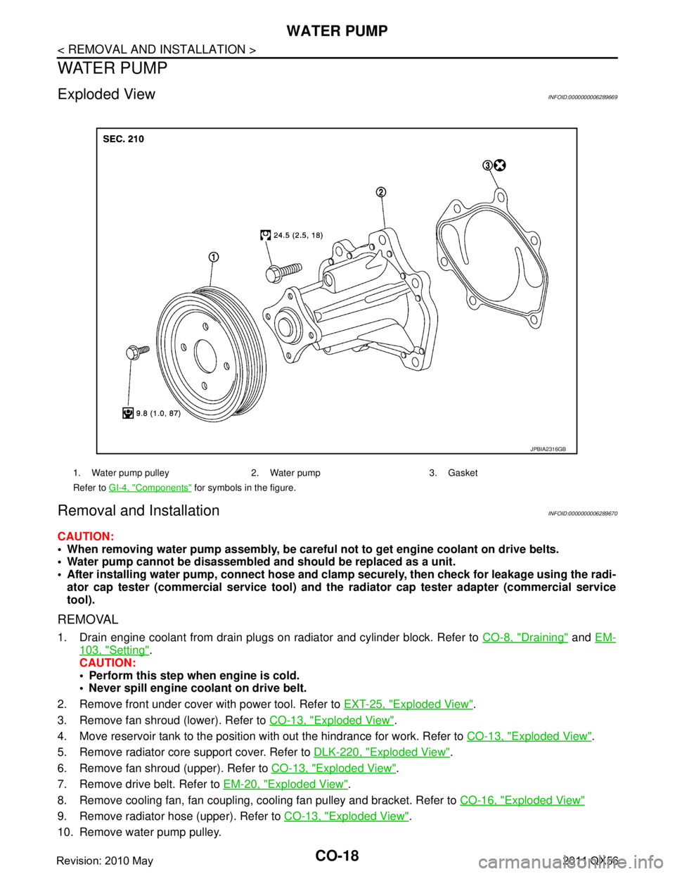
Exploded ViewINFOID:0000000006289669
Removal and InstallationINFOID:0000000006289670
CAUTION:
When removing water pump assembly, be careful not to get engine coolant on drive belts.
Water pump cannot be disassembled and should be replaced as a unit.
After installing water pump, co nnect hose and clamp securely, then check for leakage using the radi-
ator cap tester (commercial service tool) and the radiator cap tester adapter (commercial service
tool).
REMOVAL
1. Drain engine coolant from drain plugs on radiator and cylinder block. Refer to CO-8, "Draining" and EM-
103, "Setting".
CAUTION:
Perform this step when engine is cold.
Never spill engine coolant on drive belt.
2. Remove front under cover with power tool. Refer to EXT-25, "
Exploded View".
3. Remove fan shroud (lower). Refer to CO-13, "
Exploded View".
4. Move reservoir tank to the position with out the hindrance for work. Refer to CO-13, "
Exploded View".
5. Remove radiator core support cover. Refer to DLK-220, "
Exploded View".
6. Remove fan shroud (upper). Refer to CO-13, "
Exploded View".
7. Remove drive belt. Refer to EM-20, "
Exploded View".
8. Remove cooling fan, fan coupling, cooling fan pulley and bracket. Refer to CO-16, "
Exploded View"
9. Remove radiator hose (upper). Refer to CO-13, "Exploded View".
10. Remove water pump pulley.
1. Water pump pulley 2. Water pump 3. Gasket
Refer to GI-4, "
Components" for symbols in the figure.
JPBIA2316GB
Revision: 2010 May2011 QX56
Page 961 of 5598
WATER PUMPCO-19
< REMOVAL AND INSTALLATION >
C
DE
F
G H
I
J
K L
M A
CO
NP
O
11. Remove water pump. Refer to
CO-18, "Exploded View".
Engine coolant will leak from cylinder block, so have a receptacle ready under vehicle.
CAUTION:
Handle the water pump vane so that it does not contact any other parts.
Never disassemble water pump.
INSTALLATION
Install in the reverse order of removal.
InspectionINFOID:0000000006289671
INSPECTION AFTER REMOVAL
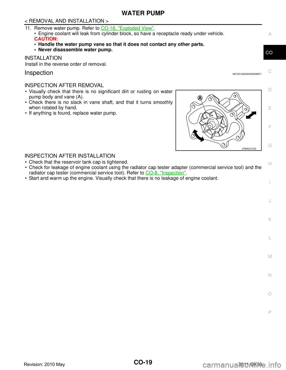
Visually check that there is no significant dirt or rusting on water pump body and vane (A).
Check there is no slack in vane shaft, and that it turns smoothly when rotated by hand.
If anything is found, replace water pump.
INSPECTION AFTER INSTALLATION
Check that the reservoir tank cap is tightened.
Check for leakage of engine coolant using the radiator cap tester adapter (commercial service tool) and the
radiator cap tester (commercial service tool). Refer to CO-8, "
Inspection".
Start and warm up the engine. Visually check that there is no leakage of engine coolant.
JPBIA2315ZZ
Revision: 2010 May2011 QX56
Page 964 of 5598
CO-22
< REMOVAL AND INSTALLATION >
WATER INLET AND THERMOSTAT ASSEMBLY
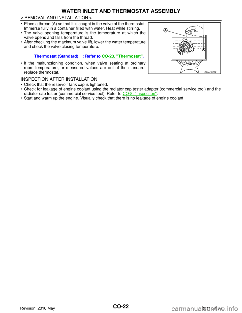
Place a thread (A) so that it is caught in the valve of the thermostat.Immerse fully in a container filled with water. Heat while stirring.
The valve opening temperature is the temperature at which the
valve opens and falls from the thread.
After checking the maximum valve lift, lower the water temperature and check the valve closing temperature.
If the malfunctioning condition, when valve seating at ordinary room temperature, or measured values are out of the standard,
replace thermostat.
INSPECTION AFTER INSTALLATION
Check that the reservoir tank cap is tightened.
Check for leakage of engine coolant using the radiator cap tester adapter (commercial service tool) and the
radiator cap tester (commercial service tool). Refer to CO-8, "
Inspection".
Start and warm up the engine. Visually chec k that there is no leakage of engine coolant.
Thermostat (Standard) : Refer to
CO-23, "
Thermostat".
JPBIA2313ZZ
Revision: 2010 May2011 QX56
Page 965 of 5598
SERVICE DATA AND SPECIFICATIONS (SDS)
CO-23
< SERVICE DATA AND SPECIFICATIONS (SDS)
C
D E
F
G H
I
J
K L
M A
CO
NP
O
SERVICE DATA AND SPECIFICATIONS (SDS)
SERVICE DATA AND SPECIFICATIONS (SDS)
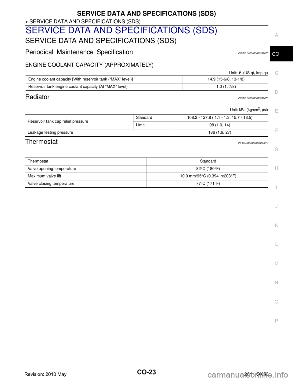
Periodical Maintenance SpecificationINFOID:0000000006289675
ENGINE COOLANT CAPACITY (APPROXIMATELY)
Unit: (US qt, Imp qt)
RadiatorINFOID:0000000006289676
Unit: kPa (kg/cm2, psi)
ThermostatINFOID:0000000006289677
Engine coolant capacity [With reservoir tank (“MAX” level)] 14.9 (15-6/8, 13-1/8)
Reservoir tank engine coolant capacity (At “MAX” level) 1.0 (1, 7/8)
Reservoir tank cap relief pressure
Standard 108.2 - 127.8 ( 1.1 - 1.3, 15.7 - 18.5)
Limit 98 (1.0, 14)
Leakage testing pressure 186 (1.9, 27)
ThermostatStandard
Valve opening temperature 82 °C (180 °F)
Maximum valve lift 10.0 mm/95 °C (0.394 in/203 °F)
Valve closing temperature 77 °C (171 °F)
Revision: 2010 May2011 QX56
Page 966 of 5598
DAS-1
CRUISE CONTROL & DRIVER ASSISTANCE
C
DE
F
G H
I
J
K L
M B
DAS
SECTION DAS
N
P A
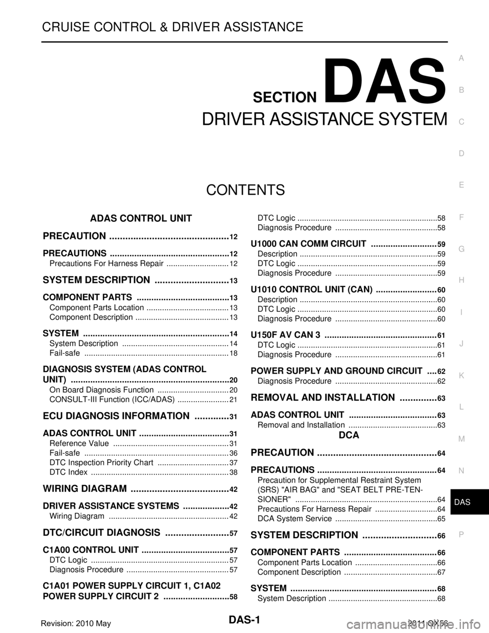
CONTENTS
DRIVER ASSISTANCE SYSTEM
ADAS CONTROL UNIT
PRECAUTION ................ ..............................
12
PRECAUTIONS .............................................. ....12
Precautions For Harness Repair ......................... ....12
SYSTEM DESCRIPTION .............................13
COMPONENT PARTS ................................... ....13
Component Parts Location .................................. ....13
Component Description ...........................................13
SYSTEM .............................................................14
System Description ............................................. ....14
Fail-safe ..................................................................18
DIAGNOSIS SYSTEM (ADAS CONTROL
UNIT) ..................................................................
20
On Board Diagnosis Function ............................. ....20
CONSULT-III Function (ICC/ADAS) ........................21
ECU DIAGNOSIS INFORMATION ..............31
ADAS CONTROL UNIT .................................. ....31
Reference Value ................................................. ....31
Fail-safe ..................................................................36
DTC Inspection Priority Chart .................................37
DTC Index ...............................................................38
WIRING DIAGRAM ......................................42
DRIVER ASSISTANCE SYSTEMS ................ ....42
Wiring Diagram ................................................... ....42
DTC/CIRCUIT DIAGNOSIS .........................57
C1A00 CONTROL UNIT ................................. ....57
DTC Logic ........................................................... ....57
Diagnosis Procedure ...............................................57
C1A01 POWER SUPPLY CIRCUIT 1, C1A02
POWER SUPPLY CIRCUIT 2 ............................
58
DTC Logic ............................................................ ....58
Diagnosis Procedure ...............................................58
U1000 CAN COMM CIRCUIT ...........................59
Description ...............................................................59
DTC Logic ................................................................59
Diagnosis Procedure ...............................................59
U1010 CONTROL UNIT (CAN) .........................60
Description ...............................................................60
DTC Logic ................................................................60
Diagnosis Procedure ...............................................60
U150F AV CAN 3 ..............................................61
DTC Logic ................................................................61
Diagnosis Procedure ...............................................61
POWER SUPPLY AND GROUND CIRCUIT ....62
Diagnosis Procedure ...............................................62
REMOVAL AND INSTALLATION ...............63
ADAS CONTROL UNIT ....................................63
Removal and Installation ..................................... ....63
DCA
PRECAUTION ............... ...............................
64
PRECAUTIONS .................................................64
Precaution for Supplemental Restraint System
(SRS) "AIR BAG" and "SEAT BELT PRE-TEN-
SIONER" ............................................................. ....
64
Precautions For Harness Repair .............................64
DCA System Service ...............................................65
SYSTEM DESCRIPTION .............................66
COMPONENT PARTS ......................................66
Component Parts Location .................................. ....66
Component Description ...........................................67
SYSTEM ............................................................68
System Description .............................................. ....68
Revision: 2010 May2011 QX56