fuel door INFINITI QX56 2011 Factory Service Manual
[x] Cancel search | Manufacturer: INFINITI, Model Year: 2011, Model line: QX56, Model: INFINITI QX56 2011Pages: 5598, PDF Size: 94.53 MB
Page 1 of 5598
A
B
D
E
F
G
H
I
J
K
L
M
N
P
O
C
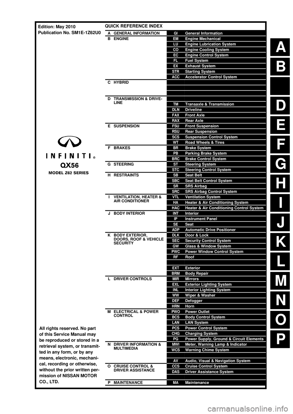
QUICK REFERENCE INDEX
AGENERAL INFORMATIONGIGeneral Information
BENGINEEMEngine Mechanical
LUEngine Lubrication System
COEngine Cooling System
ECEngine Control System
FLFuel System
EXExhaust System
STRStarting System
ACCAccelerator Control System
CHYBRIDHBCHybrid Control System
HBBHybrid Battery System
HBRHybrid Brake System
DTRANSMISSION & DRIVE-
LINECLClutch
TMTransaxle & Transmission
DLNDriveline
FAXFront Axle
RAXRear Axle
ESUSPENSIONFSUFront Suspension
RSURear Suspension
SCSSuspension Control System
WTRoad Wheels & Tires
FBRAKESBRBrake System
PBParking Brake System
BRCBrake Control System
GSTEERINGSTSteering System
STCSteering Control System
HRESTRAINTSSBSeat Belt
SBCSeat Belt Control System
SRSRS Airbag
SRCSRS Airbag Control System
IVENTILATION, HEATER &
AIR CONDITIONERVTLVentilation System
HAHeater & Air Conditioning System
HACHeater & Air Conditioning Control System
JBODY INTERIORINTInterior
IPInstrument Panel
SESeat
ADPAutomatic Drive Positioner
KBODY EXTERIOR,
DOORS, ROOF & VEHICLE
SECURITYDLKDoor & Lock
SECSecurity Control System
GWGlass & Window System
PWCPower Window Control System
RFRoof
HDHood
EXTExterior
BRMBody Repair
LDRIVER CONTROLSMIRMirrors
EXLExterior Lighting System
INLInterior Lighting System
WWWiper & Washer
DEFDefogger
HRNHorn
MELECTRICAL & POWER
CONTROLPWOPower Outlet
BCSBody Control System
LANLAN System
PCSPower Control System
CHGCharging System
PGPower Supply, Ground & Circuit Elements
NDRIVER INFORMATION &
MULTIMEDIAMWIMeter, Warning Lamp & Indicator
WCSWarning Chime System
SNSonar System
AVAudio, Visual & Navigation System
OCRUISE CONTROL &
DRIVER ASSISTANCECCSCruise Control System
DASDriver Assistance System
DMSDrive Mode System
PMAINTENANCEMAMaintenance
All rights reserved. No part
of this Service Manual may
be reproduced or stored in a
retrieval system, or transmit-
ted in any form, or by any
means, electronic, mechani-
cal, recording or otherwise,
without the prior written per-
mission of NISSAN MOTOR
CO., LTD.
Edition: May 2010
Publication No. SM1E-1Z62U0
Page 435 of 5598

BCS
BCM
BCS-47
< ECU DIAGNOSIS INFORMATION >
C
D E
F
G H
I
J
K L
B A
O P
N
55
(G) Ground Rear door UNLOCK Output Rear door UNLOCK (Actuator is acti-
vated)
12 V
Other then UNLOCK (Ac-
tuator is not activated) 0 V
56
(W/R) Ground Interior room lamp
power supply OutputInterior room lamp battery saver is activated.
(Cuts the interior room
lamp power supply) 0 V
Interior room lamp battery saver is not acti-
vated.
(Outputs the interior room lamp power sup-
ply) 12 V
57
(LG) Ground Battery power sup-
ply
Input Ignition switch OFF Battery voltage
59
(G) Ground Passenger door UN-
LOCK
Output Passenger door UNLOCK (Actuator is acti-
vated)
12 V
Other then UNLOCK (Ac-
tuator is not activated) 0 V
60
(G) Ground Turn signal LH Output Ignition switch
ONTurn signal switch OFF 0 V
Turn signal switch LH
6.0 - 7.0 V
61
(G/Y) Ground Turn signal RH Output Ignition switch
ONTurn signal switch OFF 0 V
Turn signal switch RH
6.0 - 7.0 V
62
(R) Ground Step lamp Output Step lamp ON 0 V
OFF 12 V
63
(BR) Ground Interior room lamp
timer control
OutputInterior room
lamp OFF 12 V
ON 0 V
64
(GR/R) Ground Cranking request input
Ignition switch
ONEngine stopped (Selector
lever is in P position)
0 V
Engine stopped (Selector
lever is not in P position) 12 V
Engine running 12 V
65
(R) Ground All doors, fuel lid
LOCK
Output All doors, fuel lid LOCK (Actuator is activat-
ed)
12 V
Other then LOCK (Actua-
tor is not activated) 0 V
Terminal No.
(Wire color) Description
Condition
Va l u e
(Approx.)
Signal name Input/
Output
+ −
PKIC6370E
PKIC6370E
Revision: 2010 May2011 QX56
Page 436 of 5598

BCS-48
< ECU DIAGNOSIS INFORMATION >
BCM
66
(V) Ground Driver door, fuel lid
UNLOCK OutputDriver door, fuel
lid UNLOCK (Actuator is acti-
vated)
12 V
Other then UNLOCK (Ac-
tuator is not activated) 0 V
67
(B) Ground Ground Output Ignition switch ON 0 V
68
(Y) Ground P/W power supply
(IGN)
Output Ignition switch ON 12 V
69
(W) Ground
P/W power supply
(BAT) Output Ignition switch OFF 12 V
70
(Y) Ground Battery power sup-
ply Input Ignition switch OFF Battery voltage
72
(P) Ground Puddle lamp control Output Puddle lamp OFF 12 V
ON 0 V
73
(W) Ground ON indicator lamp Output Ignition switch OFF (LOCK indicator is
not illuminated)
Battery voltage
ON 0 V
74
(Y/B) Ground Trailer turn signal
RH control
OutputIgnition switch
ON Turn signal switch OFF Battery voltage
Turn signal switch RH
6.0 - 7.0 V
75
(LG/R) Ground
Driver door request
switch Input
Driver door re-
quest switch ON (Pressed) 0 V
OFF (Not pressed) 12 V
76
(P/L) Ground
Passenger door re-
quest switch Input
Passenger door
request switch ON (Pressed) 0 V
OFF (Not pressed) 12 V
77
(O/L) Ground Trailer turn signal LH
control
OutputIgnition switch
ON Turn signal switch OFF Battery voltage
Turn signal switch LH
6.0 - 7.0 V
Te r m i n a l N o .
(Wire color) Description
Condition Va l u e
(Approx.)
Signal name Input/
Output
+ −
PKIC6370E
PKIC6370E
Revision: 2010 May2011 QX56
Page 687 of 5598

BRM-12
< PREPARATION >
BODY COMPONENT PARTS
NOTE:
For the parts without a number described in the figure, it is supplied only with the assembly part that the part is included with.
Tensile strength column shows the largest strength value of a part in the component part. No. Parts name
Tensile strength
(MPa) Both sided anti-corrosive
precoated steel sections
1. Hood Under 440×
2. Front fender (RH & LH) Under 440 ×
3. Inner side roof rail (RH & LH) 590 —
4. Upper inner front pillar (RH & LH) c. T=1.6 mm
(0.063 in)
980
caution—
5. Inner center pillar (RH & LH) d. T=1.6 mm
(0.063 in)
980
caution×
6. Center sill reinforcement assembly (RH & LH) Under 440 ×
7. Side body assembly (RH & LH) Refer to No.8 −13
8. Upper front pillar reinforcement (RH & LH) 590 —
9. Lower center pillar brace (RH & LH) e. T=1.8 mm
(0.071 in)
980
caution—
10. Front pillar brace (RH & LH) 590 —
11. Outer sill reinforcement (RH & LH) 590 ×
12. Outer front side body (RH & LH) Under 440 ×
13. Front fender bracket assembly (RH & LH) Under 440 ×
14. Outer sill (RH & LH) Under 440 ×
15. Front door assembly (RH & LH) 440 ×
16. Outer front door panel (RH & LH) Under 440 ×
17. Rear door assembly (RH & LH) 440 ×
18. Outer rear door panel (RH & LH) Under 440 ×
19. Back pillar reinforcement (RH & LH) Under 440 —
20. Inner back pillar (RH & LH) Under 440 —
21. Inner rear side roof rail (RH & LH) Under 440 —
22. Inner rear pillar (RH & LH) 590 —
23. Lower inner rear pillar (RH & LH)v Under 440 —
24. Side panel reinforcement (RH & LH) Under 440 —
25. Outer rear wheelhouse (RH & LH) Under 440 ×
26. Inner rear wheelhouse (RH & LH) Under 440 ×
27. Outer rear wheelhouse extension (RH & LH) Under 440 ×
28. Roof assembly Under 440 —
29. Front roof rail 440 —
30. Roof bow No.3 Under 440 —
31. Roof bow No.4 Under 440 —
32. Roof bow No.5 Under 440 —
33. Rear roof rail 440 —
34. Rear fender (RH & LH) Under 440 ×
35. Back pillar assembly (RH & LH) Under 440 —
36. Rear fender bracket (RH & LH) Under 440 —
37. Fuel filler lid Under 440 ×
38. Rear fender extension (RH & LH) Under 440 ×
39. Back door Under 440 ×
Revision: 2010 May2011 QX56
Page 1539 of 5598
DLK-3
C
DE
F
G H
I
J
L
M A
B
DLK
N
O P
Diagnosis Procedure ...........................................
....
98
B2423 AUTOMATIC BACK DOOR MOTOR
OPERATION TIME .............................................
99
DTC Logic ........................................................... ....99
Diagnosis Procedure ...............................................99
B2424 CLOSURE CONDITION ........................100
DTC Logic ........................................................... ..100
Diagnosis Procedure .............................................100
Component Inspection ..........................................101
B2425 AUTOMATIC BACK DOOR CONTROL
UNIT ..................................................................
103
DTC Logic ........................................................... ..103
Diagnosis Procedure .............................................103
B2621 INSIDE ANTENNA ................................104
DTC Logic ........................................................... ..104
Diagnosis Procedure .............................................104
B2622 INSIDE ANTENNA ................................106
DTC Logic ........................................................... ..106
Diagnosis Procedure .............................................106
B2623 INSIDE ANTENNA ................................108
DTC Logic ........................................................... ..108
Diagnosis Procedure .............................................108
B2626 OUTSIDE ANTENNA ............................110
DTC Logic ........................................................... ..110
Diagnosis Procedure .............................................110
B2627 OUTSIDE ANTENNA ............................112
DTC Logic ........................................................... ..112
Diagnosis Procedure .............................................112
B2628 OUTSIDE ANTENNA ............................114
DTC Logic ........................................................... ..114
Diagnosis Procedure .............................................114
POWER SUPPLY AND GROUND CIRCUIT ....116
AUTOMATIC BACK DOOR CONTROL UNIT ...... ..116
AUTOMATIC BACK DOOR CONTROL UNIT : Di-
agnosis Procedure ................................................
116
DOOR SWITCH ................................................117
Component Function Check .............................. ..117
Diagnosis Procedure .............................................117
Component Inspection ..........................................119
BACK DOOR SWITCH .....................................120
Component Function Check .............................. ..120
Diagnosis Procedure .............................................120
Component Inspection ..........................................121
DOOR LOCK AND UNLOCK SWITCH ............122
DRIVER SIDE ........................................................ ..122
DRIVER SIDE : Component Function Check ......122
DRIVER SIDE : Diagnosis Procedure ...................122
PASSENGER SIDE ..................................................122
PASSENGER SIDE :
Component Function Check .............................. ..
122
PASSENGER SIDE : Diagnosis Procedure ..........122
DOOR LOCK ACTUATOR ..............................123
DRIVER SIDE ......................................................... ..123
DRIVER SIDE : Component Function Check ......123
DRIVER SIDE : Diagnosis Procedure ...................123
PASSENGER SIDE ..................................................124
PASSENGER SIDE :
Component Function Check .............................. ..
124
PASSENGER SIDE : Diagnosis Procedure ..........124
REAR LH ................................................................ ..125
REAR LH : Component Function Check ..............125
REAR LH : Diagnosis Procedure ...........................125
REAR RH ............................................................... ..126
REAR RH : Component Function Check .............126
REAR RH : Diagnosis Procedure ..........................126
FUEL LID LOCK ACTUATOR ........................128
Component Function Check ................................128
Diagnosis Procedure .............................................128
UNLOCK SENSOR .........................................130
Component Function Check ................................130
Diagnosis Procedure .............................................130
Component Inspection ...........................................131
DOOR KEY CYLINDER SWITCH ...................132
Component Function Check ..................................132
Diagnosis Procedure .............................................132
Component Inspection ...........................................133
REMOTE KEYLESS ENTRY RECEIVER .......134
Component Function Check ................................134
Diagnosis Procedure .............................................134
DOOR REQUEST SWITCH ............................137
Component Function Check ................................137
Diagnosis Procedure .............................................137
Component Inspection ...........................................138
BACK DOOR REQUEST SWITCH .................139
Component Function Check ................................139
Diagnosis Procedure .............................................139
Component Inspection ...........................................140
BACK DOOR OPENER SWITCH ...................141
Component Function Check ................................141
Diagnosis Procedure .............................................141
Component Inspection ...........................................142
INTELLIGENT KEY WARNING BUZZER .......143
Component Function Check ................................143
Diagnosis Procedure .............................................143
Component Inspection ...........................................144
INTELLIGENT KEY .........................................145
Revision: 2010 May2011 QX56
Page 1541 of 5598

DLK-5
C
DE
F
G H
I
J
L
M A
B
DLK
N
O P
FUEL LID LOCK ACTUATOR DOES NOT OP-
ERATE ............................................................ ..
176
Diagnosis Procedure ........................................... ..176
IGNITION POSITION WARNING FUNCTION
DOES NOT OPERATE .....................................
177
Diagnosis Procedure ........................................... ..177
SELECTIVE UNLOCK FUNCTION DOES
NOT OPERATE ................................................
178
Diagnosis Procedure ........................................... ..178
AUTO DOOR LOCK OPERATION DOES NOT
OPERATE .........................................................
179
Diagnosis Procedure ........................................... ..179
VEHICLE SPEED SENSING AUTO LOCK
OPERATION DOES NOT OPERATE ..............
180
Diagnosis Procedure ........................................... ..180
IGN OFF INTERLOCK DOOR UNLOCK
FUNCTION DOES NOT OPERATE .................
181
Diagnosis Procedure ........................................... ..181
P RANGE INTERLOCK DOOR LOCK/UN-
LOCK FUNCTION DOES NOT OPERATE ......
182
Diagnosis Procedure ........................................... ..182
HAZARD AND HORN REMINDER DOES
NOT OPERATE ................................................
183
Diagnosis Procedure ........................................... ..183
HAZARD AND BUZZER REMINDER DOES
NOT OPERATE ................................................
184
Diagnosis Procedure ........................................... ..184
KEY REMINDER FUNCTION DOES NOT OP-
ERATE ..............................................................
185
Diagnosis Procedure ........................................... ..185
WELCOME LIGHT FUNCTION DOES NOT
OPERATE .........................................................
186
Diagnosis Procedure ........................................... ..186
OFF POSITION WARNING DOES NOT OP-
ERATE ..............................................................
188
Diagnosis Procedure ........................................... ..188
P POSITION WARNING DOES NOT OPER-
ATE ...................................................................
189
Description .......................................................... ..189
Diagnosis Procedure .............................................189
ACC WARNING DOES NOT OPERATE .........191
Description .......................................................... ..191
Diagnosis Procedure .............................................191
TAKE AWAY WARNING DOES NOT OPER-
ATE ...................................................................
192
Description .......................................................... ..192
Diagnosis Procedure .............................................192
KEY ID WARNING DOES NOT OPERATE ....194
Description ........................................................... ..194
Diagnosis Procedure .............................................194
INTELLIGENT KEY LOW BATTERY WARN-
ING DOES NOT OPERATE ............................
195
Description .............................................................195
Diagnosis Procedure .............................................195
DOOR LOCK OPERATION WARNING DOES
NOT OPERATE ...............................................
197
Diagnosis Procedure .............................................197
AUTOMATIC BACK DOOR OPERATION
DOES NOT OPERATE ....................................
198
ALL SWITCHES ..................................................... ..198
ALL SWITCHES : Description ...............................198
ALL SWITCHES : Diagnosis Procedure ................198
AUTOMATIC BACK DOOR SWITCH .................... ..199
AUTOMATIC BACK DOOR SWITCH : Descrip-
tion .........................................................................
199
AUTOMATIC BACK DOOR SWITCH : Diagnosis
Procedure ..............................................................
199
AUTOMATIC BACK DOOR CLOSE SWITCH ........199
AUTOMATIC BACK DOOR CLOSE SWITCH :
Description ........................................................... ..
199
AUTOMATIC BACK DOOR CLOSE SWITCH : Di-
agnosis Procedure .................................................
199
INTELLIGENT KEY ................................................ ..200
INTELLIGENT KEY : Description ..........................200
INTELLIGENT KEY : Diagnosis Procedure ......... ..200
BACK DOOR OPENER SWITCH .......................... ..200
BACK DOOR OPENER SWITCH : Description .....200
BACK DOOR OPENER SWITCH : Diagnosis Pro-
cedure ....................................................................
200
OPEN/CLOSURE FUNCTION ............................... ..201
OPEN/CLOSURE FUNCTION : Description .........201
OPEN/CLOSURE FUNCTION : Diagnosis Proce-
dure .......................................................................
201
OPEN FUNCTION .................................................. ..202
OPEN FUNCTION : Description ............................202
OPEN FUNCTION : Diagnosis Procedure ............202
CLOSURE FUNCTION .......................................... ..202
CLOSURE FUNCTION : Description .....................202
CLOSURE FUNCTION : Diagnosis Procedure .....203
AUTOMATIC BACK DOOR WARNING DOES
NOT OPERATE ...............................................
204
BUZZER ................................................................. ..204
BUZZER : Description ...........................................204
BUZZER : Diagnosis Procedure ............................204
HAZARD WARNING LAMP ................................... ..204
HAZARD WARNING LAMP : Description ..............204
Revision: 2010 May2011 QX56
Page 1543 of 5598
DLK-7
C
DE
F
G H
I
J
L
M A
B
DLK
N
O P
Exploded View ....................................................
..
243
DOOR LOCK ......................................................... ..243
DOOR LOCK : Removal and Installation ..............243
INSIDE HANDLE ................................................... ..243
INSIDE HANDLE : Removal and Installation ........244
OUTSIDE HANDLE ............................................... ..244
OUTSIDE HANDLE : Removal and Installation ....244
BACK DOOR LOCK .........................................246
Exploded View .................................................... ..246
DOOR LOCK ......................................................... ..246
DOOR LOCK : Removal and Installation ..............246
TOUCH SENSOR .................................................. ..246
TOUCH SENSOR : Removal and Installation .......246
BACK DOOR SUPPORT ROD .............................. ..247
BACK DOOR SUPPORT ROD : Removal and In-
stallation ................................................................
247
EMERGENCY LEVER ........................................... ..247
EMERGENCY LEVER : Unlock procedures .........247
FUEL FILLER LID OPENER ............................248
Exploded View .................................................... ..248
Removal and Installation .......................................248
KEY CYLINDER ...............................................250
GLOVE BOX LID KEY CYLINDER ....................... ..250
GLOVE BOX LID KEY CYLINDER : Removal and
Installation .............................................................
250
CAB MOUNTING INSULATOR ........................251
Exploded View .................................................... ..251
Removal and Installation .......................................251
DOOR SWITCH ................................................254
Removal and Installation ..................................... ..254
DOOR REQUEST SWITCH ..............................255
DRIVER SIDE ........................................................ ..255
DRIVER SIDE : Removal and Installation .............255
PASSENGER SIDE .................................................255
PASSENGER SIDE : Removal and Installation .. ..255
BACK DOOR ......................................................... ..255
BACK DOOR : Removal and Installation ..............255
INSIDE KEY ANTENNA ..................................256
INSTRUMENT CENTER ........................................ ..256
INSTRUMENT CENTER : Removal and Installa-
tion .........................................................................
256
CONSOLE .............................................................. ..256
CONSOLE : Removal and Installation ...................256
LUGGAGE ROOM ................................................. ..256
LUGGAGE ROOM : Removal and Installation ......256
OUTSIDE KEY ANTENNA ..............................257
DRIVER SIDE ......................................................... ..257
DRIVER SIDE : Removal and Installation .............257
PASSENGER SIDE ..................................................257
PASSENGER SIDE : Removal and Installation .. ..257
BACK DOOR ......................................................... ..257
BACK DOOR : Removal and Installation ...............257
INTELLIGENT KEY WARNING BUZZER .......258
Removal and Installation .......................................258
REMOTE KEYLESS ENTRY RECEIVER .......259
Removal and Installation .......................................259
INTELLIGENT KEY BATTERY .......................260
Removal and Installation .......................................260
BACK DOOR CONTROL UNIT ......................261
Removal and Installation ..................................... ..261
AUTOMATIC BACK DOOR CONTROL MOD-
ULE ..................................................................
262
Removal and Installation .......................................262
AUTOMATIC BACK DOOR WARNING BUZZ-
ER ....................................................................
263
Removal and Installation .......................................263
AUTOMATIC BACK DOOR MAIN SWITCH ...264
Removal and Installation .......................................264
AUTOMATIC BACK DOOR CLOSE SWITCH .265
Removal and Installation ..................................... ..265
AUTOMATIC BACK DOOR SWITCH .............266
Removal and Installation .......................................266
Revision: 2010 May2011 QX56
Page 1548 of 5598
DLK-12
< SYSTEM DESCRIPTION >
COMPONENT PARTS
DOOR LOCK SYSTEM : Component Description
INFOID:0000000006225834
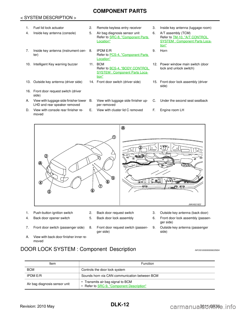
1. Fuel lid lock actuator 2. Remote keyless entry receiver 3. Inside key antenna (luggage room)
4. Inside key antenna (console) 5. Air bag diagnosis sensor unit Refer to SRC-8, "
Component Parts
Location"
6. A/T assembly (TCM)
Refer to TM-10, "
A/T CONTROL
SYSTEM : Component Parts Loca-
tion"
7. Inside key antenna (instrument cen-
ter) 8. IPDM E/R
Refer to PCS-4, "
Component Parts
Location"
9. Horn
10. Intelligent Key warning buzzer 11. BCM Refer to BCS-4, "
BODY CONTROL
SYSTEM : Component Parts Loca-
tion"
12. Power window main switch (door
lock and unlock switch)
13. Outside key antenna (driver side) 14. Front door switch (driver side) 15. Front door lock assembly (driver side)
16. Front door request switch (driver side)
A. View with luggage side finisher lower LHD and rear speaker removed B. View with luggage side finisher up-
per removed C. Under the second seat seatback
D. View with console rear finisher re- moved E. View with cluster lid C removed F. Engine room LH
1. Push-button ignition switch 2. Back door request switch 3. Outside key antenna (back door)
4. Back door opener switch 5. Back door lock assembly 6. Front door lock assembly (passen- ger side)
7. Front door switch (passenger side) 8. Front door request switch (passen- ger side)9. Outside key antenna (passenger
side)
A. View with back door finisher inner re- moved
JMKIA5218ZZ
Item Function
BCM Controls the door lock system
IPDM E/R Sounds horn via CAN communication between BCM
Air bag diagnosis sensor unit Transmits air bag signal to BCM
Refer to
SRC-9, "
Component Description"
Revision: 2010 May2011 QX56
Page 1549 of 5598
COMPONENT PARTSDLK-13
< SYSTEM DESCRIPTION >
C
DE
F
G H
I
J
L
M A
B
DLK
N
O P
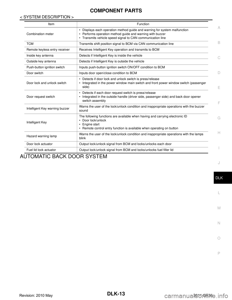
AUTOMATIC BACK DOOR SYSTEM
Combination meter Displays each operation method guide and warning for system malfunction
Performs operation method guide and warning with buzzer
Transmits vehicle speed signal to CAN communication line
TCM Transmits shift position signal to BCM via CAN communication line
Remote keyless entry receiver Receives Intelligent Key operation and transmits to BCM
Inside key antenna Detects if Intelligent Key is inside the vehicle
Outside key antenna Detects if Intelligent Key is outside the vehicle
Push-button ignition switch Inputs push-button ignition switch ON/OFF condition to BCM
Door switch Inputs door open/close condition to BCM
Door lock and unlock switch Detects if door lock and unlock switch is press/release
Integrated in the power window main switch and front power window switch (passenger
side)
Door request switch Detects if each door request switch is press/release
Integrated in the outside handle (driver side, passenger side) and back door opener
switch assembly
Intelligent Key warning buzzer Warns the user of the lock/unlock condition and inappropriate operations with the buzzer
sound
Intelligent Key The following functions are available when having and carrying electronic ID
Door lock/unlock
Engine start
Remote control entry function is available when operating on button
Hazard warning lamp Warns the user of the lock/unlock condition and inappropriate operations with the lamps
blink
Door lock actuator Output lock/unlock signal from BCM and locks/unlocks each door
Fuel lid lock actuator Output lock/unlock signal from BCM and locks/unlocks fuel filler lid Item Function
Revision: 2010 May2011 QX56
Page 1552 of 5598

DLK-16
< SYSTEM DESCRIPTION >
SYSTEM (POWER DOOR LOCK SYSTEM)
SYSTEM (POWER DOOR LOCK SYSTEM)
System DiagramINFOID:0000000006225837
System DescriptionINFOID:0000000006225838
DOOR LOCK FUNCTION
Door Lock and Unlock Switch
The door lock and unlock switch (driver side) is build into power window main switch.
The door lock and unlock switch (passenger side) is build into front power window switch (passenger side).
Interlocked with the locking operation of door lock and unlock switch, door lock actuators of all doors and
fuel lid lock actuator are locked.
Interlocked with the unlocking operation of door lock and unlock switch, door lock actuators of all doors actu-
ator and fuel lid lock actuator are unlocked.
Door Key Cylinder Switch
With the mechanical key inserted in the door key cylinder on driver side, turning it to lock position, locks door
lock actuator of all doors and fuel lid lock actuator.
With the mechanical key inserted in the door key cylinder on driver side, turning it to unlock position once
unlocks the driver side door, turning it to unlock posit ion again within 60 seconds after the first unlock opera-
tion unlocks all of the other doors actuator and fuel lid lock actuator. (SELECTIVE UNLOCK OPERATION)
Selective unlock operation mode can be changed using CONSULT-III.
Refer to DLK-39, "
DOOR LOCK : CONSULT-III Function (BCM - DOOR LOCK)".
DOOR KEY CYLINDER SWITCH POWER WINDOW FUNCTION
Driver side door key cylinder LOCK/UNLOCK oper ation can activate power window. Refer to PWC-8, "System
Description".
IGNITION POSITION WARNING FUNCTION
When door lock and unlock switch are operated while dr iver side door is open and ignition position is ACC or
ON, door locks once but immediately unlocks.
INTERIOR ROOM LAMP CONTROL FUNCTION
Interior room lamp is controlled according to door lock/unlock state, refer to INL-6, "INTERIOR ROOM LAMP
CONTROL SYSTEM : System Description".
AUTOMATIC DOOR LOCK/UNLOCK FUNCTION (LOCK OPERATION)
The interlock door lock function is the function that locks all doors linked with the vehicle speed or shift posi-
tion. It has 2 types as per the following items.
Vehicle Speed Sensing Auto Door Lock
All doors are locked when the vehicle speed reaches 24 km/h (15 MPH) or more.
BCM outputs the lock signal to all door lock actuators when it detects that the ignition switch is turned ON, all
doors are closed and the vehicle speed received from the combination meter via CAN communication
becomes 24 km/h (15 MPH) or more.
JMKIA5278GB
Revision: 2010 May2011 QX56