instrument cluster INFINITI QX56 2011 Factory Service Manual
[x] Cancel search | Manufacturer: INFINITI, Model Year: 2011, Model line: QX56, Model: INFINITI QX56 2011Pages: 5598, PDF Size: 94.53 MB
Page 735 of 5598

BRM-60
< SERVICE DATA AND SPECIFICATIONS (SDS)
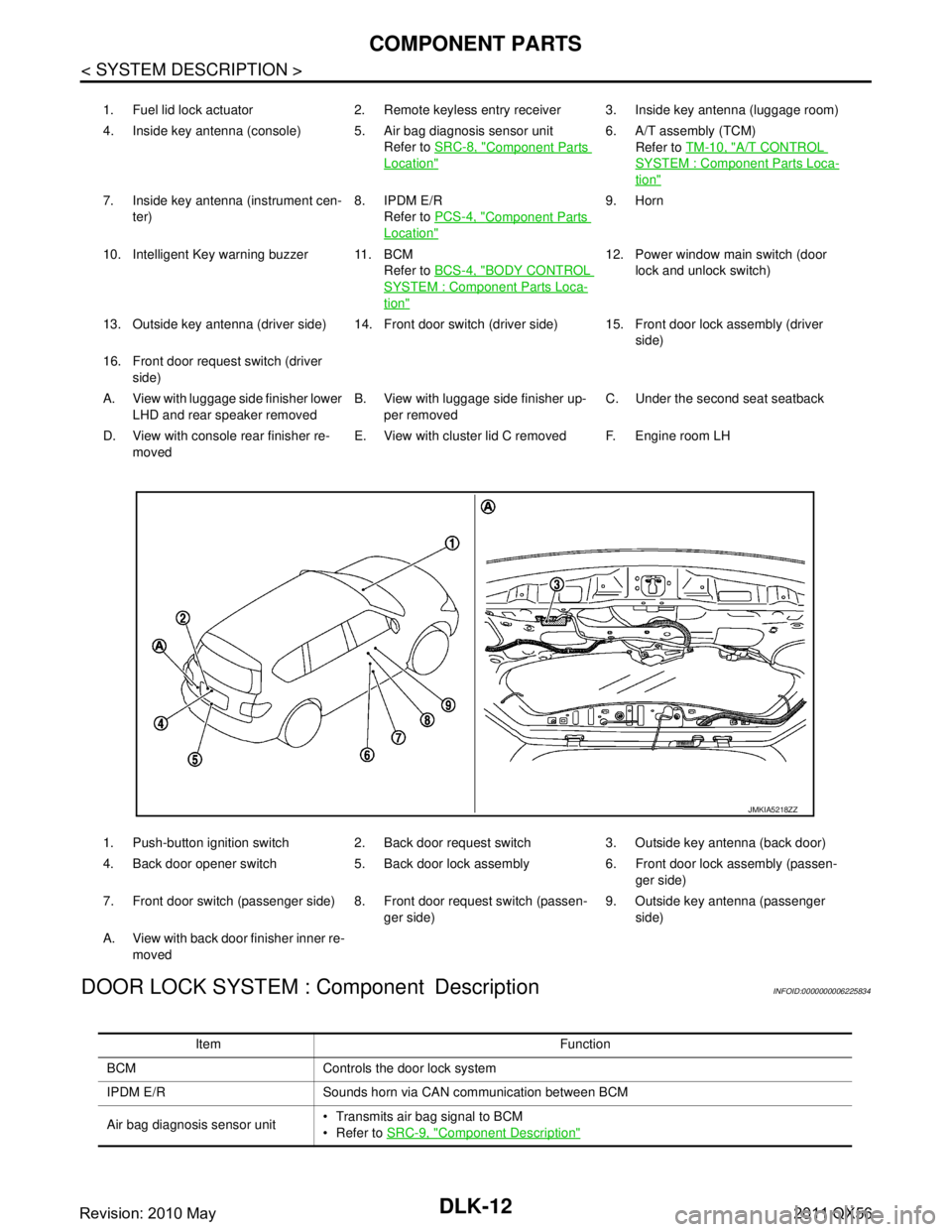
LOCATION OF PLASTIC PARTS
Component Material Component Material
1Map lamp Lens PC 7 Center console PP
Housing PP 8 Glove box PP
2 Front pillar garnish PP 9 Instrument panelCore PP
3 Center pillar garnish PP Skin TPU
4Personal lamp Lens PC 10 Cluster lid C PC + ABS
Housing PP 11 Cluster lid D PC + ABS
5 Rear pillar finisher PP 12 Cluster lid A ABS
6 Back pillar garnish PP
JSKIA1905ZZ
Revision: 2010 May2011 QX56
Page 1548 of 5598

DLK-12
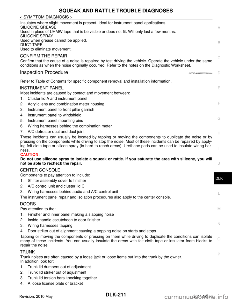
< SYSTEM DESCRIPTION >
COMPONENT PARTS
DOOR LOCK SYSTEM : Component Description
INFOID:0000000006225834
1. Fuel lid lock actuator 2. Remote keyless entry receiver 3. Inside key antenna (luggage room)
4. Inside key antenna (console) 5. Air bag diagnosis sensor unit Refer to SRC-8, "
Component Parts
Location"
6. A/T assembly (TCM)
Refer to TM-10, "
A/T CONTROL
SYSTEM : Component Parts Loca-
tion"
7. Inside key antenna (instrument cen-
ter) 8. IPDM E/R
Refer to PCS-4, "
Component Parts
Location"
9. Horn
10. Intelligent Key warning buzzer 11. BCM Refer to BCS-4, "
BODY CONTROL
SYSTEM : Component Parts Loca-
tion"
12. Power window main switch (door
lock and unlock switch)
13. Outside key antenna (driver side) 14. Front door switch (driver side) 15. Front door lock assembly (driver side)
16. Front door request switch (driver side)
A. View with luggage side finisher lower LHD and rear speaker removed B. View with luggage side finisher up-
per removed C. Under the second seat seatback
D. View with console rear finisher re- moved E. View with cluster lid C removed F. Engine room LH
1. Push-button ignition switch 2. Back door request switch 3. Outside key antenna (back door)
4. Back door opener switch 5. Back door lock assembly 6. Front door lock assembly (passen- ger side)
7. Front door switch (passenger side) 8. Front door request switch (passen- ger side)9. Outside key antenna (passenger
side)
A. View with back door finisher inner re- moved
JMKIA5218ZZ
Item Function
BCM Controls the door lock system
IPDM E/R Sounds horn via CAN communication between BCM
Air bag diagnosis sensor unit Transmits air bag signal to BCM
Refer to
SRC-9, "
Component Description"
Revision: 2010 May2011 QX56
Page 1747 of 5598

SQUEAK AND RATTLE TROUBLE DIAGNOSESDLK-211
< SYMPTOM DIAGNOSIS >
C
DE
F
G H
I
J
L
M A
B
DLK
N
O P
Insulates where slight movement is present. Ideal for instrument panel applications.
SILICONE GREASE
Used in place of UHMW tape that is be visible or does not fit. Will only last a few months.
SILICONE SPRAY
Used when grease cannot be applied.
DUCT TAPE
Used to eliminate movement.
CONFIRM THE REPAIR
Confirm that the cause of a noise is repaired by test driving the vehicle. Operate the vehicle under the same
conditions as when the noise originally occurred. Refer to the notes on the Diagnostic Worksheet.
Inspection ProcedureINFOID:0000000006226060
Refer to Table of Contents for specific component removal and installation information.
INSTRUMENT PANEL
Most incidents are caused by contact and movement between:
1. Cluster lid A and instrument panel
2. Acrylic lens and combination meter housing
3. Instrument panel to front pillar garnish
4. Instrument panel to windshield
5. Instrument panel mounting pins
6. Wiring harnesses behind the combination meter
7. A/C defroster duct and duct joint
These incidents can usually be located by tapping or moving the components to duplicate the noise or by
pressing on the components while driving to stop the noi se. Most of these incidents can be repaired by apply-
ing felt cloth tape or silicon spray (in hard to reach areas). Urethane pads can be used to insulate wiring har-
ness.
CAUTION:
Do not use silicone spray to isolate a squeak or ra ttle. If you saturate the area with silicone, you will
not be able to recheck the repair.
CENTER CONSOLE
Components to pay attention to include:
1. Shifter assembly cover to finisher
2. A/C control unit and cluster lid C
3. Wiring harnesses behind audio and A/C control unit
The instrument panel repair and isolation pr ocedures also apply to the center console.
DOORS
Pay attention to the:
1. Finisher and inner panel making a slapping noise
2. Inside handle escutcheon to door finisher
3. Wiring harnesses tapping
4. Door striker out of alignment causing a popping noise on starts and stops
Tapping or moving the components or pressing on them while driving to duplicate the conditions can isolate
many of these incidents. You can usually insulate the areas with felt cloth tape or insulator foam blocks to
repair the noise.
TRUNK
Trunk noises are often caused by a loose jack or loose items put into the trunk by the owner.
In addition look for:
1. Trunk lid dumpers out of adjustment
2. Trunk lid striker out of adjustment
3. Trunk lid torsion bars knocking together
4. A loose license plate or bracket
Revision: 2010 May2011 QX56
Page 1792 of 5598

DLK-256
< REMOVAL AND INSTALLATION >
INSIDE KEY ANTENNA
INSIDE KEY ANTENNA
INSTRUMENT CENTER
INSTRUMENT CENTER : Removal and InstallationINFOID:0000000006226119
REMOVAL
1. Remove the cluster lid C. Refer to IP-14, "Removal and Installation".
2. Remove the inside key antenna (instrument cente r) mounting screw, and then remove inside key antenna
(instrument center).
INSTALLATION
Install in the reverse order of removal.
CONSOLE
CONSOLE : Removal and InstallationINFOID:0000000006226120
REMOVAL
1. Remove the console rear finisher. Refer to IP-29, "Removal and Installation".
2. Remove the inside key antenna (console) mounting screw, and then remove inside key antenna (con- sole).
INSTALLATION
Install in the reverse order of removal.
LUGGAGE ROOM
LUGGAGE ROOM : Removal and InstallationINFOID:0000000006226121
REMOVAL
1. Remove the second seat seatback. Refer to SE-126, "SEATBACK : Disassembly and Assembly".
2. Remove the inside key antenna (luggage room) mounting clip, and then remove inside ke\
y antenna (lug- gage room).
INSTALLATION
Install in the reverse order of removal.
Revision: 2010 May2011 QX56
Page 2863 of 5598

EXT-8
< SYMPTOM DIAGNOSIS >
SQUEAK AND RATTLE TROUBLE DIAGNOSES
Used to insulate where movement does not occur. Ideal for instrument panel applications.
68370-4B000: 15 ×25 mm (0.591 ×0.984 in) pad
68239-13E00: 5 mm (0.197 in) wide tape roll
The following materials, not found in the kit, can also be used to repair squeaks and rattles.
UHMW (TEFLON) TAPE
Insulates where slight movement is present. Ideal for instrument panel applications.
SILICONE GREASE
Used in place of UHMW tape that is visible or does not fit. Only lasts a few months.
SILICONE SPRAY
Used when grease cannot be applied.
DUCT TAPE
Used to eliminate movement.
CONFIRM THE REPAIR
After repair is complete, test drive the vehicle to confir m that the cause of noise is repaired by test driving the
vehicle. Operate the vehicle under the same conditions as when the noise originally occurred. Refer to the
notes on the Diagnostic Worksheet.
Inspection ProcedureINFOID:0000000006367801
Refer to Table of Contents for specific component removal and installation information.
INSTRUMENT PANEL
Most incidents are caused by contact and movement between:
1. The cluster lid A and instrument panel
2. Acrylic lens and combination meter housing
3. Instrument panel to front pillar garnish
4. Instrument panel to windshield
5. Instrument panel mounting pins
6. Wiring harnesses behind the combination meter
7. A/C defroster duct and duct joint
These incidents can usually be located by tapping or moving the components to duplicate the noise or by
pressing on the components while driving to stop the noise. Most of these incidents can be repaired by
applying felt cloth tape or silicon spray (in hard to reach areas). Urethane pads can be used to insulate
wiring harness.
CAUTION:
Never use silicone spray to isolate a squeak or ra ttle. If the area is saturated with silicone, the
recheck of repair becomes impossible.
CENTER CONSOLE
Components to check include:
1. Shifter assembly cover to finisher
2. A/C control unit and cluster lid C
3. Wiring harnesses behind audio and A/C control unit
The instrument panel repair and isolation pr ocedures also apply to the center console.
DOORS
Check the following items:
1. Finisher and inner panel making a slapping noise
2. Inside handle escutcheon connection to door finisher
3. Wiring harnesses tapping
4. Door striker out of alignment causing a popping noise on starts and stops
Tapping, moving the components, or pressing on them wh ile driving to duplicate the conditions can isolate
many of these incidents. The areas can usually be insula ted with felt cloth tape or insulator foam blocks from
the NISSAN Squeak and Rattle Kit (J-43980) to repair the noise.
TRUNK
Trunk noises are often caused by a loose jack or loose items put into the trunk by the customer.
In addition check for the following items:
Revision: 2010 May2011 QX56
Page 3036 of 5598

SQUEAK AND RATTLE TROUBLE DIAGNOSESGW-7
< SYMPTOM DIAGNOSIS >
C
DE
F
G H
I
J
L
M A
B
GW
N
O P
68370-4B000: 15 ×25 mm (0.59 ×0.98 in) pad/68239-13E00: 5 mm (0.20 in) wide tape roll
The following materials, not found in the kit, can also be used to repair squeaks and rattles.
UHMW (TEFLON) TAPE
Insulates where slight movement is present. Ideal for instrument panel applications.
SILICONE GREASE
Used in place of UHMW tape that will be visible or not fit. Will only last a few months.
SILICONE SPRAY
Use when grease cannot be applied.
DUCT TAPE
Use to eliminate movement.
CONFIRM THE REPAIR
Confirm that the cause of a noise is repaired by test driving the vehicle. Operate the vehicle under the same
conditions as when the noise originally occurred. Refer to the notes on the Diagnostic Worksheet.
Inspection ProcedureINFOID:0000000006108036
Refer to Table of Contents for specific component removal and installationinformation.
INSTRUMENT PANEL
Most incidents are caused by contact and movement between:
1. The cluster lid A and instrument panel
2. Acrylic lens and combination meter housing
3. Instrument panel to front pillar garnish
4. Instrument panel to windshield
5. Instrument panel mounting pins
6. Wiring harnesses behind the combination meter
7. A/C defroster duct and duct joint
These incidents can usually be located by tapping or moving the components to duplicate the noise or by
pressing on the components while driving to stop the noise. Most of these incidents can be repaired by
applying felt cloth tape or silicon spray (in hard to reach areas). Urethane pads can be used to insulate
wiring harness.
CAUTION:
Do not use silicone spray to isolate a squeak or rattle. If you saturatethe area with silicone, you
will not be able to recheck the repair.
CENTER CONSOLE
Components to pay attention to include:
1. Shifter assembly cover to finisher
2. A/C control unit and cluster lid C
3. Wiring harnesses behind audio and A/C control unit
The instrument panel repair and isolation procedures also apply to thecenter console.
DOORS
Pay attention to the:
1. Finisher and inner panel making a slapping noise
2. Inside handle escutcheon to door finisher
3. Wiring harnesses tapping
4. Door striker out of alignment causing a popping noise on startsand stops
Tapping or moving the components or pressing on them while driving to duplicate the conditions can isolate
many of these incidents. You can usually insulate the ar eas with felt cloth tape or insulator foam blocks from
the Nissan Squeak and Rattle Kit (J-43980) to repair the noise.
TRUNK
Trunk noises are often caused by a loose jack or loose items put intothe trunk by the owner.
In addition look for:
1. Trunk lid dumpers out of adjustment
2. Trunk lid striker out of adjustment
Revision: 2010 May2011 QX56
Page 3358 of 5598

SQUEAK AND RATTLE TROUBLE DIAGNOSESINT-9
< SYMPTOM DIAGNOSIS >
C
DE
F
G H
I
K L
M A
B
INT
N
O P
Used to insulate where movement does not occur. Ideal for instrument panel applications.
68370-4B000: 15 ×25 mm (0.591 ×0.984 in) pad
68239-13E00: 5 mm (0.197 in) wide tape roll
The following materials, not found in the kit, can also be used to repair squeaks and rattles.
UHMW (TEFLON) TAPE
Insulates where slight movement is present. Ideal for instrument panel applications.
SILICONE GREASE
Used in place of UHMW tape that is visible or does not fit. Only lasts a few months.
SILICONE SPRAY
Used when grease cannot be applied.
DUCT TAPE
Used to eliminate movement.
CONFIRM THE REPAIR
After repair is complete, test drive the vehicle to confi rm that the cause of noise is repaired by test driving the
vehicle. Operate the vehicle under the same conditions as when the noise originally occurred. Refer to the
notes on the Diagnostic Worksheet.
Inspection ProcedureINFOID:0000000006220270
Refer to Table of Contents for specific component removal and installation information.
INSTRUMENT PANEL
Most incidents are caused by contact and movement between:
1. The cluster lid A and instrument panel
2. Acrylic lens and combination meter housing
3. Instrument panel to front pillar garnish
4. Instrument panel to windshield
5. Instrument panel mounting pins
6. Wiring harnesses behind the combination meter
7. A/C defroster duct and duct joint
These incidents can usually be located by tapping or moving the components to duplicate the noise or by
pressing on the components while driving to stop the noise. Most of these incidents can be repaired by
applying felt cloth tape or silicon spray (in hard to reach areas). Urethane pads can be used to insulate
wiring harness.
CAUTION:
Never use silicone spray to isolate a squeak or ra ttle. If the area is saturated with silicone, the
recheck of repair becomes impossible.
CENTER CONSOLE
Components to check include:
1. Shifter assembly cover to finisher
2. A/C control unit and cluster lid C
3. Wiring harnesses behind audio and A/C control unit
The instrument panel repair and isolation pr ocedures also apply to the center console.
DOORS
Check the following items:
1. Finisher and inner panel making a slapping noise
2. Inside handle escutcheon connection to door finisher
3. Wiring harnesses tapping
4. Door striker out of alignment causing a popping noise on starts and stops
Tapping, moving the components, or pressing on them while driving to duplicate the conditions can isolate
many of these incidents. The areas can usually be insula ted with felt cloth tape or insulator foam blocks from
the NISSAN Squeak and Rattle Kit (J-43980) to repair the noise.
TRUNK
Trunk noises are often caused by a loose jack or loose items put into the trunk by the customer.
In addition check for the following items:
Revision: 2010 May2011 QX56
Page 3399 of 5598

SQUEAK AND RATTLE TROUBLE DIAGNOSESIP-9
< SYMPTOM DIAGNOSIS >
C
DE
F
G H
I
K L
M A
B
IP
N
O P
Used to insulate where movement does not occur. Ideal for instrument panel applications.
68370-4B000: 15 ×25 mm (0.591 ×0.984 in) pad
68239-13E00: 5 mm (0.197 in) wide tape roll
The following materials, not found in the kit, can also be used to repair squeaks and rattles.
UHMW (TEFLON) TAPE
Insulates where slight movement is present. Ideal for instrument panel applications.
SILICONE GREASE
Used in place of UHMW tape that is visible or does not fit. Only lasts a few months.
SILICONE SPRAY
Used when grease cannot be applied.
DUCT TAPE
Used to eliminate movement.
CONFIRM THE REPAIR
After repair is complete, test drive the vehicle to confi rm that the cause of noise is repaired by test driving the
vehicle. Operate the vehicle under the same conditions as when the noise originally occurred. Refer to the
notes on the Diagnostic Worksheet.
Inspection ProcedureINFOID:0000000006425524
Refer to Table of Contents for specific component removal and installation information.
INSTRUMENT PANEL
Most incidents are caused by contact and movement between:
1. The cluster lid A and instrument panel
2. Acrylic lens and combination meter housing
3. Instrument panel to front pillar garnish
4. Instrument panel to windshield
5. Instrument panel mounting pins
6. Wiring harnesses behind the combination meter
7. A/C defroster duct and duct joint
These incidents can usually be located by tapping or moving the components to duplicate the noise or by
pressing on the components while driving to stop the noise. Most of these incidents can be repaired by
applying felt cloth tape or silicon spray (in hard to reach areas). Urethane pads can be used to insulate
wiring harness.
CAUTION:
Never use silicone spray to isolate a squeak or ra ttle. If the area is saturated with silicone, the
recheck of repair becomes impossible.
CENTER CONSOLE
Components to check include:
1. Shifter assembly cover to finisher
2. A/C control unit and cluster lid C
3. Wiring harnesses behind audio and A/C control unit
The instrument panel repair and isolation pr ocedures also apply to the center console.
DOORS
Check the following items:
1. Finisher and inner panel making a slapping noise
2. Inside handle escutcheon connection to door finisher
3. Wiring harnesses tapping
4. Door striker out of alignment causing a popping noise on starts and stops
Tapping, moving the components, or pressing on them while driving to duplicate the conditions can isolate
many of these incidents. The areas can usually be insula ted with felt cloth tape or insulator foam blocks from
the NISSAN Squeak and Rattle Kit (J-43980) to repair the noise.
TRUNK
Trunk noises are often caused by a loose jack or loose items put into the trunk by the customer.
In addition check for the following items:
Revision: 2010 May2011 QX56
Page 3404 of 5598

IP-14
< REMOVAL AND INSTALLATION >
INSTRUMENT PANEL ASSEMBLY
Removal and Installation
INFOID:0000000006113098
WORK STEP
When removing instrument panel assembly, combination meter, front display unit, AV control unit, instrument
finisher A, instrument fini sher B, and center console assembly take st eps as per the order shown in the follow-
ing chart.
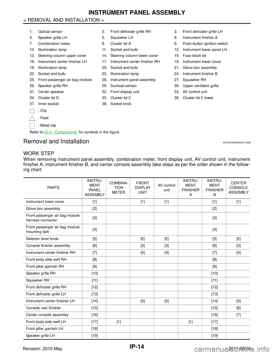
1. Optical sensor 2. Front defroster grille RH 3. Front defroster grille LH
4. Speaker grille LH 5. Squawker LH 6. Instrument finisher A
7. Combination meter 8. Cluster lid A 9. Push-button ignition switch
10. Illumination lamp 11. Socket and bulb 12. Instrument lower panel LH
13. Steering column upper cover 14. Steering column lower cover 15. Fuse block lid
16. Instrument center finisher LH 17. Instrument center finisher RH 18. Instrument lower cover
19. Illumination lamp 20. Socket and bulb 21. Glove box assembly
22. Socket and bulb 23. Illumination lamp 24. Instrument finisher B
25. Front passenger air bag module 26. Instrument panel assembly 27. Squawker RH
28. Speaker grille RH 29. Sunload sensor 30. Upper ventilator grille
31. Center speaker 32. Front display unit 33. AV control unit
34. Cluster lid D 35. Cluster lid C 36. Cluster lid C lower
37. Inner socket 38. Socket knob
: Clip
: Pawl
: Metal clip
Refer to GI-4, "
Components" for symbols in the figure.
PA R T S INSTRU-
MENT
PA N E L
ASSEMBLY COMBINA-
TION
METER FRONT
DISPLAY
UNIT AV c o n t r o l
unit INSTRU-
MENT
FINISHER A INSTRU-
MENT
FINISHER B CENTER
CONSOLE
ASSEMBLY
Instrument lower cover [1] [1] [1] [1] [1]
Glove box assembly [2] [2]
Front passenger air bag module
harness connector [3] [3]
Front passenger air bag module
mounting bolt [4] [4]
Selector lever knob [5] [2] [2] [5] [2]
Console finisher assembly [6] [3] [3] [6] [3]
Instrument center finisher RH [7] [4] [4] [7] [4]
Front body side welt RH [8] [8]
Front pillar garnish RH [9] [9]
Speaker grille RH [10] [10]
Squawker RH [11] [11]
Front defroster grille RH [12] [12]
Front defroster grille LH [13] [13]
Instrument center finisher LH [14] [5] [5] [14] [5]
Console rear finisher [15] [15] [6]
Center console assembly [16] [16] [7]
Front body side welt LH [17] [1] [1] [17]
Front pillar garnish LH [18] [18]
Speaker grille LH [19] [19]
Revision: 2010 May2011 QX56
Page 3405 of 5598
![INFINITI QX56 2011 Factory Service Manual
INSTRUMENT PANEL ASSEMBLYIP-15
< REMOVAL AND INSTALLATION >
C
DE
F
G H
I
K L
M A
B
IP
N
O P
[ ]:Number indicates step in removal procedures.
WARNING:
Before servicing, turn igni tion switch OFF, disc INFINITI QX56 2011 Factory Service Manual
INSTRUMENT PANEL ASSEMBLYIP-15
< REMOVAL AND INSTALLATION >
C
DE
F
G H
I
K L
M A
B
IP
N
O P
[ ]:Number indicates step in removal procedures.
WARNING:
Before servicing, turn igni tion switch OFF, disc](/img/42/57033/w960_57033-3404.png)
INSTRUMENT PANEL ASSEMBLYIP-15
< REMOVAL AND INSTALLATION >
C
DE
F
G H
I
K L
M A
B
IP
N
O P
[ ]:Number indicates step in removal procedures.
WARNING:
Before servicing, turn igni tion switch OFF, disconnect battery ne gative terminal, and wait 3 minutes or
more.
CAUTION:
When removing, always use a remover tool that is made of plastic.
REMOVAL
1. Remove instrument lower cover.
1. Pull disengaged pawls downward.
2. Pull back instrument lower cover.
3. Disconnect harness connectors.
Squawker LH [20] [20]
Instrument lower panel LH [21] [2] [2] [21]
Disconnect meter control switch
harness connector [22] [3] [3] [22]
Driver air bag module [23] [23]
Steering wheel [24] [24]
Steering column cover [25] [25]
Combination switch [26] [26]
Spiral cable [27] [27]
Cluster lid A [28] [4] [4] [28]
Combination meter [29] [5] [29]
Instrument finisher A [5]
Upper ventilator grille [30] [30]
Center speaker [31] [31]
Cluster lid C [32] [6] [6] [32]
Cluster lid C lower [33] [7] [33]
AV control unit [34] [8] [34]
Cluster lid D [35] [7] [35]
Front display unit [36] [8] [36]
instrument panel assembly
mounting screws and bolts [37] [37]
Squawker LH harness clip [38] [38]
Instrument panel assembly [39] [39]
Instrument finisher B [40]
PA R T S
INSTRU-
MENT
PA N E L
ASSEMBLY COMBINA-
TION
METER FRONT
DISPLAY UNIT AV c o n t r o l
unit INSTRU-
MENT
FINISHER A INSTRU-
MENT
FINISHER B CENTER
CONSOLE
ASSEMBLY
: Pawl
JMJIA3828ZZ
Revision: 2010 May2011 QX56