refrigerant type INFINITI QX56 2011 Factory Service Manual
[x] Cancel search | Manufacturer: INFINITI, Model Year: 2011, Model line: QX56, Model: INFINITI QX56 2011Pages: 5598, PDF Size: 94.53 MB
Page 3061 of 5598

PRECAUTIONSHA-5
< PRECAUTION >
C
DE
F
G H
J
K L
M A
B
HA
N
O P
- Never allow lubricant (A/C System Oil Type R) to come in contact with styrene foam parts. Damage
may result.
REFRIGERANT CONNECTION
A new type refrigerant connection has been introduced to a ll refrigerant lines except the following location.
Expansion valve to evaporator
Refrigerant pressure sensor to liquid tank
WARNING:
Check that all refrigerant is discharged into the recycling equipment and the pressure in the system is
less than atmospheric pressure. Then gradually loo sen the discharge side hose fitting and remove it.
CAUTION:
Observe the following when replacing or cleaning refrigerant cycle components.
Store it in the same way at it is when mounted on the car when the compressor is removed. Failure
to do so will cause lubricant to enter the low-pressure chamber.
Use always a torque wrench and a b ack-up wrench when connecting tubes.
Plug immediately all openings to prevent entry of dust and mois ture after disconnecting tubes.
Connect the pipes at the final stag e of the operation when installing an air conditioner in the vehicle.
Never remove the seal caps of pipes and other compon ents until just before required for connection.
Allow components stored in cool areas to warm to working area temperature before removing seal
caps. This prevents condensation from forming inside A/C components.
Remove thoroughly moisture from the refriger ation system before charging the refrigerant.
Replace always used O-rings.
Apply lubricant to circle of th e O-rings shown in illustration when connecting tube. Be careful not to
apply lubricant to threaded portion.
O-ring must be closely attached to the groove portion of tube.
Be careful not to damage O-ring and tube when replacing the O-ring.
Connect tube until a click can be heard. Then tighten the nut or bolt by hand. Check that the O-ring is
installed to tube correctly.
Perform leakage test and make sure that there is no leakage from connections after connecting line.
Disconnect that line and replace the O-ring when the refrigerant leaking point is found. Then tighten
connections of seal seat to the specified torque.
COMPRESSOR
CAUTION:
Plug all openings to prevent moisture and foreign matter from entering.
Store it in the same way at it is when moun ted on the car when the compressor is removed.
Follow “MAINTENANCE OF LUBRICANT LEVEL IN CO MPRESSOR” exactly when replacing or repair-
ing compressor. Refer to HA-22, "
Description".
Keep friction surfaces between clutch and pulley cl ean. Wipe it off by using a clean waste cloth
moistened with thinner if the surface is contaminated with lubricant.
Name A/C System Oil Type S
RHA861F
Revision: 2010 May2011 QX56
Page 3065 of 5598

PREPARATIONHA-9
< PREPARATION >
C
DE
F
G H
J
K L
M A
B
HA
N
O P
PREPARATION
PREPARATION
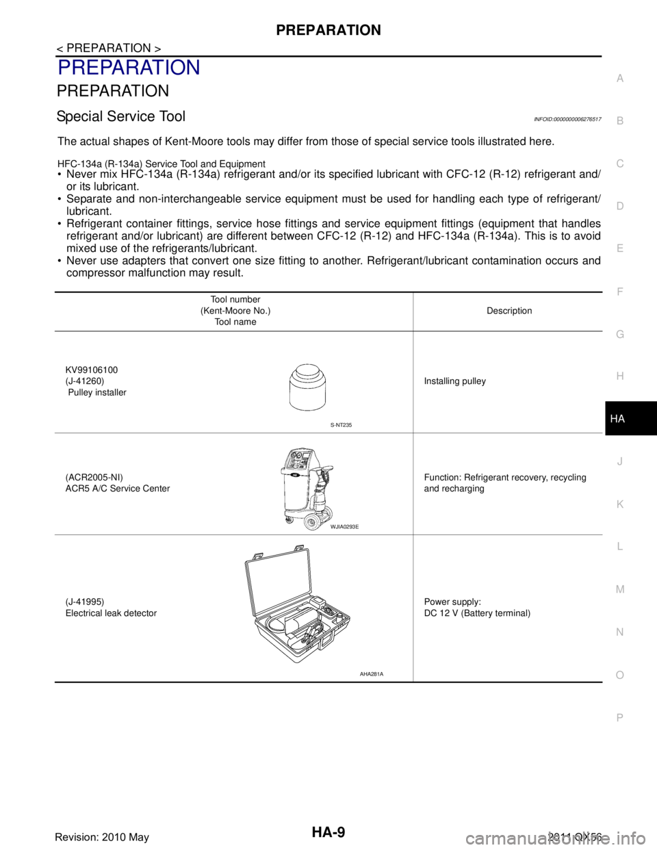
Special Service ToolINFOID:0000000006276517
The actual shapes of Kent-Moore tools may differ fr om those of special service tools illustrated here.
HFC-134a (R-134a) Service Tool and Equipment
Never mix HFC-134a (R-134a) refrigerant and/or its spec ified lubricant with CFC-12 (R-12) refrigerant and/
or its lubricant.
Separate and non-interchangeable service equipment must be used for handling each type of refrigerant/
lubricant.
Refrigerant container fittings, service hose fittings and service equipment fittings (equipment that handles
refrigerant and/or lubricant) are different between CF C-12 (R-12) and HFC-134a (R-134a). This is to avoid
mixed use of the refrigerants/lubricant.
Never use adapters that convert one size fitting to another. Refrigerant/lubricant contamination occurs and
compressor malfunction may result.
Tool number
(Kent-Moore No.) Tool name Description
KV99106100
(J-41260)
Pulley installer Installing pulley
(ACR2005-NI)
ACR5 A/C Se rvice Center Function: Refrigerant recovery, recycling
and recharging
(J-41995)
Electrical leak detector Power supply:
DC 12 V (Battery terminal)
S-NT235
WJIA0293E
AHA281A
Revision: 2010 May2011 QX56
Page 3068 of 5598

HA-12
< PREPARATION >
PREPARATION
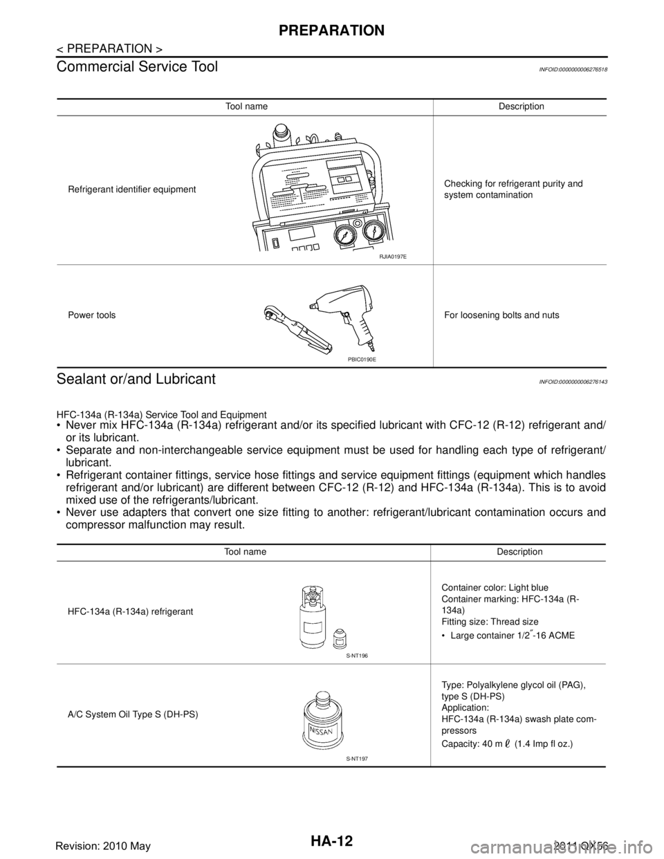
Commercial Service Tool
INFOID:0000000006276518
Sealant or/and LubricantINFOID:0000000006276143
HFC-134a (R-134a) Service Tool and Equipment
Never mix HFC-134a (R-134a) refrigerant and/or its s pecified lubricant with CFC-12 (R-12) refrigerant and/
or its lubricant.
Separate and non-interchangeable service equipment must be used for handling each type of refrigerant/ lubricant.
Refrigerant container fittings, service hose fittings and service equipment fittings (equipment which handles
refrigerant and/or lubricant) are different between CF C-12 (R-12) and HFC-134a (R-134a). This is to avoid
mixed use of the refrigerants/lubricant.
Never use adapters that convert one size fitting to another: refrigerant/lubricant contamination occurs and
compressor malfunction may result.
Tool name Description
Refrigerant identifier equipment Checking for refrigerant purity and
system contamination
Power tools For loosening bolts and nuts
RJIA0197E
PBIC0190E
Tool name Description
HFC-134a (R-134a) refrigerant Container color: Light blue
Container marking: HFC-134a (R-
134a)
Fitting size: Thread size
Large container 1/2
″-16 ACME
A/C System Oil Type S (DH-PS) Type: Polyalkylene glycol oil (PAG),
type S (DH-PS)
Application:
HFC-134a (R-134a) swash plate com-
pressors
Capacity: 40 m (1.4 Imp fl oz.)
S-NT196
S-NT197
Revision: 2010 May2011 QX56
Page 3078 of 5598

HA-22
< BASIC INSPECTION >
LUBRICANT
LUBRICANT
DescriptionINFOID:0000000006276153
MAINTENANCE OF LUBRICANT LEVEL
The compressor lubricant is circulating in the system together with the refrigerant. It is necessary to fill com-
pressor with lubricant when replacing A/C system pa rts or when a large amount of refrigerant leakage is
detected. It is important to always maintain lubricant level within the specified level. Otherwise, the following
conditions may occur.
Insufficient lubricant amount: Stuck compressor
Excessive lubricant amount: Insufficient cooling (caused by insufficient heat exchange)
InspectionINFOID:0000000006276154
If a compressor is malfunctioning (internal noise, insufficient cooling), check the compressor oil.
1.COMPRESSOR OIL JUDGMENT
1. Remove the compressor. Refer to HA-30, "
Exploded View".
2. Sample a compressor oil and judge on the figure.
Judgement result 1>>Replace compressor only.
Judgement result 2>>Replace compressor and liquid tank.
Perform Lubricant Return OperationINFOID:0000000006276155
CAUTION:
If a large amount of refrigerant or lubricant leakag e is detected, never perform lubricant return opera-
tion.
1. Start the engine and set to the following conditions.
Engine speed: Idling to 1,200 rpm
A/C switch: ON
Fan speed: Maximum speed set
Intake door position: Recirculation
Temperature setting: Full cold
2. Perform lubricant return operation for approximately 10 minutes.
3. Stop the engine.
4. Lubricant return operation is complete.
Lubricant Adjusting Procedure for Comp onents Replacement Except Compressor
INFOID:0000000006276156
Fill with lubricant for the amount that is calculated according to the following conditions.
Example: Lubricant amount to be added when replacing evapor ator and liquid tank [m (Imp fl oz.)] = 35 (1.2)
+ 20 (0.7) + 5 (0.2) + α
Name A/C System Oil Type S
JSIIA0927GB
Revision: 2010 May2011 QX56
Page 3106 of 5598

HA-50
< SERVICE DATA AND SPECIFICATIONS (SDS)
SERVICE DATA AND SPECIFICATIONS (SDS)
SERVICE DATA AND SPECIFICATIONS (SDS)
SERVICE DATA AND SPECIFICATIONS (SDS)
CompressorINFOID:0000000006276197
LubricantINFOID:0000000006276198
RefrigerantINFOID:0000000006276199
Engine Idling SpeedINFOID:0000000006276200
Refer to EC-538, "Idle Speed".
Belt TensionINFOID:0000000006276201
Refer to EM-20, "TensionAdjustment".
Model VALEO THERMAL SYSTEMS JAPAN make
DSK-17D
Ty p e Fixation displacement swash plate
Displacement
cm
3 (cu in)/rev Maximum 175 (10.7)
Direction of rotation Clockwise (viewed from clutch)
Drive belt Poly V
Disc to pulley clearance
mm (in) Standard 0.3 – 0.6 (0.012 – 0.024)
Name
UV Luminaus Oil Type S (DH-PS)
Capacity
m (Imp fl oz) Total in system 210 (7.1)
Compressor (service part) charging
amount
210 (7.1)
Ty p e
HFC-134a (R-134a)
Capacity
kg (lb) 1.05 (2.32)
Revision: 2010 May2011 QX56
Page 3119 of 5598
![INFINITI QX56 2011 Factory Service Manual
COMPONENT PARTSHAC-13
< SYSTEM DESCRIPTION > [AUTOMATIC AIR CONDITIONING]
C
D
E
F
G H
J
K L
M A
B
HAC
N
O P
Rear Blower MotorINFOID:0000000006275858
The rear blower motor utilizes a brush-less motor INFINITI QX56 2011 Factory Service Manual
COMPONENT PARTSHAC-13
< SYSTEM DESCRIPTION > [AUTOMATIC AIR CONDITIONING]
C
D
E
F
G H
J
K L
M A
B
HAC
N
O P
Rear Blower MotorINFOID:0000000006275858
The rear blower motor utilizes a brush-less motor](/img/42/57033/w960_57033-3118.png)
COMPONENT PARTSHAC-13
< SYSTEM DESCRIPTION > [AUTOMATIC AIR CONDITIONING]
C
D
E
F
G H
J
K L
M A
B
HAC
N
O P
Rear Blower MotorINFOID:0000000006275858
The rear blower motor utilizes a brush-less motor with a rotating
magnet. Quietness is improved comp aring to a conventional motor
(brush motor) that rotates coil while brush functions as contact
points.
Refrigerant Pressure SensorINFOID:0000000006275859
Description
Refrigerant pressure sensor is installed to upper porti on of liquid tank. The refrigerant pressure sensor con-
verts high-pressure side refrigerant pressure into vo ltage and outputs it to ECM. ECM operates cooling system
protection and idle speed control according to voltage value that is input.
Structure and operation
The refrigerant pressure sensor is a capacitance type sensor. It consists of a pressure detection area and a
signal processing area. The pressure detection area, wh ich is a variable capacity condenser, changes internal
static capacitance according to pressure force. The signal processing area detects the static capacitance of
the pressure detection area, converts the static capacitance into a voltage value, and transmits the voltage
value to ECM.
RJIA2467J
ZHA152H
PBIB2657E
Revision: 2010 May2011 QX56