fuel pressure ISUZU KB P190 2007 Workshop Repair Manual
[x] Cancel search | Manufacturer: ISUZU, Model Year: 2007, Model line: KB P190, Model: ISUZU KB P190 2007Pages: 6020, PDF Size: 70.23 MB
Page 1624 of 6020
ENGINE CONTROL SYSTEM (4JK1/4JJ1) 6E-7
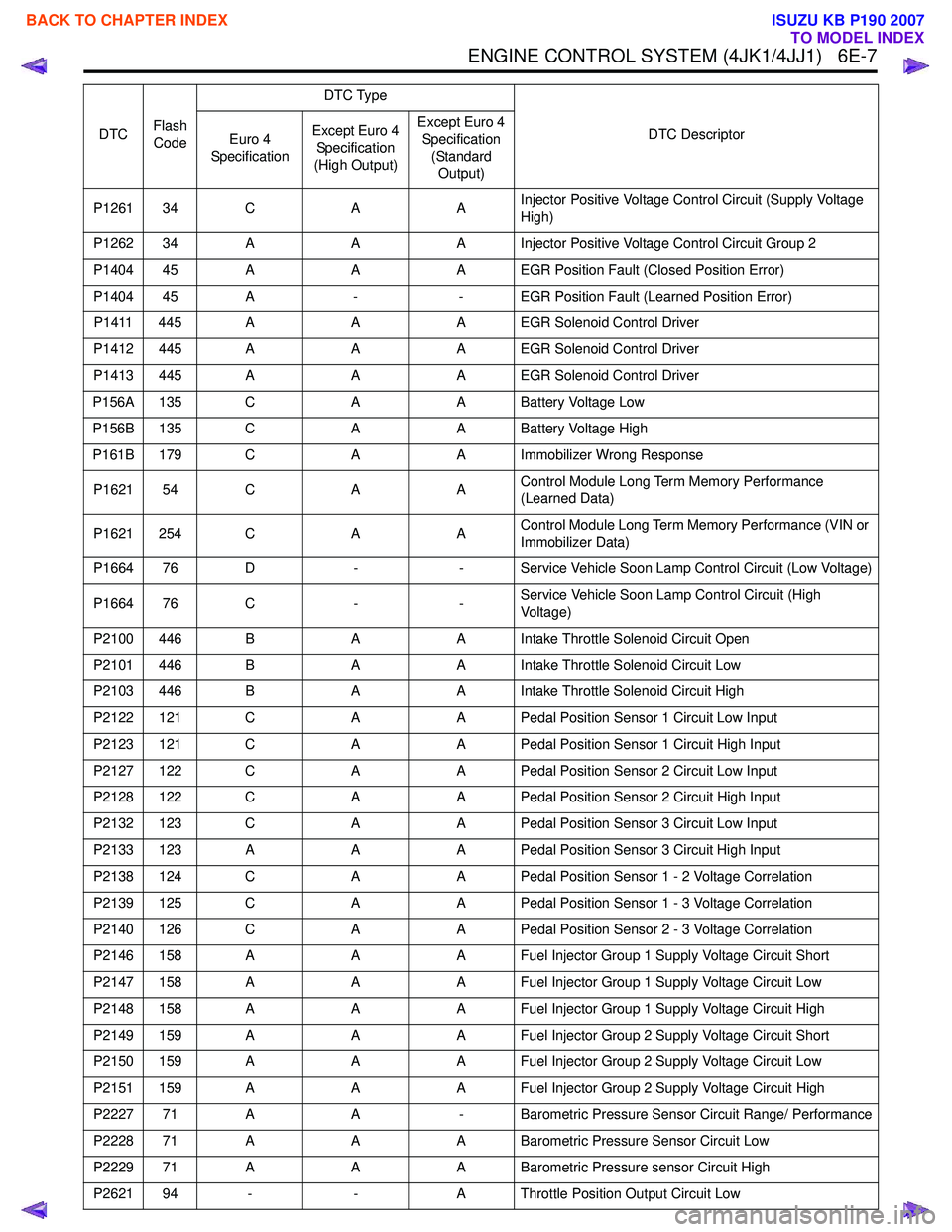
P1261 34 CAAInjector Positive Voltage Control Circuit (Supply Voltage
High)
P1262 34 A AA Injector Positive Voltage Control Circuit Group 2
P1404 45 A AA EGR Position Fault (Closed Position Error)
P1404 45 A -- EGR Position Fault (Learned Position Error)
P1411 445 A AA EGR Solenoid Control Driver
P1412 445 A AA EGR Solenoid Control Driver
P1413 445 A AA EGR Solenoid Control Driver
P156A 135 C AA Battery Voltage Low
P156B 135 C AA Battery Voltage High
P161B 179 C AA Immobilizer Wrong Response
P1621 54 C AAControl Module Long Term Memory Performance
(Learned Data)
P1621 254 C AAControl Module Long Term Memory Performance (VIN or
Immobilizer Data)
P1664 76 D -- Service Vehicle Soon Lamp Control Circuit (Low Voltage)
P1664 76 C --Service Vehicle Soon Lamp Control Circuit (High
Voltage)
P2100 446 B AA Intake Throttle Solenoid Circuit Open
P2101 446 B AA Intake Throttle Solenoid Circuit Low
P2103 446 B AA Intake Throttle Solenoid Circuit High
P2122 121 C AA Pedal Position Sensor 1 Circuit Low Input
P2123 121 C AA Pedal Position Sensor 1 Circuit High Input
P2127 122 C AA Pedal Position Sensor 2 Circuit Low Input
P2128 122 C AA Pedal Position Sensor 2 Circuit High Input
P2132 123 C AA Pedal Position Sensor 3 Circuit Low Input
P2133 123 A AA Pedal Position Sensor 3 Circuit High Input
P2138 124 C AA Pedal Position Sensor 1 - 2 Voltage Correlation
P2139 125 C AA Pedal Position Sensor 1 - 3 Voltage Correlation
P2140 126 C AA Pedal Position Sensor 2 - 3 Voltage Correlation
P2146 158 A AA Fuel Injector Group 1 Supply Voltage Circuit Short
P2147 158 A AA Fuel Injector Group 1 Supply Voltage Circuit Low
P2148 158 A AA Fuel Injector Group 1 Supply Voltage Circuit High
P2149 159 A AA Fuel Injector Group 2 Supply Voltage Circuit Short
P2150 159 A AA Fuel Injector Group 2 Supply Voltage Circuit Low
P2151 159 A AA Fuel Injector Group 2 Supply Voltage Circuit High
P2227 71 A A- Barometric Pressure Sensor Circuit Range/ Performance
P2228 71 A AA Barometric Pressure Sensor Circuit Low
P2229 71 A AA Barometric Pressure sensor Circuit High
P2621 94 - -A Throttle Position Output Circuit Low
DTC
Flash
Code DTC Type
DTC Descriptor
Euro 4
Specification Except Euro 4
Specification
(High Output) Except Euro 4
Specification (Standard Output)
BACK TO CHAPTER INDEX
TO MODEL INDEX
ISUZU KB P190 2007
Page 1626 of 6020
ENGINE CONTROL SYSTEM (4JK1/4JJ1) 6E-9
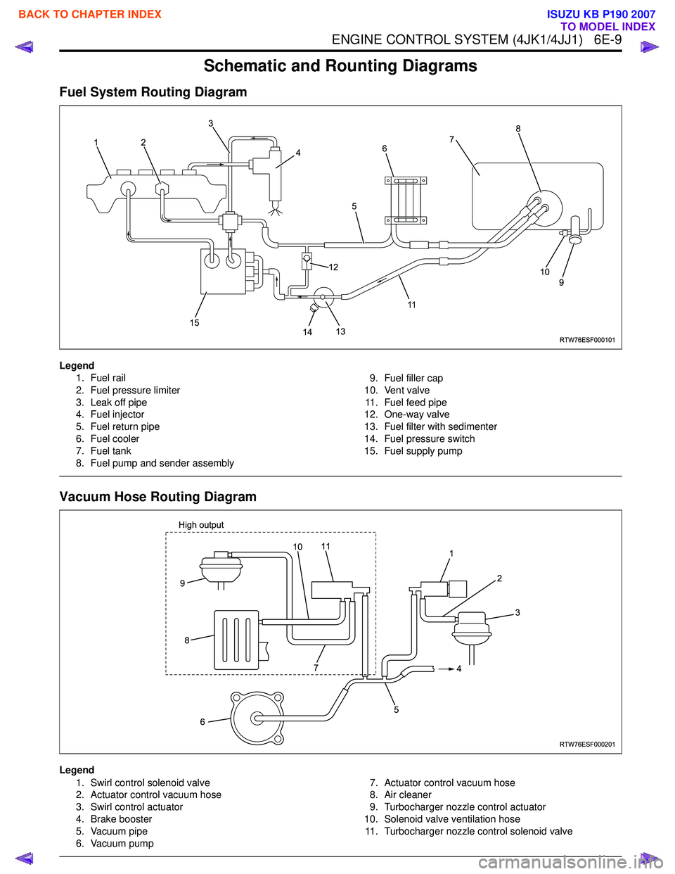
Schematic and Rounting Diagrams
Fuel System Routing Diagram
Legend1. Fuel rail
2. Fuel pressure limiter
3. Leak off pipe
4. Fuel injector
5. Fuel return pipe
6. Fuel cooler
7. Fuel tank
8. Fuel pump and sender assembly 9. Fuel filler cap
10. Vent valve 11. Fuel feed pipe
12. One-way valve
13. Fuel filter with sedimenter
14. Fuel pressure switch
15. Fuel supply pump
Vacuum Hose Routing Diagram
Legend
1. Swirl control solenoid valve
2. Actuator control vacuum hose
3. Swirl control actuator
4. Brake booster
5. Vacuum pipe
6. Vacuum pump 7. Actuator control vacuum hose
8. Air cleaner
9. Turbocharger nozzle control actuator
10. Solenoid valve ventilation hose 11. Turbocharger nozzle control solenoid valve
RTW76ESF000101
12 3
4
5
117
8
9
10
14
13
12
15
6
RTW76ESF000201
1 2
4
5
6
9
8
3
7
11
High output10
BACK TO CHAPTER INDEX
TO MODEL INDEX
ISUZU KB P190 2007
Page 1645 of 6020

6E-28 ENGINE CONTROL SYSTEM (4JK1/4JJ1)
Legend1. Boost pressure sensor
2. Turbocharger nozzle control solenoid
3. Barometric pressure (BARO) sensor (High output)
Legend
1. Exhaust gas recirculation (EGR) valve
2. Intake throttle valve
Legend
1. Engine control module (ECM)
2. Mass air flow (MAF) sensor / intake air templature
(IAT) sensor
Legend
1. Fuel rail pressure (FRP) sensor
2. Pressure limiter valve
3. Fuel rail
RTW76ESH003501
1
23
RTW56ESH002601
1
2
RTW56ESH003101
1
2
RTW76ESH002101123
BACK TO CHAPTER INDEX
TO MODEL INDEX
ISUZU KB P190 2007
Page 1646 of 6020

ENGINE CONTROL SYSTEM (4JK1/4JJ1) 6E-29
Legend1. Fuel temperature (FT) sensor
2. Fuel Rail Pressure (FRP) regulator
Legend
1. Fuel injector No.1 cylinder
2. Fuel injector No.2 cylinder
3. Fuel injector No.3 cylinder
4. Fuel injector No.4 cylinder
Legend
1. Swirl control solenoid valve
2. Swirl control actuator
Legend
1. Vehicle speed sensor (VSS) 2WD with A/T
2. Vehicle speed sensor (VSS) except 2WD with A/T
RTW56ESH002901
1
2
RTW56ESH003501
1
2
3
4
RTW76ESH002201
1 2
RTW56EMH000301
1
2
BACK TO CHAPTER INDEX
TO MODEL INDEX
ISUZU KB P190 2007
Page 1648 of 6020

ENGINE CONTROL SYSTEM (4JK1/4JJ1) 6E-31
Engine Control Module (ECM) Connector
End Views
Engine Control Module (ECM)-J1
Connector No. E-90
Connector Color Gray
Test Adapter No. J-35616-64A
Pin No. Wire Color Pin Function
1 — Not used
2 — Not used
3 — Not used
4 — Not used
5 — Not used
6 — Not used
7 — Not used
8 — Not used
9 — Not used
10 — Not used
11 — Not used
12 — Not used
13 — Not used
14 — Not used
15 — Not used
16 — Not used
17 ORN BARO sensor low reference
18 PNK/ GRN BARO sensor signal
19 BLU/ GRN BARO sensor 5V reference
20 GRN Boost pressure sensor 5V
reference
21 YEL Boost pressure sensor signal
RTW76ESH003101
12345678910111213141516
17 18 19 20 21 22 23 24 25 26 27 28 29 30 31 32
33 34 35 36 37 38 39 40 41 42 43 44 45 46 47 48 49 50 51 52
53 54 55 56 57 58 59 60 61 62 63 64 65 66 67 68 69 70 71 72
Pin No. Wire Color
Pin Function
22 BLK Boost pressure sensor shield
ground
23 BLU Boost pressure sensor low
reference
24 YEL Cylinder #2 fuel injector control
25 BRN Cylinder #3 fuel injector control
26 WHT ECT sensor low reference
27 GRN/ RED ECT sensor signal
28 YEL/ RED FT sensor low reference
29 PNK FT sensor signal
30 RED EGR position sensor low
reference
31 WHT/ BLU EGR position sensor 5V reference
32 GRY EGR position sensor signal
33 BLU/ YEL Cylinder #1 fuel injector control
34 BLU/ YEL FRP regulator control high side
35 BLU Intake throttle position sensor low
reference
36 GRY Intake throttle position sensor 5V
reference
37 GRN CKP sensor 5V reference
38 BLK CKP sensor shield ground
39 BLU CKP sensor low reference
40 ORN/ BLU MAF sensor signal
41 BLU/ RED IAT sensor signal
42 BLK MAF sensor shield ground
43 WHT/ BLU MAF sensor low reference
44 BLK CMP sensor low reference
45 WHT CMP sensor signal
46 RED CMP sensor 5V reference
47 RED FRP sensor 5V reference
48 WHT FRP sensor signal
49 BLK FRP sensor shield ground
50 BLU/ RED FRP regulator low side
51 WHT Cylinder #3 fuel injector charge
voltage
52 BLU Cylinder #1 fuel injector charge
voltage
53 GRN Cylinder #4 fuel injector control
54 BLK/ YEL FRP regulator control high side
55 WHT Intake throttle drive voltage
56 RED Intake throttle control low side
57 ORN Intake throttle position sensor
signal
BACK TO CHAPTER INDEX
TO MODEL INDEX
ISUZU KB P190 2007
Page 1656 of 6020

ENGINE CONTROL SYSTEM (4JK1/4JJ1) 6E-39
Fuel Injector No.4 Cylinder
Fuel Rail Pressure (FRP) Regulator Fuel Pump & Sender Assembly
Connector No.
E-16
Connector Color Gray
Test Adapter No. J-35616-64A
Pin No. Wire Color Pin Function
1 GRN Solenoid control
2 PNK Charge voltage
LNW46ESH001101
12
LNW46ESH001101
12
Connector No. E-50
Connector Color Gray
Test Adapter No. J-35616-64A
Pin No. Wire Color Pin Function
1 BLK/ YEL Control high side (PWM)
2 BLU/ RED Low side
Connector No. F-2
Connector Color White
Test Adapter No. J-35616-4A
Pin No. Wire Color Pin Function
1 ORN/ BLU Fuel pump motor voltage feed
2 BLK Fuel gauge ground
3 YEL/RED Fuel gauge signal
4 BLK Fuel pump motor ground
RTW76ESH003201
1234
BACK TO CHAPTER INDEX
TO MODEL INDEX
ISUZU KB P190 2007
Page 1657 of 6020

6E-40 ENGINE CONTROL SYSTEM (4JK1/4JJ1)
Fuel Rail Pressure (FRP) Sensor
Fuel Temperature (FT) Sensor Glow Plug
Mass Air Flow (MAF)/ Intake Air Temperature (IAT)
Sensor
Connector No. E-48
Connector Color Black
Test Adapter No. J-35616-64A
Pin No. Wire Color Pin Function
1 BLK Sensor low reference
2 WHT Sensor signal
3 RED Sensor 5V reference
LNW46ESH001501
12 3
LNW46ESH001201
12
Connector No. E-27
Connector Color Gray
Test Adapter No. J-35616-64A
Pin No. Wire Color Pin Function
1 YEL/ RED Sensor low reference
2 PNK Sensor signal
Connector No. E-49
Connector Color Silver
Pin No. Wire Color Pin Function 1 BLK/ RED Power supply
LNW46ESH000701
LNW46ESH001801
12345
BACK TO CHAPTER INDEX
TO MODEL INDEX
ISUZU KB P190 2007
Page 1664 of 6020

ENGINE CONTROL SYSTEM (4JK1/4JJ1) 6E-47
Scan Tool Data List
The Engine Scan Tool Data List contains all engine
related parameters that are available on the scan tool.
A given parameter may appear in any one of the data
lists, and in some cases may appear more than once,
or in more than one data list in order to group certain
related parameters together. Use the Engine Scan Tool
Data List only after the following is determined:
• The Engine Controls - Diagnostic System Check is completed. • On-board diagnostics are functioning properly.
Scan tool values from a properly running engine may
be used for comparison with the engine you are
diagnosing. The Engine Scan Tool Data List represents
values that would be seen on a normal running engine.
Only the parameters listed below are referenced in this
service manual for use in diagnosis.
Scan Tool Parameter Units Displayed Typical Data Value at Engine Idle Typical Data Value at 2000RPM
Operating Conditions: Engine idling or 2000RPM/ Engine coolant temperature is between 75 to 85 °C (167 to 185 °F)/
Accelerator pedal is constant/ Neutral or Park/ Accessories OFF/ Vehicle located at sea level
Engine Speed RPMNearly 700 RPM Nearly 2000 RPM
Desired Engine Idle Speed RPM700 RPM 700 RPM
Calculated Engine Load %- -
Coolant Temperature °C/ °F 75 to 85 °C/ 167 to 185 °F 75 to 85 °C/ 167 to 185 °F
Engine Coolant Temperature Sensor Volts
0.4 to 0.6 volts 0.4 to 0.6 volts
Intake Air Temperature °C/ °F 20 to 40 °C/ 68 to 104 °F 20 to 40 °C/ 68 to 104 °F
Intake Air Temperature Sensor Volts 1.4 to 2.3 volts1.4 to 2.3 volts
Fuel Temperature °C/ °F 20 to 60 °C/ 68 to 140 °F 20 to 60 °C/ 68 to 140 °F
Fuel Temperature Sensor Volts0.8 to 2.3 volts 0.8 to 2.3 volts
MAF (Mass Air Flow) g/sec300 to 600 g/sec 200 to 600 g/sec
MAF Sensor (Mass Air Flow) Volts1.2 to 1.6 volts 2.0 to 2.7 volts
Barometric Pressure kPa/psi Nearly 100 kPa/ 14.5 psi at sea
levelNearly 100 kPa/ 14.5 psi at sea
level
Barometric Pressure Sensor VoltsNearly 2.3 volts at sea level Nearly 2.3 volts at sea level
Turbocharger Solenoid Command %
50 to 60 % 50 to 60 %
Desired Boost Pressure kPa/ psi Nearly 100 kPa/ 14.5 psi at sea
levelLess than 120 kPa/ 17.4 psi
Boost Pressure kPa/ psi Nearly 100 kPa/ 14.5 psi at sea
levelLess than 120 kPa/ 17.4 psi
Boost Pressure Sensor VoltsNearly 1.0 volt Less than 1.3 volts
Desired Fuel Rail Pressure MPa/ psi 30 MPa/ 4,350 psiMore than 70 MPa/ 10,200 psi
(4JJ1 Euro 4 specification)
More than 50 MPa/ 7,250 psi
(4JJ1 except Euro 4 specification)
More than 60 MPa/ 8,700 psi
(4JK1)
Fuel Rail Pressure MPa/ psi 27 to 33 MPa/ 3,900 to 4,800 psi More than 70 MPa/ 10,200 psi
(4JJ1 Euro 4 specification)
More than 50 MPa/ 7,250 psi (4JJ1 except Euro 4 specification)
More than 60 MPa/ 8,700 psi (4JK1)
BACK TO CHAPTER INDEX
TO MODEL INDEX
ISUZU KB P190 2007
Page 1665 of 6020

6E-48 ENGINE CONTROL SYSTEM (4JK1/4JJ1)
Fuel Rail Pressure SensorVolts1.4 to 1.5 volts More than 2.1 volts (4JJ1 Euro 4
specification)
More than 1.8 volts (4JJ1 except Euro 4 specification)
More than 1.9 volts (4JK1)
FRP Regulator Command (Fuel Rail Pressure) %
35 to 50 % 35 to 45 %
FRP Regulator Commanded Fuel Flow mm
3/sec More than 1,000 mm3/sec More than 2,000 mm3/sec
FRP Regulator Feedback (Fuel Rail Pressure) mA
1,600 to 2,000 mA 1,500 to 1,800 mA
Accelerator Pedal Position %0% 10 to 25 %
APP Sensor 1 (Accelerator Pedal Position) Volts
0.2 to 1.0 volts 1.0 to 1.7 volts
APP Sensor 2 (Accelerator Pedal Position) Volts
3.8 to 4.6 volts 3.3 to 3.9 volts
APP Sensor 3 (Accelerator Pedal Position) Volts
3.8 to 4.6 volts 3.7 to 4.0 volts
EGR Solenoid Command %Less than 30 % Less than 30 %
Desired EGR Position %Less than 70 % Less than 80 %
EGR Position %Less than 70 % Less than 80 %
EGR Position Sensor VoltsLess than 2.9 volts Less than 3.1 volts
Intake Throttle Solenoid Command %
Less than 30 % Less than 40 %
Desired Intake Throttle Position %Less than 30 % Less than 80 %
Intake Throttle Position %Less than 30 % Less than 80 %
Intake Throttle Position Sensor Volts Less than 1.6 voltsLess than 3.3 volts
Desired Injection Quantity mm
37 to 12 mm37 to 12 mm3
Main Injection Quantitymm33 to 8 mm35 to 10 mm3
Main Injection Timing°CA 2 to 12 °CA 0 to 10 °CA
Main Injection On Time ms600 to 800 ms 400 to 550 ms
Pre Injection Quantity mm
31 to 4 mm32 to 4 mm3
Pre Injection Interval°CA 3 to 20 °CA 10 to 30 °CA
Fuel Compensation Cyl. 1 mm
3-5.0 to 5.0 mm3 (varies)0.0 mm3
Fuel Compensation Cyl. 2 mm3-5.0 to 5.0 mm3 (varies)0.0 mm3
Fuel Compensation Cyl. 3 mm3-5.0 to 5.0 mm3 (varies)0.0 mm3
Fuel Compensation Cyl. 4 mm3-5.0 to 5.0 mm3 (varies)0.0 mm3
Cylinder Balancing Update Enabled/ Disabled EnabledDisabled
Fuel Supply Pump Status Not Learn/ Learning/ LearnedLearning or Learned
Learning or Learned
Rail Pressure Feedback Mode Wait Mode/ Feedback Mode/ Shutoff Mode Feedback Mode
Feedback Mode
Engine Running Status Off/ Ignition On/ Cranking/ Running Running
Running
Scan Tool Parameter Units Displayed Typical Data Value at Engine Idle Typical Data Value at 2000RPM
BACK TO CHAPTER INDEX
TO MODEL INDEX
ISUZU KB P190 2007
Page 1667 of 6020

6E-50 ENGINE CONTROL SYSTEM (4JK1/4JJ1)
Scan Tool Data Definitions
This information will assist in emission or driveability
problems. The displays can be viewed while the vehicle
is being driven. Always perform the Diagnostic System
Check - Engine Controls first. The Diagnostic System
Check will confirm proper system operation.
Engine Speed
This parameter displays the rotational speed of the
crankshaft as calculated by the ECM based on inputs
from the crankshaft position (CKP) sensor or camshaft
position (CMP) sensor.
Desired Idle Speed
This parameter displays the idle speed requested by
the ECM. The ECM will change desired idle speed
based on engine coolant temperature and other inputs.
Calculate Engine Load
This parameter displays the engine load in percent
based on inputs to the ECM from various engine
sensors. The scan tool will display a lower percentage
when the engine is at idle with little or no load. The
scan tool will display a higher percentage when the
engine is running at high engine speed under a heavy
load.
Coolant Temperature
This parameter displays the temperature of the engine
coolant as calculated by the ECM using the signal from
the engine coolant temperature (ECT) sensor. The
scan tool will display a low temperature when the ECT
sensor signal voltage is high, and a high temperature
when the ECT sensor signal voltage is low.
Engine Coolant Temperature Sensor
This parameter displays the voltage signal sent to the
ECM from the engine coolant temperature (ECT)
sensor. ECT sensor is a range of value indicating a low
voltage when the temperature is high, and a high
voltage when the temperature is low.
Intake Air Temperature
This parameter displays the temperature of the intake
air as calculated by the ECM using the signal from the
intake air temperature (IAT) sensor. The scan tool will
display a low temperature when the IAT sensor signal
voltage is high, and a high temperature when the IAT
sensor signal voltage is low. Intake Air Temperature Sensor
This parameter displays the voltage signal sent to the
ECM from the intake air temperature (IAT) sensor. IAT
sensor is a range of value indicating a low voltage
when the temperature is high, and a high voltage when
the temperature is low.
Fuel Temperature
This parameter displays the temperature of the fuel as
calculated by the ECM using the signal from the fuel
temperature (FT) sensor. The scan tool will display a
low temperature when the FT sensor signal voltage is
high, and a high temperature when the FT sensor
signal voltage is low.
Fuel Temperature Sensor
This parameter displays the voltage signal sent to the
ECM from the fuel temperature (FT) sensor. FT sensor
is a range of value indicating a low voltage when the
temperature is high, and a high voltage when the
temperature is low.
MAF (Mass Air Flow)
This parameter displays the air flow into the engine as
calculated by the ECM based on the mass air flow
(MAF) sensor input. The scan tool will display a high
value at higher engine speeds, and a low value at lower
engine speed.
MAF Sensor (Mass Air Flow)
This parameter displays the voltage signal sent to the
ECM from the mass air flow (MAF) sensor. MAF sensor
is a range of value indicating a low voltage at lower
engine speed, and a high voltage at a higher engine
speeds.
Barometric Pressure
This parameter displays the barometric pressure
(BARO) as calculated by the ECM using the signal from
the BARO sensor. The scan tool will display a low
barometric pressure in high altitude area.
Barometric Pressure Sensor
This parameter displays the voltage signal sent to the
ECM from the barometric pressure (BARO) sensor.
BARO sensor is a range of value indicating a low
voltage in high altitude area, and a middle voltage in
sea level.
Immobilizer Signal Yes/ NoYes Yes
Security Wait Time Inactive/ Time
(hour: minute: second) Inactive
Inactive
Scan Tool Parameter Units Displayed Typical Data Value at Engine Idle Typical Data Value at 2000RPM
BACK TO CHAPTER INDEX
TO MODEL INDEX
ISUZU KB P190 2007