check engine light ISUZU KB P190 2007 Workshop Repair Manual
[x] Cancel search | Manufacturer: ISUZU, Model Year: 2007, Model line: KB P190, Model: ISUZU KB P190 2007Pages: 6020, PDF Size: 70.23 MB
Page 20 of 6020
0B-2 MAINTENANCE AND LUBRICATION
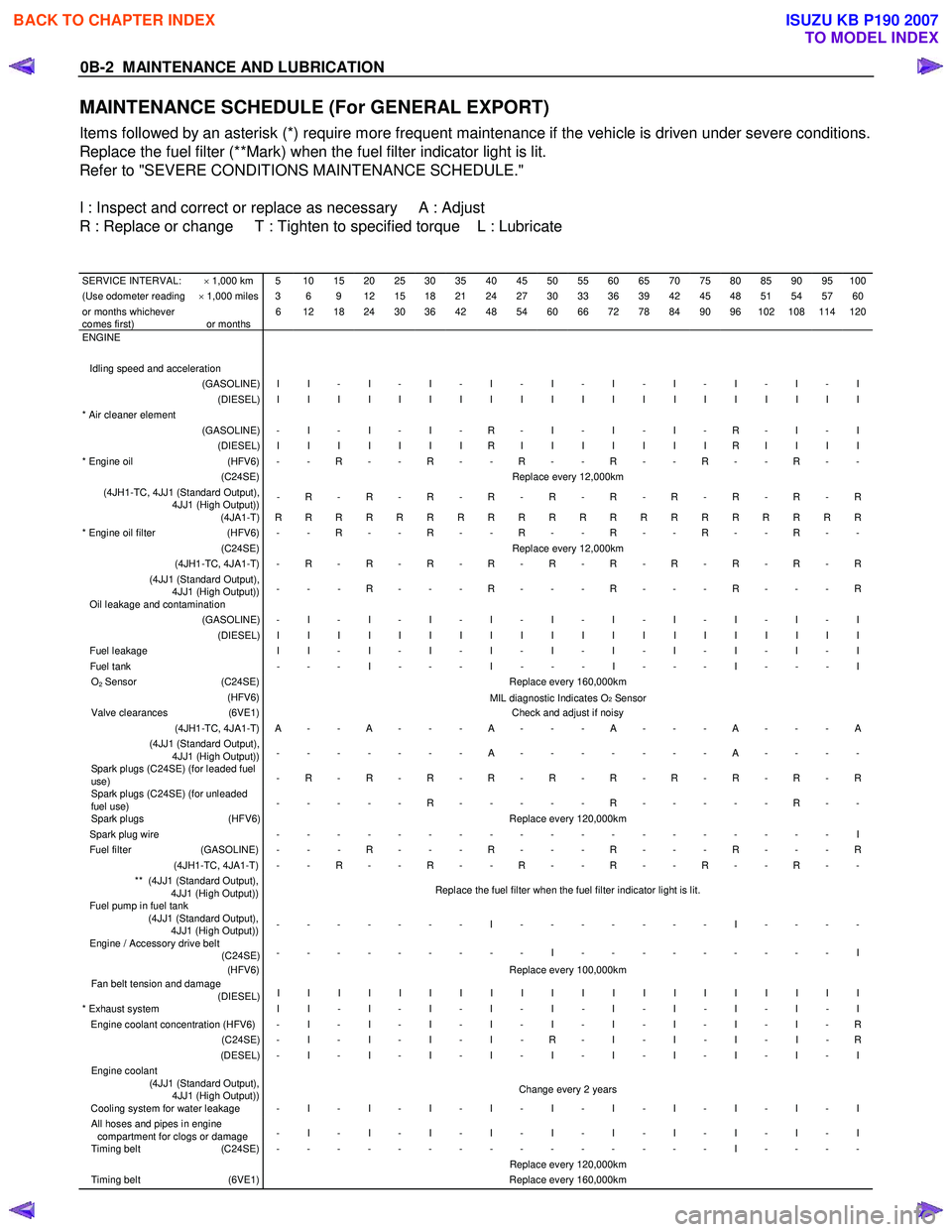
MAINTENANCE SCHEDULE (For GENERAL EXPORT)
Items followed by an asterisk (*) require more frequent maintenance if the vehicle is driven under severe conditions.
Replace the fuel filter (**Mark) when the fuel filter indicator light is lit.
Refer to "SEVERE CONDITIONS MAINTENANCE SCHEDULE."
I : Inspect and correct or replace as necessary A : Adjust
R : Replace or change T : Tighten to specified torque L : Lubricate
SERVICE INTERVAL: × 1,000 km 5 10 15 20 25 30 35 40 45 50 55 60 65 70 75 80 85 90 95 100(Use odometer reading × 1,000 miles 3 6 9 12 15 18 21 24 27 30 33 36 39 42 45 48 51 54 57 60or months whichever
comes first)
or months 6 12 18 24 30 36 42 48 54 60 66 72 78 84 90 96 102 108 114 120
ENGINE
Idling speed and acceleration
(GASOLINE) I I - I - I - I - I - I - I - I - I - I (DIESEL) I I I I I I I I I I I I I I I I I I I I * Air cleaner element
(GASOLINE) - I - I - I - R - I - I - I - R - I - I (DIESEL) I I I I I I I R I I I I I I I R I I I I * Engine oil (HFV6) - - R - - R - - R - - R - - R - - R - - (C24SE) Replace every 12,000km (4JH1-TC, 4JJ1 (Standard Output),
4JJ1 (High Output)) - R - R - R - R - R - R - R - R - R - R
(4JA1-T) R R R R R R R R R R R R R R R R R R R R * Engine oil filter (HFV6) - - R - - R - - R - - R - - R - - R - - (C24SE) Replace every 12,000km (4JH1-TC, 4JA1-T) - R - R - R - R - R - R - R - R - R - R (4JJ1 (Standard Output),
4JJ1 (High Output)) - - - R - - - R - - - R - - - R - - - R
Oil leakage and contamination (GASOLINE) - I - I - I - I - I - I - I - I - I - I (DIESEL) I I I I I I I I I I I I I I I I I I I I Fuel leakage
I I - I - I - I - I - I - I - I - I - I Fuel tank - - - I - - - I - - - I - - - I - - - I O2 Sensor (C24SE) Replace every 160,000km (HFV6)
MIL diagnostic Indicates O2 Sensor Valve clearances (6VE1) Check and adjust if noisy (4JH1-TC, 4JA1-T) A - - A - - - A - - - A - - - A - - - A (4JJ1 (Standard Output),
4JJ1 (High Output)) - - - - - - - A - - - - - - - A - - - -
Spark plugs (C24SE) (for leaded fuel
use) - R - R - R - R - R - R - R - R - R - R
Spark plugs (C24SE) (for unleaded
fuel use) - - - - - R - - - - - R - - - - - R - -
Spark plugs
(HFV6) Replace every 120,000km Spark plug wire - - - - - - - - - - - - - - - - - - - I Fuel filter (GASOLINE) - - - R - - - R - - - R - - - R - - - R (4JH1-TC, 4JA1-T) - - R - - R - - R - - R - - R - - R - - ** (4JJ1 (Standard Output),
4JJ1 (High Output)) Replace the fuel filter when the fuel filter indicator light is lit.
Fuel pump in fuel tank
(4JJ1 (Standard Output),
4JJ1 (High Output)) - - - - - - - I - - - - - - - I - - - -
Engine / Accessory drive belt
(C24SE) - - - - - - - - - I - - - - - - - - - I
(HFV6) Replace every 100,000km Fan belt tension and damage
(DIESEL) I I I I I I I I I I I I I I I I I I I I
* Exhaust system
I I - I - I - I - I - I - I - I - I - I Engine coolant concentration (HFV6) - I - I - I - I - I - I - I - I - I - R (C24SE) - I - I - I - I - R - I - I - I - I - R (DESEL) - I - I - I - I - I - I - I - I - I - I Engine coolant
(4JJ1 (Standard Output),
4JJ1 (High Output)) Change every 2 years
Cooling system for water leakage - I - I - I - I - I - I - I - I - I - I All hoses and pipes in engine
compartment for clogs or damage - I - I - I - I - I - I - I - I - I - I
Timing belt
(C24SE) - - - - - - - - - - - - - - - I - - - - Replace every 120,000km Timing belt (6VE1) Replace every 160,000km
BACK TO CHAPTER INDEX
TO MODEL INDEX
ISUZU KB P190 2007
Page 72 of 6020
1-38 HEATER AND AIR CONDITIONING
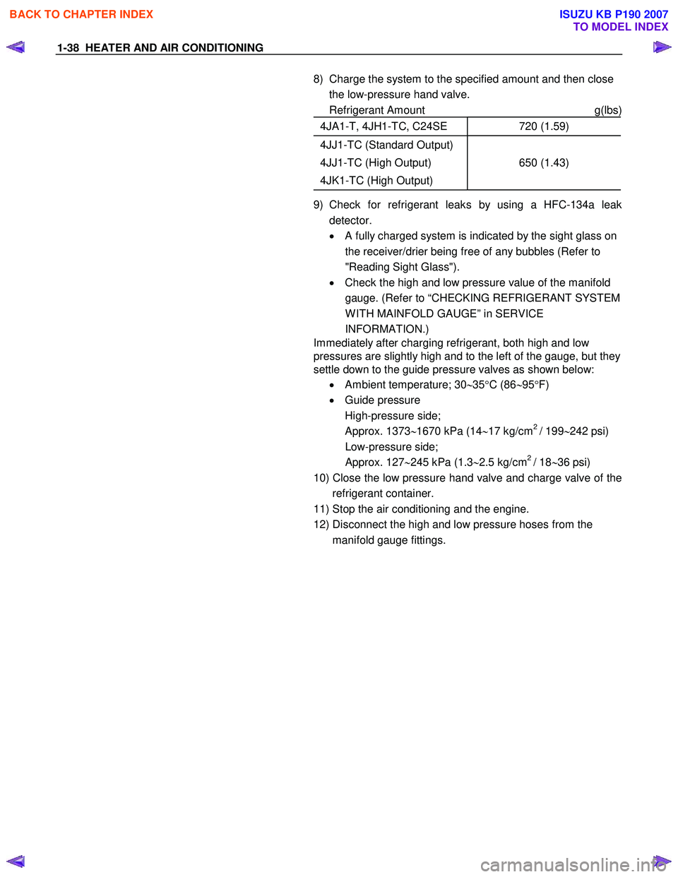
8) Charge the system to the specified amount and then close the low-pressure hand valve.
Refrigerant Amount g(lbs)
4JA1-T, 4JH1-TC, C24SE 720 (1.59)
4JJ1-TC (Standard Output)
4JJ1-TC (High Output)
4JK1-TC (High Output)
650 (1.43)
9) Check for refrigerant leaks by using a HFC-134a leak detector.
• A fully charged system is indicated by the sight glass on
the receiver/drier being free of any bubbles (Refer to
"Reading Sight Glass").
• Check the high and low pressure value of the manifold
gauge. (Refer to “CHECKING REFRIGERANT SYSTEM
W ITH MAINFOLD GAUGE” in SERVICE
INFORMATION.)
Immediately after charging refrigerant, both high and low
pressures are slightly high and to the left of the gauge, but they
settle down to the guide pressure valves as shown below:
• Ambient temperature; 30 ∼35 °C (86 ∼95 °F)
• Guide pressure
High-pressure side;
Approx. 1373 ∼1670 kPa (14 ∼17 kg/cm
2 / 199 ∼242 psi)
Low-pressure side;
Approx. 127 ∼245 kPa (1.3 ∼2.5 kg/cm
2 / 18 ∼36 psi)
10) Close the low pressure hand valve and charge valve of the refrigerant container.
11) Stop the air conditioning and the engine.
12) Disconnect the high and low pressure hoses from the manifold gauge fittings.
BACK TO CHAPTER INDEX
TO MODEL INDEX
ISUZU KB P190 2007
Page 73 of 6020
HEATER AND AIR CONDITIONING 1-39
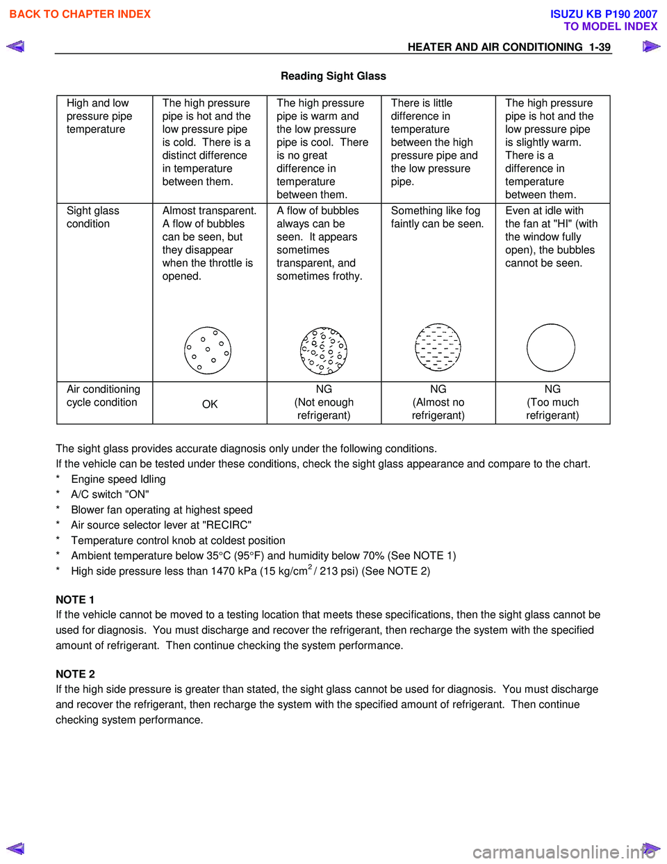
Reading Sight Glass
High and low
pressure pipe
temperature The high pressure
pipe is hot and the
low pressure pipe
is cold. There is a
distinct difference
in temperature
between them. The high pressure
pipe is warm and
the low pressure
pipe is cool. There
is no great
difference in
temperature
between them. There is little
difference in
temperature
between the high
pressure pipe and
the low pressure
pipe. The high pressure
pipe is hot and the
low pressure pipe
is slightly warm.
There is a
difference in
temperature
between them.
Sight glass
condition Almost transparent.
A flow of bubbles
can be seen, but
they disappear
when the throttle is
opened.
A flow of bubbles
always can be
seen. It appears
sometimes
transparent, and
sometimes frothy.
Something like fog
faintly can be seen.
Even at idle with
the fan at "HI" (with
the window fully
open), the bubbles
cannot be seen.
Air conditioning
cycle condition
OK NG
(Not enough refrigerant) NG
(Almost no
refrigerant) NG
(Too much
refrigerant)
The sight glass provides accurate diagnosis only under the following conditions.
If the vehicle can be tested under these conditions, check the sight glass appearance and compare to the chart.
* Engine speed Idling
* A/C switch "ON"
* Blower fan operating at highest speed
* Air source selector lever at "RECIRC"
* Temperature control knob at coldest position
* Ambient temperature below 35 °C (95 °F) and humidity below 70% (See NOTE 1)
* High side pressure less than 1470 kPa (15 kg/cm
2 / 213 psi) (See NOTE 2)
NOTE 1
If the vehicle cannot be moved to a testing location that meets these specifications, then the sight glass cannot be
used for diagnosis. You must discharge and recover the refrigerant, then recharge the system with the specified
amount of refrigerant. Then continue checking the system performance.
NOTE 2
If the high side pressure is greater than stated, the sight glass cannot be used for diagnosis. You must discharge
and recover the refrigerant, then recharge the system with the specified amount of refrigerant. Then continue
checking system performance.
BACK TO CHAPTER INDEX
TO MODEL INDEX
ISUZU KB P190 2007
Page 200 of 6020
SHEET METAL 2B-3
RUW 52BSH002501
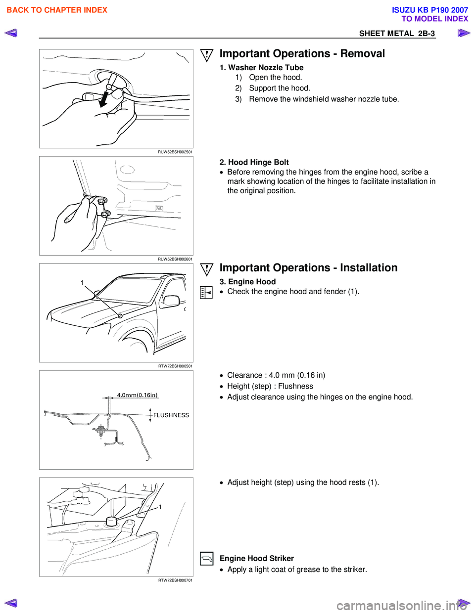
Important Operations - Removal
1. Washer Nozzle Tube
1) Open the hood.
2) Support the hood.
3) Remove the windshield washer nozzle tube.
RUW 52BSH002601
2. Hood Hinge Bolt
• Before removing the hinges from the engine hood, scribe a
mark showing location of the hinges to facilitate installation in
the original position.
RTW 72BSH000501
Important Operations - Installation
3. Engine Hood
• Check the engine hood and fender (1).
• Clearance : 4.0 mm (0.16 in)
• Height (step) : Flushness
• Adjust clearance using the hinges on the engine hood.
RTW 72BSH000701
• Adjust height (step) using the hood rests (1).
Engine Hood Striker
• Apply a light coat of grease to the striker.
BACK TO CHAPTER INDEX
TO MODEL INDEX
ISUZU KB P190 2007
Page 206 of 6020
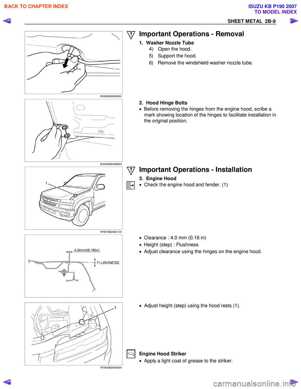
SHEET METAL 2B-9
RUW 52BSH002501
Important Operations - Removal
1. Washer Nozzle Tube
4) Open the hood.
5) Support the hood.
6) Remove the windshield washer nozzle tube.
RUW 52BSH002601
2. Hood Hinge Bolts
• Before removing the hinges from the engine hood, scribe a
mark showing location of the hinges to facilitate installation in
the original position.
RTW 72BSH001101
Important Operations - Installation
3. Engine Hood
• Check the engine hood and fender. (1)
• Clearance : 4.0 mm (0.16 in)
• Height (step) : Flushness
• Adjust clearance using the hinges on the engine hood.
RTW 52BSH000301
• Adjust height (step) using the hood rests (1).
Engine Hood Striker
• Apply a light coat of grease to the striker.
BACK TO CHAPTER INDEX
TO MODEL INDEX
ISUZU KB P190 2007
Page 269 of 6020
3B-8 POWER-ASSISTED STEERING SYSTEM
6. Fully close the shutoff valve. Record the highest
pressures.
・ If the pressure recorded is within 9800-10300 kPa
(100-105 kg/cm
2/1422-1493psi), the pump is
functioning within its specifications.
・ If the pressure recorded is higher than 10300 kPa
(105 kg/cm
2/1493psi), the valve in the pump is
defective.
・ If the pressure recorded is lower than 9800 kPa
(100 kg/cm
2/1422psi), the valve or the rotating
assembly in the pump is defective.
7. If the pump pressures are within specifications, leave the valve open and turn (or have someone
else turn) the steering wheel fully in both directions.
Record the highest pressures and compare with the
maximum pump pressure recorded in step 6. If this
pressure cannot be built up at either side of the
power steering unit, the power steering unit is
leaking internally and must be replaced.
8. Shut the engine off, remove the testing gauge.
9. Reconnect the pressure hose, check the fluid level and make the needed repairs.
10. If the problem still exists, the steering and front suspension must be thoroughly examined.
Maintenance
The hydraulic system should be kept clean, the fluid
level in the reservoir should be checked at regula
r
intervals and fluid added when required. Refer to
Recommended Fluids and Lubricants in General
Information section for the type of fluid to be used and
the intervals for filling.
If the system contains some dirt, flush it as described in
this section. If it is exceptionally dirty, the pump must be
completely disassembled before further usage. (The
steering unit cannot be disassembled.)
All tubes, hoses, and fittings should be inspected for
leakage at regular intervals. Fittings must be tight. Make
sure the clips, clamps and supporting tubes and hoses
are in place and properly secured.
Power steering hoses and lines must not be twisted,
kinked or tightly bent. Air in the system will cause
spongy action and noisy operation. W hen a hose is
disconnected or when fluid is lost, for any reason, the
system must be bled after refilling. Refer to Bleeding the
Power Steering System in this section.
・ Inspect gear for looseness or damage.
・ Inspect hoses to insure they are not touching an
y
other parts of the vehicle.
・ Inspect fluid level and fill to the proper level.
Fluid Level
1. Run the engine until the power steering fluid
reaches normal operating temperature, about 55 °
C (130 °F), then shut the engine off.
2. Check the level of fluid in the reservoir.
3. If the fluid level is low, add power steering fluid as
specified in General Information to the proper level
and install the receiver cap.
4. W hen checking the fluid level after the steering system has been serviced, air must be bled from
the system. Refer to Bleeding the Power Steering
System in this section.
Bleeding the Power Steering System
W hen a power steering pump or unit has been installed,
or an oil line has been disconnected, the air that has
entered the system must be bled out before the vehicle
is operated. If air is allowed to remain in the powe
r
steering fluid system, noisy and unsatisfactory operation
of the system may result.
Bleeding Procedure
W hen bleeding the system, and any time fluid is added
to the power steering system, be sure to use only powe
r
steering fluid as specified in General Information.
1. Fill the pump fluid reservoir to the proper level and let the fluid settle for at least two minutes.
2. Start the engine and let it run for a few seconds. Do not turn the steering wheel. Then turn the engine
off.
3. Add fluid if necessary.
4. Repeat the above procedure until the fluid level remains constant after running the engine.
5. Raise and support the front end of the vehicle so that the wheels are off the ground.
6. Start the engine. Slowly turn the steering wheel right and left, lightly contacting the wheel stops.
7. Add power steering fluid if necessary.
8. Lower the vehicle, set the steering wheel at the straight forward position after turning it to its full
steer positions 2 or 3 times, and stop the engine.
9. Check the fluid level and refill as required.
10. If the fluid is extremely foamy, allow the vehicle to settle for a few minutes, then repeat the above
procedure.
Flushing the Power Steering System
1. Raise and support the front end of the vehicle off
the ground until the wheels are free to turn.
2. Remove the fluid return line at the pump inlet connector and plug the connector port on the pump.
Direct the line toward a large container to catch the
draining fluid.
3. W hile running the engine at idle, fill the reservoi
r
with new power steering fluid. Turn the steering
wheel in both directions. Do not contact or hold the
steering wheel to the wheel stops. This will cause
the pump to go to pressure relief mode, which ma
y
cause a sudden fluid overflow at the reservoir.
BACK TO CHAPTER INDEX
TO MODEL INDEX
ISUZU KB P190 2007
Page 305 of 6020
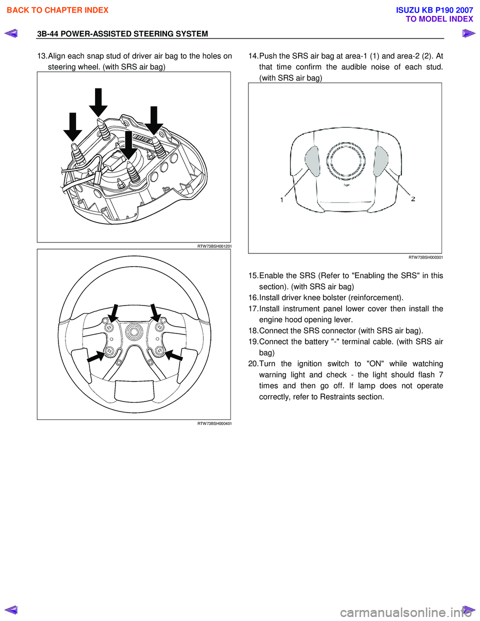
3B-44 POWER-ASSISTED STEERING SYSTEM
13. Align each snap stud of driver air bag to the holes on
steering wheel. (with SRS air bag)
RTW 73BSH001201
RTW 73BSH000401
14. Push the SRS air bag at area-1 (1) and area-2 (2). At
that time confirm the audible noise of each stud.
(with SRS air bag)
RTW 73BSH000301
15. Enable the SRS (Refer to "Enabling the SRS" in this
section). (with SRS air bag)
16. Install driver knee bolster (reinforcement).
17. Install instrument panel lower cover then install the engine hood opening lever.
18. Connect the SRS connector (with SRS air bag).
19. Connect the battery "-" terminal cable. (with SRS ai
r
bag)
20. Turn the ignition switch to "ON" while watching warning light and check - the light should flash 7
times and then go off. If lamp does not operate
correctly, refer to Restraints section.
BACK TO CHAPTER INDEX
TO MODEL INDEX
ISUZU KB P190 2007
Page 617 of 6020
5A-24 BRAKE CONTROL SYSTEM
Computer System Service Precautions
The Anti-lock Brake System and Electronic Brake-force
Distribution interfaces directly with the Electronic
Hydraulic Control Unit (EHCU) which is a control
computer that is similar in some regards to the Engine
Control Module. These modules are designed to
withstand normal current draws associated with vehicle
operation. However, care must be taken to avoid
overloading any of the EHCU circuits. In testing for
opens or shorts, do not ground or apply voltage to any
of the circuits unless instructed to do so by the
appropriate diagnostic procedure. These circuits should
only be tested with a high impedance multimeter
5-8840-0366-0 or special tools as described in this
section. Power should never be removed or applied to
any control module with the ignition in the “ON” position.
Before removing or connecting battery cables, fuses or
connectors, always turn the ignition switch to the “OFF”
position.
General Service Precautions
The following are general precautions which should be
observed when servicing and diagnosing the Anti-lock
Brake System and/or other vehicle systems. Failure to
observe these precautions may result in Anti-lock Brake
System and Electronic Brake-force Distribution
damage.
• If welding work is to be performed on the vehicle using an electric arc welder, the EHCU and valve
block connectors should be disconnected before the
welding operation begins.
• The EHCU and valve block connectors should never be connected or disconnected with the
ignition “ON”.
Note:
• If only rear wheels are rotated using jacks or drum tester, the system will diagnose a speed sensor
malfunction and the “ABS and Brake” warning lamp
will illuminate. But actually no trouble exists. W hen
the DTC is not detected and the ABS and BRAKE
warning lamp is on, “How to erase code” is
performed and an ABS and BRAKE warning lamp
are off.
If the battery has been discharged
The engine may stall if the battery has been completely
discharged and the engine is started via jumper cables.
This is because the Anti-lock Brake System (ABS) and
Electronic Brake-force Distribution (EBD) System
requires a large quantity of electricity. In this case, wait
until the battery is recharged, or set the ABS and EBD
to a non-operative state by removing the fuse for the
ABS. After the battery has been recharged, stop the
engine and install the ABS fuse. Start the engine again,
and confirm that the ABS warning Lamp does not light.
Note on Intermittents
As with virtually any electronic system, it is difficult to
identify an intermittent failure. In such a case duplicating
the system malfunction during a test drive or a good
description of vehicle behavior from the customer may
be helpful in locating a “most likely” failed component or
circuit. The symptom diagnosis chart may also be
useful in isolating the failure. Most intermittent
problems are caused by faulty electrical connections or
wiring. W hen an intermittent failure is encountered,
check suspect circuits for:
• Suspected harness damage.
• Poor mating of connector halves or terminals not fully seated in the connector body (backed out).
• Improperly formed or damaged terminals.
Test Driving ABS Complaint Vehicles
If there has been an abnormality in the lighting pattern
of the “ABS” warning lamp, the fault can be located in
accordance with the “DIAGNOSIS BY “ABS” W ARNING
LAMP ILLUMINATION PATTERN”. Although such
problems can be detected by the driver as a vehicle
symptom, it is still necessary to perform a test drive
following the test procedure mentioned below, in order
to reproduce the symptom for problem diagnosis on a
symptom basis:
1. Start the engine and make sure that the “ABS” W /L
goes OFF. If the W /L remains ON, it means that
the Diagnostic Trouble Code (DTC) is stored.
Therefore, read the code and locate the fault.
Note: The DTC cannot be cleared if the vehicle speed
does not exceed about 10km/h (6mph) at DTC, even
though the repair operation is completed.
2. Start the vehicle and accelerate to about 30 km/h (19 mph) or more.
3. Slowly brake and stop the vehicle completely.
4. Then restart the vehicle and accelerate to about 40 km/h (25 mph) or more.
5. Brake at a time so as to actuate the ABS and stop the vehicle.
6. Be cautious of abnormality during the test. If the W /L is actuated while driving, read the DTC and
locate the fault.
7. If the abnormality is not reproduced by the test, make best efforts to reproduce the situation
reported by the customer.
8. If the abnormality has been detected, repair in accordance with the “SYMPTOM DIAGNOSIS”.
Note:
• Be sure to perform a test drive on a wide, even road
with light traffic.
• If an abnormality is detected, be sure to suspend the test and start trouble diagnosis at once.
BACK TO CHAPTER INDEX
TO MODEL INDEX
ISUZU KB P190 2007
Page 640 of 6020
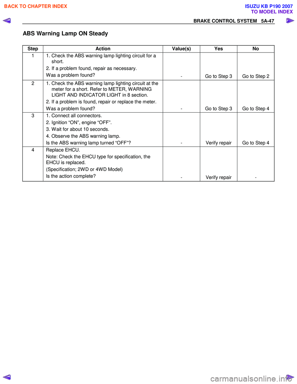
BRAKE CONTROL SYSTEM 5A-47
ABS Warning Lamp ON Steady
Step Action Value(s) Yes No
1 1. Check the ABS warning lamp lighting circuit for a
short.
2. If a problem found, repair as necessary. W as a problem found? - Go to Step 3 Go to Step 2
2 1. Check the ABS warning lamp lighting circuit at the
meter for a short. Refer to METER, W ARNING
LIGHT AND INDICATOR LIGHT in 8 section.
2. If a problem is found, repair or replace the meter. W as a problem found? - Go to Step 3 Go to Step 4
3 1. Connect all connectors.
2. Ignition “ON”, engine “OFF”.
3. W ait for about 10 seconds.
4. Observe the ABS warning lamp. Is the ABS warning lamp turned “OFF”? - Verify repair Go to Step 4
4 Replace EHCU.
Note: Check the EHCU type for specification, the
EHCU is replaced.
(Specification; 2W D or 4W D Model)
Is the action complete? - Verify repair -
BACK TO CHAPTER INDEX
TO MODEL INDEX
ISUZU KB P190 2007
Page 829 of 6020
6A – 24 ENGINE MECHANICAL
SERVICING
Servicing refers to general maintenance procedures to be performed by qualified service personnel.
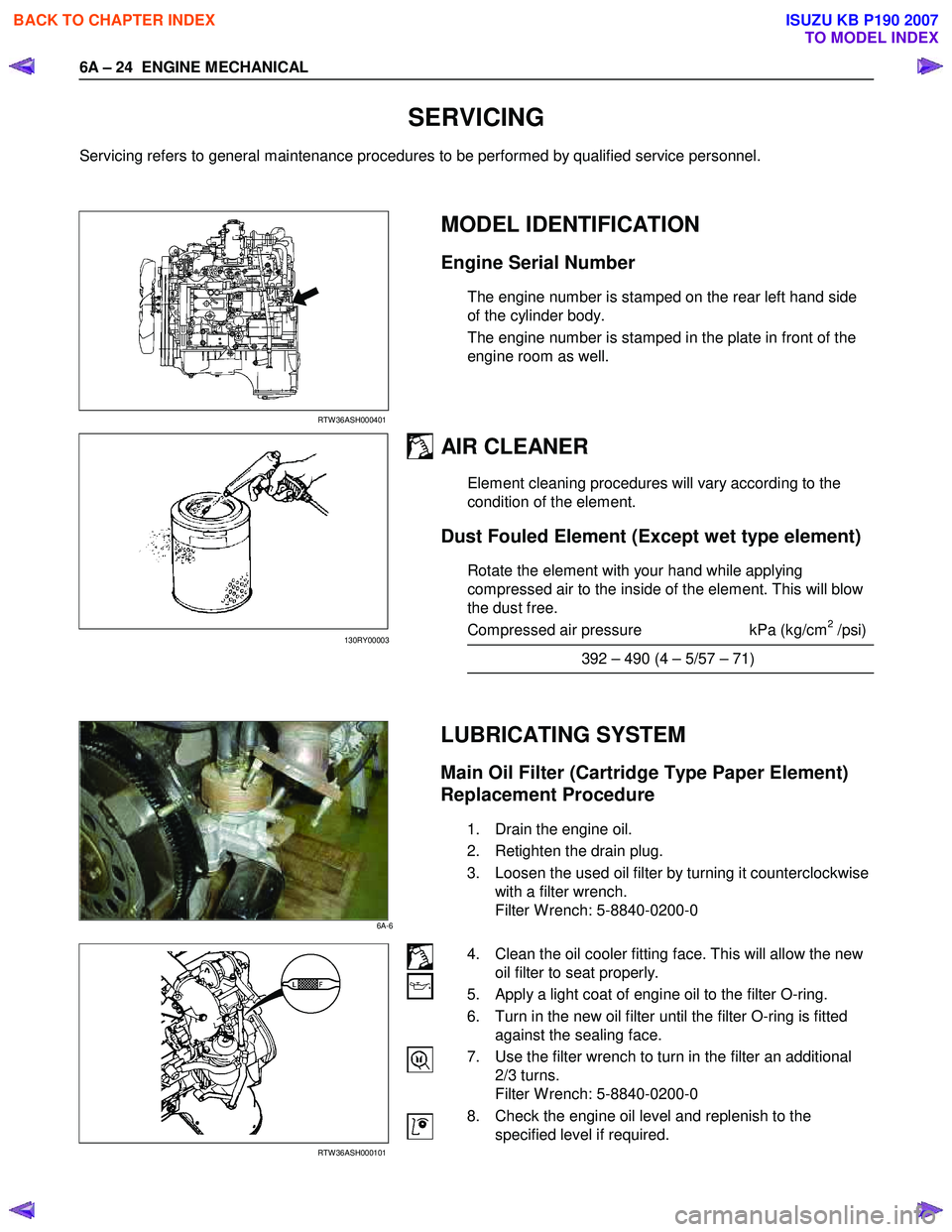
RTW 36ASH000401
MODEL IDENTIFICATION
Engine Serial Number
The engine number is stamped on the rear left hand side
of the cylinder body.
The engine number is stamped in the plate in front of the
engine room as well.
AIR CLEANER
Element cleaning procedures will vary according to the
condition of the element.
Dust Fouled Element (Except wet type element)
Rotate the element with your hand while applying
compressed air to the inside of the element. This will blow
the dust free.
Compressed air pressure kPa (kg/cm
2 /psi)
392 – 490 (4 – 5/57 – 71)
LUBRICATING SYSTEM
Main Oil Filter (Cartridge Type Paper Element)
Replacement Procedure
1. Drain the engine oil.
2. Retighten the drain plug.
3. Loosen the used oil filter by turning it counterclockwise with a filter wrench.
Filter W rench: 5-8840-0200-0
RTW 36ASH000101
4. Clean the oil cooler fitting face. This will allow the new oil filter to seat properly.
5. Apply a light coat of engine oil to the filter O-ring.
6. Turn in the new oil filter until the filter O-ring is fitted against the sealing face.
7. Use the filter wrench to turn in the filter an additional 2/3 turns.
Filter W rench: 5-8840-0200-0
8. Check the engine oil level and replenish to the specified level if required.
130RY00003
6A-6
BACK TO CHAPTER INDEX
TO MODEL INDEX
ISUZU KB P190 2007