fuel pressure ISUZU KB P190 2007 Workshop Manual Online
[x] Cancel search | Manufacturer: ISUZU, Model Year: 2007, Model line: KB P190, Model: ISUZU KB P190 2007Pages: 6020, PDF Size: 70.23 MB
Page 1545 of 6020

6C-4 FUEL SYSTEM (4JK1/4JJ1)
Fuel rail assembly
RTW 76CLF000601
Legend 1. Fuel Pressure Limiter
2. Fuel Rail Pressure Sensor
BACK TO CHAPTER INDEX
TO MODEL INDEX
ISUZU KB P190 2007
Page 1546 of 6020

FUEL SYSTEM (4JK1/4JJ1) 6C-5
Fuel supply pump
RTW 56CLF000301
Legend 1. Fuel Temperature Sensor
2. Suction Control Valve
3. High Pressure Pipe
4. Camshaft Key
5. Camshaft Nut
BACK TO CHAPTER INDEX
TO MODEL INDEX
ISUZU KB P190 2007
Page 1550 of 6020

FUEL SYSTEM (4JK1/4JJ1) 6C-9
Engine does not stop
Condition Possible Cause Correction
Engine does not stop Defective engine control system Diagnose the engine control system.
Exhaust gas is blue or black
Condition Possible Cause Correction
Exhaust gas is blue or black. Reduction in injection-valve opening
pressure or defective atomizing
status Replace the fuel injector.
Engine control system malfunction System diagnosis.
BACK TO CHAPTER INDEX
TO MODEL INDEX
ISUZU KB P190 2007
Page 1551 of 6020
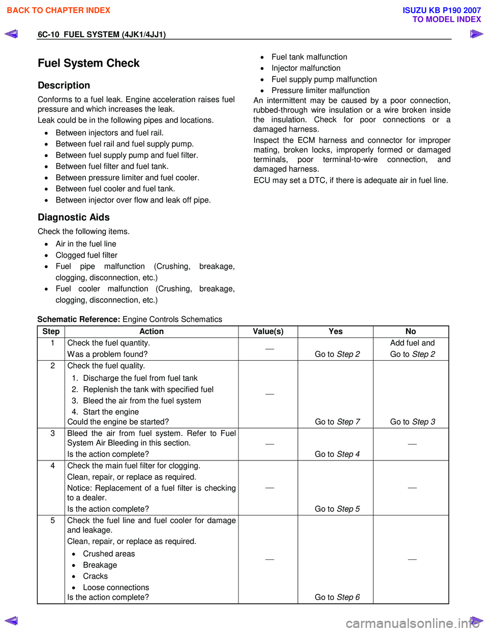
6C-10 FUEL SYSTEM (4JK1/4JJ1)
Fuel System Check
Description
Conforms to a fuel leak. Engine acceleration raises fuel
pressure and which increases the leak.
Leak could be in the following pipes and locations.
• Between injectors and fuel rail.
• Between fuel rail and fuel supply pump.
• Between fuel supply pump and fuel filter.
• Between fuel filter and fuel tank.
• Between pressure limiter and fuel cooler.
• Between fuel cooler and fuel tank.
• Between injector over flow and leak off pipe.
Diagnostic Aids
Check the following items.
• Air in the fuel line
• Clogged fuel filter
• Fuel pipe malfunction (Crushing, breakage,
clogging, disconnection, etc.)
• Fuel cooler malfunction (Crushing, breakage,
clogging, disconnection, etc.)
• Fuel tank malfunction
• Injector malfunction
• Fuel supply pump malfunction
• Pressure limiter malfunction
An intermittent may be caused by a poor connection,
rubbed-through wire insulation or a wire broken inside
the insulation. Check for poor connections or a
damaged harness.
Inspect the ECM harness and connector for imprope
r
mating, broken locks, improperly formed or damaged
terminals, poor terminal-to-wire connection, and
damaged harness.
ECU may set a DTC, if there is adequate air in fuel line.
Schematic Reference: Engine Controls Schematics
Step Action Value(s) Yes No
1 Check the fuel quantity. W as a problem found?
Go to Step 2 Add fuel and
Go to Step 2
2 Check the fuel quality.
1. Discharge the fuel from fuel tank
2. Replenish the tank with specified fuel
3. Bleed the air from the fuel system
4. Start the engine
Could the engine be started?
Go to Step 7 Go to Step 3
3 Bleed the air from fuel system. Refer to Fuel
System Air Bleeding in this section.
Is the action complete?
Go to Step 4
4 Check the main fuel filter for clogging.
Clean, repair, or replace as required.
Notice: Replacement of a fuel filter is checking
to a dealer.
Is the action complete?
Go to Step 5
5 Check the fuel line and fuel cooler for damage
and leakage.
Clean, repair, or replace as required.
• Crushed areas
• Breakage
• Cracks
• Loose connections
Is the action complete?
Go to Step 6
BACK TO CHAPTER INDEX
TO MODEL INDEX
ISUZU KB P190 2007
Page 1560 of 6020

FUEL SYSTEM (4JK1/4JJ1) 6C-19
Fuel Rail Pressure Sensor
Removal
1. Disconnect the fuel pressure sensor harness
connector (1).
LNW 76CSH001601
2. Remove the fuel pressure sensor (2).
Note: Cover the areas exposed during parts removal to
prevent the entry of foreign material into the fuel
system.
RTW 76CSH000101
Legend
1. Fuel Rail
2. Fuel Rail Pressure Sensor
3. Fuel Pressure Limiter
Installation
1. Install the fuel pressure sensor.
Tightening torque: 98 N·m (10.0 kg·m/72 lb ft)
2. Connect the fuel pressure sensor connector.
BACK TO CHAPTER INDEX
TO MODEL INDEX
ISUZU KB P190 2007
Page 1561 of 6020

6C-20 FUEL SYSTEM (4JK1/4JJ1)
Fuel Pressure Limiter
Removal
1. Remove the leak off pipe and hose (1).
Note: Cover the areas exposed during parts removal to
prevent the entry of foreign material into the fuel
system.
RTW 76CSH000301
2. Remove the fuel pressure limiter.
Note: Cover the areas exposed during part removal to
prevent the entry of foreign material into the fuel
system.
RTW 76CSH000101
Legend
1. Fuel Rail
2. Fuel Rail Pressure Sensor
3. Fuel Pressure Limiter
Installation
1. Install the fuel pressure limiter.
Tightening torque: 172 N·m (17.5 kg·m/127 lb ft)
2. Install the fuel leak off pipe and hose using the mounting eyebolt using the specified torque.
Tightening torque: 10 N ⋅
⋅⋅
⋅
m (1.0 kg ⋅
⋅⋅
⋅
m/87 lb in)
BACK TO CHAPTER INDEX
TO MODEL INDEX
ISUZU KB P190 2007
Page 1563 of 6020

6C-22 FUEL SYSTEM (4JK1/4JJ1)
Removal
1. Remove the starter motor.
• Refer to the removal procedure for engine
electricals in this manual.
2. Remove the fuel feed pipe (1) for supply pump.
Note: Cover the areas exposed during parts removal to
prevent the entry of foreign material into the fuel
system.
RTW 76CSH000501
3. Remove the fuel hose (1).
Note: Cover the areas exposed during parts removal to
prevent the entry of foreign material into the fuel
system.
RTW 76CSH000601
4. Remove the leak off pipe and hose (1).
Note: Cover the areas exposed during parts removal to
prevent the entry of foreign material into the fuel
system.
RTW 76CSH000301
5. Disconnect the fuel rail pressure sensor harness
connector (1).
LNW 76CSH001601
BACK TO CHAPTER INDEX
TO MODEL INDEX
ISUZU KB P190 2007
Page 1564 of 6020

FUEL SYSTEM (4JK1/4JJ1) 6C-23
6. Disconnect the injection pipe sleeve nut (1).
Note: Cover the areas exposed during parts removal to
prevent the entry of foreign material into the fuel
system.
RTW 76CSH000701
7. Disconnect the vacuum pipe and swirl control
solenoid valve from the fuel rail bracket.
8. Remove the fuel rail and fuel rail bracket.
Note: • Do not grasp the pressure sensor, during the
fuel rail removal procedure.
• Take care not to damage the connector unit o
f
the pressure sensor.
RTW 76CSH000801
Legend
1. Fuel Rail
2. Fuel Rail Bracket
3. Vacuum Pipe
4. Swirl Control Solenoid Valve
BACK TO CHAPTER INDEX
TO MODEL INDEX
ISUZU KB P190 2007
Page 1565 of 6020

6C-24 FUEL SYSTEM (4JK1/4JJ1)
Disassembly
1. Remove the fuel pressure limiter.
2. Remove the pressure sensor.
RTW 76CSH000101
Legend
1. Fuel Rail
2. Fuel Rail Pressure Sensor
3. Fuel Pressure Limiter
Reassembly
1. Install the fuel pressure limiter.
Tightening torque: 172 N ⋅
⋅⋅
⋅
m (17.5 kg ⋅
⋅⋅
⋅
m/127 lb ft)
2. Install the fuel pressure sensor. Tightening torque: 98 N ⋅
⋅⋅
⋅
m (10.0 kg ⋅
⋅⋅
⋅
m/72 lb ft)
Installation
1. Tighten the fuel rail bracket and fuel rail using the
specified torque.
Tightening torque: 25 N ⋅
⋅⋅
⋅
m (2.5 kg ⋅
⋅⋅
⋅
m/18 lb ft)
2. Tighten the vacuum pipe to the fuel rail bracket using the specified torque.
Tightening torque: 10 N ⋅
⋅⋅
⋅
m (1.0 kg ⋅
⋅⋅
⋅
m/87 lb in)
3. Tighten the swirl control solenoid valve to the fuel rail bracket using the specified torque.
Tightening torque: 20 N ⋅
⋅⋅
⋅
m (2.0 kg ⋅
⋅⋅
⋅
m/14 lb ft)
Note: • Do not grasp the pressure sensor, during the
fuel rail removal procedure.
• Take care not to damage the connector unit o
f
the pressure sensor.
RTW 76CSH000801
Legend
1. Fuel Rail
2. Fuel Rail Bracket
3. Vacuum Pipe
4. Swirl Control Solenoid Valve
4. Tighten the fuel pipe using the mounting sleeve
nut and the specified torque.
Tightening torque: 25 N ⋅
⋅⋅
⋅
m (2.5 kg ⋅
⋅⋅
⋅
m/18 lb ft)
5. Connect the fuel rail pressure sensor harness connector.
BACK TO CHAPTER INDEX
TO MODEL INDEX
ISUZU KB P190 2007
Page 1573 of 6020

6C-32 FUEL SYSTEM (4JK1/4JJ1)
22. Use a gear puller to remove the fuel supply pump
gear.
RTW 56CSH002901
23. Remove the supply pump (1) and supply pump
bracket (2).
• Disconnect the connector of supply pump.
RTW 58ESH002901
Legend
1. Fuel Temperature (FT) Sensor
2. Suction Control Valve (SCV)
Note:
• Do not hold the high pressure pipe, during the
supply pump removal procedure.
• Do not grasp the high pressure pipe, when
moving the supply pump from one location to
another.
RTW 56CSH002001
24. Remove the supply pump and O-ring.
RTW 56CSH002501
Legend
1. O-ring
2. Supply Pump
3. High Pressure Pipe
BACK TO CHAPTER INDEX
TO MODEL INDEX
ISUZU KB P190 2007