stop start ISUZU KB P190 2007 Workshop Repair Manual
[x] Cancel search | Manufacturer: ISUZU, Model Year: 2007, Model line: KB P190, Model: ISUZU KB P190 2007Pages: 6020, PDF Size: 70.23 MB
Page 4940 of 6020

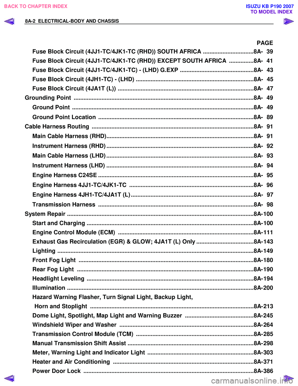
8A-2 ELECTRICAL-BODY AND CHASSIS
PAGE
Fuse Block Circuit (4JJ1-TC/4JK1-TC (RHD)) SOUTH AFRICA ...............................8A- 39
Fuse Block Circuit (4JJ1-TC/4JK1-TC (RHD)) EXCEPT SOUTH AFRICA ...............8A- 41
Fuse Block Circuit (4JJ1-TC/4JK1-TC) - (LHD) G.EXP .............................................8A- 43
Fuse Block Circuit (4JH1-TC) - (LHD) ........................................................................8A- 45
Fuse Block Circuit (4JA1T (L)) ...................................................................................8A- 47
Grounding Point ..............................................................................................................8 A- 49
Ground Point ...............................................................................................................8A- 49
Ground Point Location ...............................................................................................8A- 89
Cable Harness Routing ...................................................................................................8A- 91
Main Cable Harness (RHD)..........................................................................................8A- 91
Instrument Harness (RHD) ..........................................................................................8A- 92
Main Cable Harness (LHD) ..........................................................................................8A- 93
Instrument Harness (LHD) ..........................................................................................8A- 94
Engine Harness C24SE ...............................................................................................8A- 95
Engine Harness 4JJ1-TC/4JK1-TC ............................................................................8A- 96
Engine Harness 4JH1-TC/4JA1T (L) ...........................................................................8A- 97
Transmission Harness ...............................................................................................8A- 98
System Repair ................................................................................................................. .8A- 100
Start and Charging ......................................................................................................8A- 10 0
Engine Control Module (ECM) ...................................................................................8A- 111
Exhaust Gas Recirculation (EGR) & GLOW; 4JA1T (L) Only ...................................8A- 143
Lighting ...................................................................................................................... ..8A- 149
Front Fog Light ...........................................................................................................8A- 180
Rear Fog Light ............................................................................................................8A- 190
Headlight Leveling ......................................................................................................8A- 19 4
Illumination .................................................................................................................. 8A- 200
Hazard Warning Flasher, Turn Signal Light, Backup Light, Horn and Stoplight ....................................................................................................8A- 213
Dome Light, Spotlight, Map Light and Warning Buzzer ..........................................8A- 245
Windshield Wiper and Washer ..................................................................................8A- 264
Transmission Control Module (TCM) ........................................................................8A- 285
Manual Transmission Shift Assist .............................................................................8A- 298
Meter, Warning Light and Indicator Light .................................................................8A- 303
Heater and Air Conditioning ......................................................................................8A- 371
Power Door Lock ........................................................................................................8A- 386
BACK TO CHAPTER INDEX
TO MODEL INDEX
ISUZU KB P190 2007
Page 4971 of 6020

ELECTRICAL-BODY AND CHASSIS 8A-33
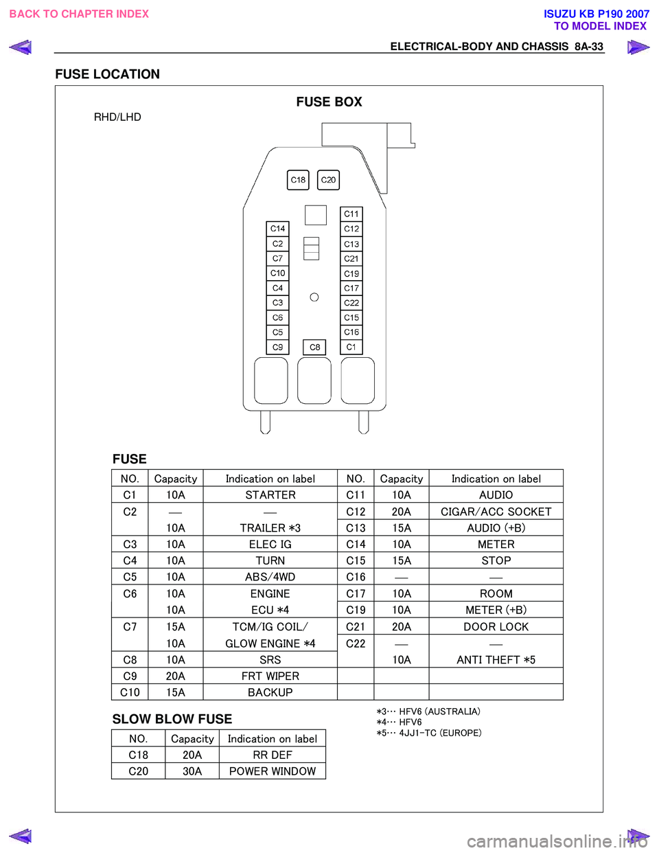
FUSE LOCATION
RHD/LHD
FUSE
NO. Capacity Indication on label NO. Capacity Indication on label
C 1 10A STARTER C 1110A AUDIO
C2
C
12 20A CIGAR/ACC SOCKET
10A TRAILER *3 C 13 15A AUDIO (+B)
C3 10A ELEC IG C 14 10A METER
C4 10A TURN C 15 15A STOP
C5 10A ABS/4WD C 16
C6 10A ENGINE C 17 10A ROOM
10A ECU *4 C19 10A METER (+B)
C7 15A TCM/IG COIL/ C2 120A DOOR LOCK
10A GLOW ENGINE *4 C22
C8 10A SRS 10A ANTI THEFT *5
C9 20A FRT WIPER
C10 15A BACKUP
SLOW BLOW FUSE
NO. Capacity Indication on label
C 18 20A RR DEF
C20 30A POWER WINDOW
FUSE BOX
*3 … HFV6 (AUSTRALIA)
*4 … HFV6
*5 … 4JJ 1-TC (EUROPE)
BACK TO CHAPTER INDEX
TO MODEL INDEXISUZU KB P190 2007
Page 5201 of 6020

ELECTRICAL-BODY AND CHASSIS 8A-263
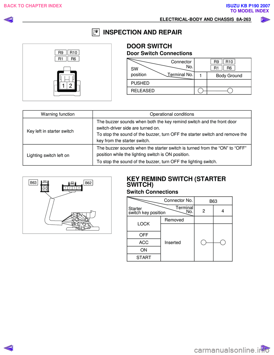
INSPECTION AND REPAIR
R9 R10
R1 R6
DOOR SWITCH
Door Switch Connections
Connector
SW No.
R9
R10
R1 R6
position Terminal No.
1 Body Ground
PUSHED
RELEASED
W arning function Operational conditions
Key left in starter switch The buzzer sounds when both the key remind switch and the front door
switch-driver side are turned on.
To stop the sound of the buzzer, turn OFF the starter switch and remove the
key from the starter switch.
Lighting switch left on The buzzer sounds when the starter switch is turned from the “ON” to “OFF”
position while the lighting switch is ON position.
To stop the sound of the buzzer, turn OFF the lighting switch.
B62 B63
KEY REMIND SWITCH (STARTER
SWITCH)
Switch Connections
Connector
No. B63
Starter Terminal
switch key position No.
2 4
Removed
OFF
ACC Inserted
ON
START
LOCK
BACK TO CHAPTER INDEX TO MODEL INDEXISUZU KB P190 2007
Page 5218 of 6020

8A-280 ELECTRICAL-BODY AND CHASSIS
High Speed Inspection
1. Clamp the wiper motor in a vise.
The moving parts must be clear of the vise.
2. Connect the connector terminals to the battery.
Refer to the illustration.
3. Check the wiper motor high speed operation.
Auto-Stop Inspection
1. Clamp the wiper motor in a vise.
The moving parts must be clear of the vise.
2. Connect the connector terminals to the battery.
Refer to the illustration.
3. Check the wiper motor low speed operation.
4. Disconnect the positive battery terminal.
This will stop the motor.
5. Connect the connector terminals No. 3 and No. 6 with a
lead wire.
Refer to the illustration.
6. Reconnect the positive battery terminal to connecto
r
terminal No. 4.
This will restart the motor.
Refer to the illustration.
7. Check the auto-stop operation.
Washer Motor Inspection
1. Fill the washer tank with washing solution.
2. Disconnect the motor connector.
3. Apply battery voltage to the washer motor connector.
4. Check the washer motor operation.
BACK TO CHAPTER INDEX TO MODEL INDEXISUZU KB P190 2007
Page 5577 of 6020

CRUISE CONTROL SYSTEM 8B-5
Adjustment
1. Check to be sure that the brake pedal has been completely
returned by the return spring.
2. Disconnect the switch connector.
RTW 780SH003301
3. Release the lock 2 by turning the switch 1 counter-clock-
wise.
4. After doing so, pull the pedal arm
3 to you a little so that
the pedal arm is not pushed in.
5. Making the pedal arm not movable with one hand, push in
the whole switch with the other hand until the plunger of the
switch is pushed in and the switch itself hits the rubber o
f
the pedal arm.
In the condition, turn the switch clock-wise until "click"
sound is made and lock it.
By doing this, the switch is adjusted at 0.2 to 1.2mm (0.01-
0.06 in) clearance.
Clutch Switch
Removal and Installation
Refer to the Clutch Control removal and installation procedure
in Clutch section.
Adjustment
1. Turn the clutch switch or stopper bolt 1 until the switch bolt
or stopper bolt just touches the clutch pedal arm.
2.
Adjust clutch switch or stopper bolt by backing it out half a
turn, and measure the clearance (L) between the clutch
pedal arm and the clutch switch bolt end or stopper bolt.
3. Lock the lock nut
2.
4. Connect the clutch switch connector.
Clutch switch and clutch pedal clearance
mm (in)
Clearance 0.5-1.5 (0.020-0.059)
Starter Switch
431R300001
Removal and Installation
Refer to the Starter Switch removal and installation procedure
of Start and Charging in Body and Chassis section.
BACK TO CHAPTER INDEX
TO MODEL INDEXISUZU KB P190 2007
Page 5909 of 6020

IMMOBILIZER SYSTEM (C24SE, 4JA1-T) 11A-11
Immobilizer control unit (ICU);
Mechanical Control Engine (4JA1-T)
Immobilizer control unit (ICU) permits engine starting,
when the security code which compares the securit
y
code registered into the transponder (key) and the
security code registered into ICU, and is similarl
y
registered into ICU and engine immobilizer unit (DDS-1)
is compared and it is judged that it is normal. W hen the
code registered into the key is unusual, and when not
recognizing a security code, engine immobilizer unit
does not permit starting of engine by the fuel cut valve
on the fuel pump.
The engine immobilizer unit is located with fuel cut
valve on fuel pump 4JA1-T engine.
The immobilizer control unit decides whether there is an
abnormality the security code based on the engine
immobilizer unit security code.
W hen the problem found, the engine immobilizer unit
stops fuel supply by the fuel cut valve.
RAW 4B0SF000101
BACK TO CHAPTER INDEX
TO MODEL INDEX
ISUZU KB P190 2007