ECU ISUZU KB P190 2007 Workshop Repair Manual
[x] Cancel search | Manufacturer: ISUZU, Model Year: 2007, Model line: KB P190, Model: ISUZU KB P190 2007Pages: 6020, PDF Size: 70.23 MB
Page 2090 of 6020

6A-76 ENGINE MECHANICAL (C24SE)
Spark Plug Thread
Recondition
Ream thread and recut using commercially available spark
plug thread drill (observe manufacturer's instructions).
Removal
Remove thread bush on spark plug. (dimensions (A) =
17mm/0.67in.)
Tighten (Torque)
Spark plug with thread bush into cylinder head - 25N ⋅m (2.5
kgf ⋅m) - use.
BACK TO CHAPTER INDEX
TO MODEL INDEX
ISUZU KB P190 2007
Page 2129 of 6020

ENGINE FUEL (C24SE) 6C-11
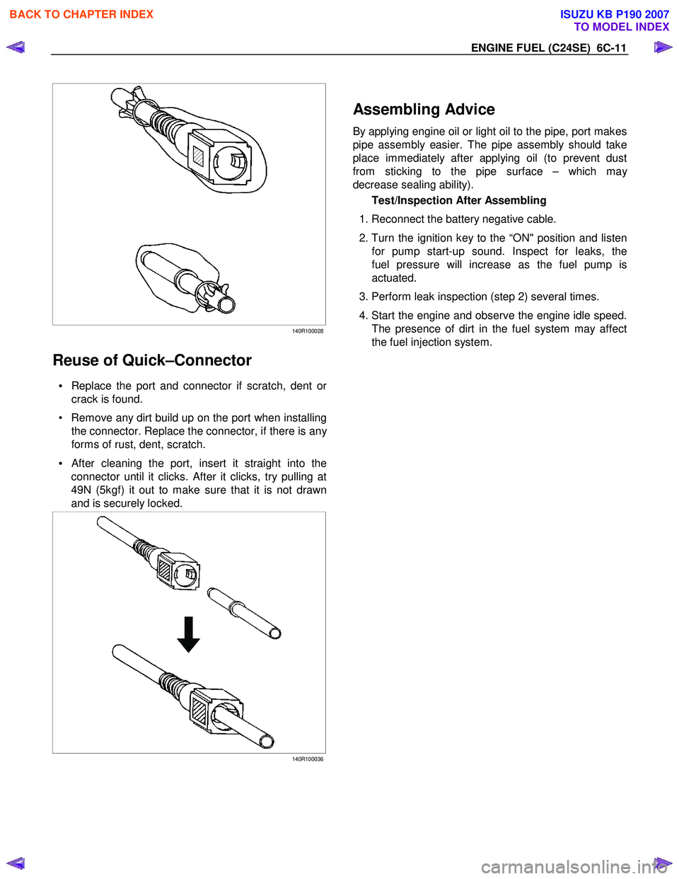
140R100028
Reuse of Quick–Connector
• Replace the port and connector if scratch, dent or
crack is found.
• Remove any dirt build up on the port when installing the connector. Replace the connector, if there is an
y
forms of rust, dent, scratch.
•
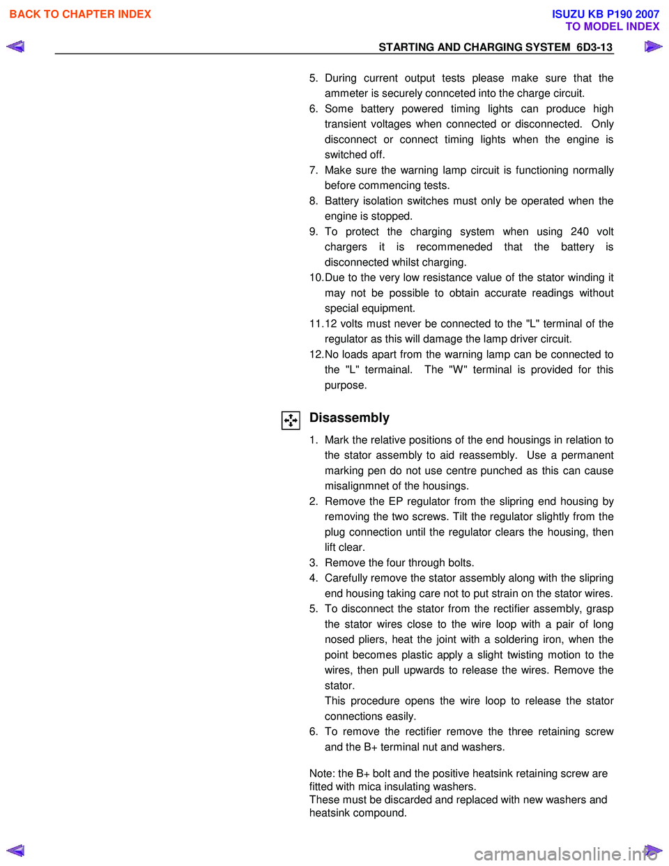
After cleaning the port, insert it straight into the
connector until it clicks. After it clicks, try pulling at
49N (5kgf) it out to make sure that it is not drawn
and is securely locked.
140R100036
Assembling Advice
By applying engine oil or light oil to the pipe, port makes
pipe assembly easier. The pipe assembly should take
place immediately after applying oil (to prevent dust
from sticking to the pipe surface – which ma
y
decrease sealing ability).
Test/Inspection After Assembling
1. Reconnect the battery negative cable.
2. Turn the ignition key to the “ON" position and listen
for pump start-up sound. Inspect for leaks, the
fuel pressure will increase as the fuel pump is
actuated.
3. Perform leak inspection (step 2) several times.
4. Start the engine and observe the engine idle speed.
The presence of dirt in the fuel system may affect
the fuel injection system.
BACK TO CHAPTER INDEX
TO MODEL INDEX
ISUZU KB P190 2007
Page 2161 of 6020

STARTING AND CHARGING SYSTEM 6D3-13
5. During current output tests please make sure that the
ammeter is securely connceted into the charge circuit.
6. Some battery powered timing lights can produce high transient voltages when connected or disconnected. Onl
y
disconnect or connect timing lights when the engine is
switched off.
7. Make sure the warning lamp circuit is functioning normall
y
before commencing tests.
8. Battery isolation switches must only be operated when the engine is stopped.
9. To protect the charging system when using 240 volt chargers it is recommeneded that the battery is
disconnected whilst charging.
10. Due to the very low resistance value of the stator winding it may not be possible to obtain accurate readings without
special equipment.
11. 12 volts must never be connected to the "L" terminal of the regulator as this will damage the lamp driver circuit.
12. No loads apart from the warning lamp can be connected to the "L" termainal. The "W " terminal is provided for this
purpose.
Disassembly
1. Mark the relative positions of the end housings in relation to the stator assembly to aid reassembly. Use a permanent
marking pen do not use centre punched as this can cause
misalignmnet of the housings.
2. Remove the EP regulator from the slipring end housing b
y
removing the two screws. Tilt the regulator slightly from the
plug connection until the regulator clears the housing, then
lift clear.
3. Remove the four through bolts.
4. Carefully remove the stator assembly along with the slipring end housing taking care not to put strain on the stator wires.
5. To disconnect the stator from the rectifier assembly, grasp the stator wires close to the wire loop with a pair of long
nosed pliers, heat the joint with a soldering iron, when the
point becomes plastic apply a slight twisting motion to the
wires, then pull upwards to release the wires. Remove the
stator.
This procedure opens the wire loop to release the stato
r
connections easily.
6. To remove the rectifier remove the three retaining scre
w
and the B+ terminal nut and washers.
Note: the B+ bolt and the positive heatsink retaining screw are
fitted with mica insulating washers.
These must be discarded and replaced with new washers and
heatsink compound.
BACK TO CHAPTER INDEX
TO MODEL INDEX
ISUZU KB P190 2007
Page 2172 of 6020

6E–2 ENGINE DRIVEABILITY AND EMISSIONS
5e. Vehicle Operates as Designed ............ 6E-65
6. Re-examine the complaint ..................... 6E-66
7. Repair and Verify Fix ............................. 6E-66
GENERAL SERVICE INFORMATION .......... 6E-67 On-Board Diagnostic (OBD) ...................... 6E-68
On-Board Diagnostic Tests ....................... 6E-68
The Diagnostic Executive .......................... 6E-68
Diagnostic Information ............................... 6E-68
Check Engine Lamp .................................. 6E-68
Data Link Connector (DLC) ....................... 6E-68
Tech 2 Operating Flow Cart (Start Up) ...... 6E-70
TYPICAL SCAN DATA & DEFINITIONS (ENGINE DATA) ......................................... 6E-72
TYPICAL SCAN DATA & DEFINITIONS (O2 SENSOR DATA) .................................. 6E-74
MISCELLANEOUS TEST ............................. 6E-76
PLOTTING SNAPSHOT GRAPH ................. 6E-78 Plotting Graph Flow Chart (Plotting graph after obtaining vehicle information) .................. 6E-79
Flow Chart for Snapshot Replay (Plotting Graph) ....................................... 6E-80
SNAPSHOT DISPLAY WITH TIS2000 ......... 6E-81
ON-BOARD DIAGNOSTIC (OBD) SYSTEM CHECK 6E-98
Circuit Description ......................................... 6E-90
Diagnostic Aids ............................................. 6E-90
Test Description ............................................ 6E-90
ON-BOARD DIAGNOSTIC (OBD) SYSTEM CHECK .................................................... 6E-91
NO CHECK ENGINE LAMP (MIL) ................ 6E-94 Circuit Description ..................................... 6E-94
Diagnostic Aids .......................................... 6E-94
No Check Engine Lamp (MIL) ................... 6E-94
CHECK ENGINE LAMP (MIL) “ON” STEADY 6E-96 Circuit description ...................................... 6E-96
Diagnostic Aids .......................................... 6E-96
Check Engine Lamp (MIL) “ON” Steady .... 6E-96
FUEL METERING SYSTEM CHECK ........... 6E-98
FUEL INJECTOR COIL TEST PROCEDURE AND FUEL INJECTOR BALANCE TEST
PROCEDURE ............................................. 6E-98
Test Description ......................................... 6E-98
Injector Coil Test Procedure (Steps 1-6) and Injector Balance Test Procedure
(Steps 7-11) ............................................. 6E-99
Injector Coil Test Procedure (Steps 1-6) and Injector Balance Test Procedure
(Steps 7-11) ............................................. 6E-100
FUEL SYSTEM ELECTRICAL TEST ........... 6E-103 Circuit Description ..................................... 6E-103
Diagnostic Aids .......................................... 6E-104 Fuel Pressure Relief Procedure ................. 6E-104
Fuel Pressure Gauge Installation .............. 6E-104
Fuel System Electrical Test ....................... 6E-104
FUEL SYSTEM DIAGNOSIS ........................ 6E-108 Circuit Description ...................................... 6E-108
Test Description ......................................... 6E-108
Fuel Pressure Relief Procedure ................. 6E-109
Fuel Pressure Gauge Installation .............. 6E-109
Fuel System Diagnosis .............................. 6E-110
ECM DIAGNOSTIC TROUBLE CODES (DTC) 6E-113
DIAGNOSTIC TROUBLE CODE (DTC) P0107 MANIFOLD ABSOLUTE PRESSURE
CIRCUIT LOW INPUT ................................ 6E-119
Circuit Description ...................................... 6E-119
Diagnostic Aids .......................................... 6E-119
Diagnostic Trouble Code (DTC) P0107 Manifold Absolute Pressure Circuit Low
Input ......................................................... 6E-120
DIAGNOSTIC TROUBLE CODE (DTC) P0108 MANIFOLD ABSOLUTE PRESSURE
CIRCUIT HIGH INPUT ............................... 6E-123
Circuit Description ...................................... 6E-123
Diagnostic Aids .......................................... 6E-124
Diagnostic Trouble Code (DTC) P0108 Manifold Absolute Pressure Circuit High
Input ......................................................... 6E-124
DIAGNOSTIC TROUBLE CODE (DTC) P0112 INTAKE AIR TEMPERATURE SENSOR LOW
INPUT ......................................................... 6E-127
Circuit Description ...................................... 6E-127
Diagnostic Aids .......................................... 6E-127
Diagnostic Trouble Code (DTC) P0112 Intake Air Temperature Sensor Low Input 6E-128
DIAGNOSTIC TROUBLE CODE (DTC) P0113 INTAKE AIR TEMPERATURE SENSOR HIGH
INPUT ......................................................... 6E-131
Circuit Description ...................................... 6E-131
Diagnostic Aids .......................................... 6E-131
Diagnostic Trouble Code (DTC) P0113 Intake Air Temperature Sensor High Input 6E-132
DIAGNOSTIC TROUBLE CODE (DTC) P0117 ENGINE COOLANT TEMPERATURE
SENSOR LOW INPUT ................................ 6E-136
Circuit Description ...................................... 6E-136
Diagnostic Aids .......................................... 6E-136
Diagnostic Trouble Code (DTC) P0117 Engine Coolant Temperature Sensor Low
Input ......................................................... 6E-137
DIAGNOSTIC TROUBLE CODE (DTC) P0118 ENGINE COOLANT TEMPERATURE
SENSOR HIGH INPUT ............................... 6E-139
Circuit Description ...................................... 6E-139
BACK TO CHAPTER INDEX
TO MODEL INDEX
ISUZU KB P190 2007
Page 2174 of 6020

6E–4 ENGINE DRIVEABILITY AND EMISSIONS
DIAGNOSTIC TROUBLE CODE (DTC) P0443 EVAPORATIVE (EVAP) EMISSION CONTROL
SYSTEM PURGE CONTROL CIRCUIT ..... 6E-191
Circuit Description ..................................... 6E-191
Diagnostic Aids .......................................... 6E-191
Diagnostic Trouble Code (DTC) P0443 EVAP Emission Control System Purge
Control Circuit .......................................... 6E-192
DIAGNOSTIC TROUBLE CODE (DTC) P0502 VEHICLE SPEED SENSOR (VSS) CIRCUIT
LOW INPUT ................................................ 6E-195
Circuit Description ..................................... 6E-195
Diagnostic Aids .......................................... 6E-195
Diagnostic Trouble Code (DTC) P0502 Vehicle Speed Sensor Circuit Low Input . 6E-196
DIAGNOSTIC TROUBLE CODE (DTC) P0562 SYSTEM VOLTAGE LOW .......................... 6E-202
Circuit Description ..................................... 6E-202
Diagnostic Aids .......................................... 6E-202
Diagnostic Trouble Code (DTC) P0562 System Voltage Low ............................................. 6E-202
DIAGNOSTIC TROUBLE CODE (DTC) P0563 SYSTEM VOLTAGE HIGH ......................... 6E-204
Circuit Description ..................................... 6E-204
Diagnostic Aids .......................................... 6E-204
Diagnostic Trouble Code (DTC) P0563 System Voltage High ............................................ 6E-204
DIAGNOSTIC TROUBLE CODE (DTC) P0601 ECM MEMORY CHECKSUM ..................... 6E-206
Circuit Description ..................................... 6E-206
Diagnostic Aids .......................................... 6E-206
Diagnostic Trouble Code (DTC) P0601 ECM Memory Checksum .................................. 6E-206
DIAGNOSTIC TROUBLE CODE (DTC) P0602 ECU PROGRAMMING ERROR ................. 6E-207
Circuit Description ..................................... 6E-207
Diagnostic Aids .......................................... 6E-207
Diagnostic Trouble Code (DTC) P0602 ECU Programming Error .................................. 6E-207
DTC P0650 MALFUNCTION INDICATOR LAMP (MIL) CONTOROL CIRCUIT MALFUNCTION 6E-208
Circuit Description ..................................... 6E-208
Diagnostic Aids .......................................... 6E-208
Diagnostic Trouble Code (DTC) P0650 Malfunction Indicator Lamp (MIL) Control
Circuit Malfunction ................................... 6E-209
DIAGNOSTIC TROUBLE CODE (DTC) P1167 FUEL SUPPLY SYSTEM RICH DURING
DECELERATION FUEL CUT OFF ............. 6E-211
Circuit Description ..................................... 6E-211
Diagnostic Aids .......................................... 6E-211
Diagnostic Trouble Code (DTC) P1167 Fuel Supply System Rich During
Deceleration Fuel Cutoff .......................... 6E-212
DIAGNOSTIC TROUBLE CODE (DTC) P1171 FUEL SUPPLY SYSTEM LEAN DURING
POWER ENRICHMENT ............................. 6E-214
Circuit Description ...................................... 6E-214
Diagnostic Aids .......................................... 6E-215
Diagnostic Trouble Code (DTC) P1171 Fuel Supply System Lean During Power
Enrichment .............................................. 6E-215
DIAGNOSTIC TROUBLE CODE (DTC) P1625 ECM SYSTEM RESET ............................... 6E-217
Circuit Description ...................................... 6E-217
Diagnostic Aids .......................................... 6E-217
Diagnostic Trouble Code (DTC) P1625 ECM System Reset .......................................... 6E-217
DIAGNOSTIC TROUBLE CODE (DTC) P1626 IMMOBILIZER NO SIGNAL ........................ 6E-218
Circuit Description ...................................... 6E-218
Diagnostic Aids .......................................... 6E-218
Diagnostic Trouble Code (DTC) P1626 Immobilizer No Signal .............................. 6E-219
DIAGNOSTIC TROUBLE CODE (DTC) P1631 IMMOBILIZER WRONG SIGNAL ............... 6E-222
Circuit Description ...................................... 6E-222
Diagnostic Aids .......................................... 6E-222
Diagnostic Trouble Code (DTC) P1631 Immobilizer Wrong Signal ........................ 6E-223
DIAGNOSTIC TROUBLE CODE (DTC) P1648 WRONG SECURITY CODE ENTERED .. 6E-224
Circuit Description ...................................... 6E-224
Diagnostic Aids .......................................... 6E-224
Diagnostic Trouble Code (DTC) P1648 Wrong Security Code Entered ............................ 6E-225
DIAGNOSTIC TROUBLE CODE (DTC) P1649 IMMOBILIZER FUNCTION NOT
PROGRAMMED ......................................... 6E-226
Circuit Description ...................................... 6E-226
Diagnostic Aids .......................................... 6E-226
Diagnostic Trouble Code (DTC) P1649 Immobilizer Function Not Programmed ... 6E-227
DIAGNOSTIC TROUBLE CODE (DTC) P1693 TACHOMETER OUTPUT LOW VOLTAGE 6E-228
Circuit Description ...................................... 6E-228
Diagnostic Aids .......................................... 6E-228
Diagnostic Trouble Code (DTC) P1693 Tachometer Output Low Voltage ............. 6E-229
SYMPTOM DIAGNOSIS ............................... 6E-232
PRELIMINARY CHECKS ............................. 6E-232
VISUAL/PHYSICAL CHECK ......................... 6E-232
INTERMITTENT ........................................... 6E-232
BACK TO CHAPTER INDEX
TO MODEL INDEX
ISUZU KB P190 2007
Page 2236 of 6020

6E–66 ENGINE DRIVEABILITY AND EMISSIONS
• Vehicle service information (service manual, etc.)
• ISUZU field support
• Experience
• Identical vehicle or system for comparison
6. Re-examine the complaint
When you do not successfully find/isolate the problem
after executing a diagnostic path, you should re-
examine the complaint.
What you should do
In this case, you will need to backtrack and review
information accumulated from step 1 through 4 of
Strategy Based Diagnostics. You also should repeat any
procedures that require additional attention.
A previous path may be eliminated from consideration
only if you are certain that all steps were executed as
directed. You must then select another diagnostic path
(step 5a, 5b, 5c or 5d). If all possible options have been
explored, you may call or seek ISUZU field support.
What resources you should use
Whenever possible, you should use the following
resources to facilitate the diagnostic process:
• Service manual
• Accumulated information form a previous diagnostic path
• Service information and publications
• ISUZU field support
7. Repair and Verify Fix
What you should do
After you have located the cause of the problem, you
must execute a repair by following recommended
service manual procedures.
When the repair is completed, you should verify the fix
by performing the system checks under the conditions
listed in the customer complaint.
If applicable, you should carry out preventive measures
to avoid a repeat complaint.
What resources you should use
Whenever possible, you should use the following
resources to facilitate the repair process:
• Electrical repair procedures
• Service manual information and publications
BACK TO CHAPTER INDEX
TO MODEL INDEX
ISUZU KB P190 2007
Page 2238 of 6020

6E–68 ENGINE DRIVEABILITY AND EMISSIONS
On-Board Diagnostic (OBD)
On-Board Diagnostic Tests
A diagnostic test is a series of steps, the result of which
is a pass or fail reported to the diagnostic executive.
When a diagnostic test reports a pass result, the
diagnostic executive records the following data:
• The diagnostic test has been completed since the last ignition cycle.
• The diagnostic test has passed during the current ignition cycle.
• The fault identified by the diagnostic test is not currently active.
When a diagnostic test reports a fail result, the
diagnostic executive records the following data:
• The diagnostic test has been completed since the last ignition cycle.
• The fault identified by the diagnostic test is currently active.
• The fault has been active during this ignition cycle.
• The operating conditions at the time of the failure.
The Diagnostic Executive
The Diagnostic Executive is a unique segment of
software which is designed to coordinate and prioritize
the diagnostic procedures as well as define the protocol
for recording and displaying their results. The main
responsibilities of the Diagnostic Executive are listed as
follows:
• Commanding the check engine lamp on and off
• DTC logging and clearing
• Current status information on each diagnostic
Diagnostic Information
The diagnostic charts and functional checks are
designed to locate a faulty circuit or component through
a process of logical decisions. The charts are prepared
with the requirement that the vehicle functioned
correctly at the time of assembly and that there are not
multiple faults present.
There is a continuous self-diagnosis on certain control
functions. This diagnostic capability is complemented
by the diagnostic procedures contained in this manual.
The language of communicating the source of the
malfunction is a system of diagnostic trouble codes.
When a malfunction is detected by the control module, a
diagnostic trouble code is set and the check engine
lamp is illuminated.
Check Engine Lamp
The check engine lamp looks the same as the check
engine lamp you are already familiar with, the “Check
Engine” lamp.
Basically, the check engine lamp is turned on when the
ECM detects a DTC that will impact the vehicle
emissions.
• When the check engine lamp remains “ON” while the engine is running, or when a malfunction is suspected due to a driveability or emissions problem,
a Powertrain On-Board Diagnostic (OBD) System
Check must be performed. The procedures for these
checks are given in On-Board Diagnostic (OBD)
System Check. These checks will expose faults
which may not be detected if other diagnostics are
performed first.
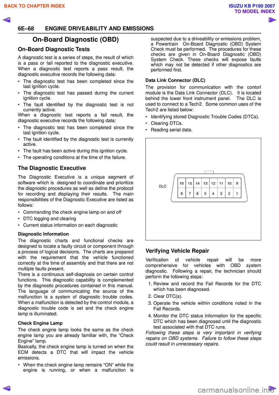
Data Link Connector (DLC)
The provision for communication with the contorl
module is the Data Link Connector (DLC). It is located
behind the lower front instrument panel. The DLC is
used to connect to a Tech 2. Some common uses of the
Tech 2 are listed below:
• Identifying stored Diagnostic Trouble Codes (DTCs).
• Clearing DTCs.
• Reading serial data.
Verifying Vehicle Repair
Verification of vehicle repair will be more
comprehensive for vehicles with OBD system
diagnostic. Following a repair, the technician should
perform the following steps:
1. Review and record the Fail Records for the DTC which has been diagnosed.
2. Clear DTC(s).
3. Operate the vehicle within conditions noted in the Fail Records.
4. Monitor the DTC status information for the specific DTC which has been diagnosed until the diagnostic
test associated with that DTC runs.
Following these steps is very important in verifying
repairs on OBD systems. Failure to follow these steps
could result in unnecessary repairs.
BACK TO CHAPTER INDEX
TO MODEL INDEX
ISUZU KB P190 2007
Page 2251 of 6020
![ISUZU KB P190 2007 Workshop Repair Manual ENGINE DRIVEABILITY AND EMISSIONS 6E–81
SNAPSHOT DISPLAY WITH TIS2000
Procedures for transferring and displaying Tech2
snapshot data by using TIS2000 [Snapshot Upload]
function is described below.
ISUZU KB P190 2007 Workshop Repair Manual ENGINE DRIVEABILITY AND EMISSIONS 6E–81
SNAPSHOT DISPLAY WITH TIS2000
Procedures for transferring and displaying Tech2
snapshot data by using TIS2000 [Snapshot Upload]
function is described below.](/img/61/57177/w960_57177-2250.png)
ENGINE DRIVEABILITY AND EMISSIONS 6E–81
SNAPSHOT DISPLAY WITH TIS2000
Procedures for transferring and displaying Tech2
snapshot data by using TIS2000 [Snapshot Upload]
function is described below.
Snapshot data can be displayed with [Snapshot Upload]
function included in TIS2000.
1. Record the snapshot data, in Tech2.
2. Transfer the snapshot data to PC. By analyzing these data in various methods, trouble
conditions can be checked.
Snapshot data is displayed by executing the three steps
below shown:
After recording the snapshot in Tech2, transfer the data
from Tech2 to PC by the below procedures.
1. Start TIS2000.
2. Select [Snapshot Upload] on the TIS2000 start screen.
3. Select [Upload from trouble diagnosis tool (transfer from diagnosis tester)] or click the corresponding
icon of the tool bar.
4. Select Tech2, and transfer the recorded snapshot information. 5. Select the transferred snapshot.
6. After ending transfer of the snapshot, data parameter list is displayed on the screen.
BACK TO CHAPTER INDEX
TO MODEL INDEX
ISUZU KB P190 2007
Page 2256 of 6020

6E–86 ENGINE DRIVEABILITY AND EMISSIONS
5. After choosing the data, click the “Next” button.
6. When all the necessary information is entered, the “details” of software within the database that match
the entered data will appear for confirmation. Click
the “Program” switch and then download the new
software onto Tech-2.
7. “Data Transfer” comes on display. The progress of downloading will be displayed on the screen in the
form of bar graph.
8. Upon finishing the data transfer, turn off the power of Tech-2, removing from P/C. 4. Programming of ECM
1. Check to see if batteries are fully charged, while ABS connectors shall be removed from the vehicle.
2. Connect Tech-2 to Vehicle Diagnostic Connectors.
3. Turn on the power of Tech-2 and the title screen comes on display.
4. Turn on the ignition (without allowing the engine to start)
5. On the title screen of Tech-2, push the “Enter” button.
6. Choose “F1: Service Programming System” on the main screen and then choose “Fl: Program ECU”.
7. While data is being transferred, “Programming in Progress” will be displayed on the Tech-2 screen.
8. Upon finishing the data transfer, Tech-2 will display “Reprogramming Was Successful”. Push the “Exit”
button to bring program to completion
9. Following “Procedure 2: Demand of Data”, try over again “Information Obtaining” and check to confirm
if the data has been correctly re-loaded.
10. Upon finishing confirmation, turn off the ignition of the vehicle and then turn off the power of Tech-2,
removing from the vehicle.
BACK TO CHAPTER INDEX
TO MODEL INDEX
ISUZU KB P190 2007
Page 2283 of 6020

ENGINE DRIVEABILITY AND EMISSIONS 6E–113
ECM DIAGNOSTIC TROUBLE CODES (DTC)Ty p e A
•Emission related.
• Requests illumination of the MIL (Malfunction Indicator Lamp = Check Engine Lamp) of the first trip with a fail.
• Stores a history DTC on the first trip.
• Stores a freeze frame (If empty).
• Stores a fail record.
• Updates the fail record each time the diagnostic test fails.
Ty p e B
•Emission related.
• “Armed” after one trip with fail.
• “Disarmed” after one trip with a pass.
• Requests illumination of the MIL on the second consecutive trip with a fail.
• Store a history DTC on the second consecutive trip with a fail. (The DTC will be armed after the first fail.)
• Stores a freeze frame on the second consecutive trip with a fail (If empty).
• Stores a fail record when the first test fails (not dependent on consecutive trip).
• Updates the fail record each time the diagnostic test fails.
Ty p e D
• Non emission related.
• Does not request illumination of any lamp.
• Stores a history DTC on the first trip.
• Does not store a freeze frame.
• Stores fail record when test fails.
• Updates the fail record each time the diagnostic test fails.
BACK TO CHAPTER INDEX
TO MODEL INDEX
ISUZU KB P190 2007