Fuel line ISUZU KB P190 2007 Workshop Repair Manual
[x] Cancel search | Manufacturer: ISUZU, Model Year: 2007, Model line: KB P190, Model: ISUZU KB P190 2007Pages: 6020, PDF Size: 70.23 MB
Page 3229 of 6020
Fuel System – V6 Page 6C – 27
4.6 Evaporative Emission Control Canister
Remove
1 Raise the vehicle on a hoist to give access to the evaporative emission control canister, located above the spare
wheel , refer to 0A General Information.
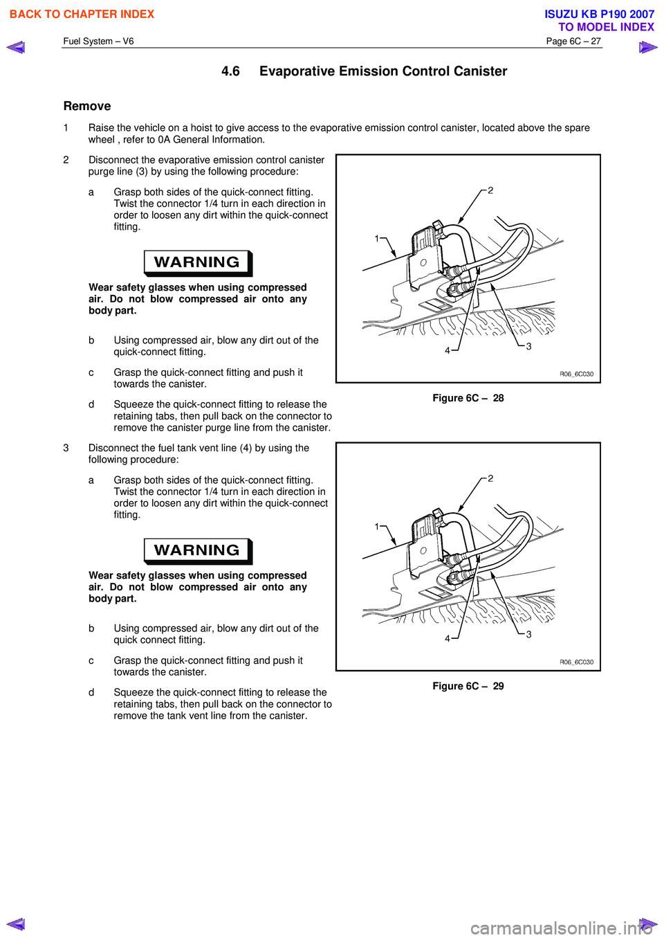
2 Disconnect the evaporative emission control canister purge line (3) by using the following procedure:
a Grasp both sides of the quick-connect fitting. Twist the connector 1/4 turn in each direction in
order to loosen any dirt within the quick-connect
fitting.
Wear safety glasses when using compressed
air. Do not blow compressed air onto any
body part.
b Using compressed air, blow any dirt out of the quick-connect fitting.
c Grasp the quick-connect fitting and push it towards the canister.
d Squeeze the quick-connect fitting to release the retaining tabs, then pull back on the connector to
remove the canister purge line from the canister.
Figure 6C – 28
3 Disconnect the fuel tank vent line (4) by using the following procedure:
a Grasp both sides of the quick-connect fitting. Twist the connector 1/4 turn in each direction in
order to loosen any dirt within the quick-connect
fitting.
Wear safety glasses when using compressed
air. Do not blow compressed air onto any
body part.
b Using compressed air, blow any dirt out of the quick connect fitting.
c Grasp the quick-connect fitting and push it towards the canister.
d Squeeze the quick-connect fitting to release the retaining tabs, then pull back on the connector to
remove the tank vent line from the canister.
Figure 6C – 29
BACK TO CHAPTER INDEX
TO MODEL INDEX
ISUZU KB P190 2007
Page 3230 of 6020
Fuel System – V6 Page 6C – 28
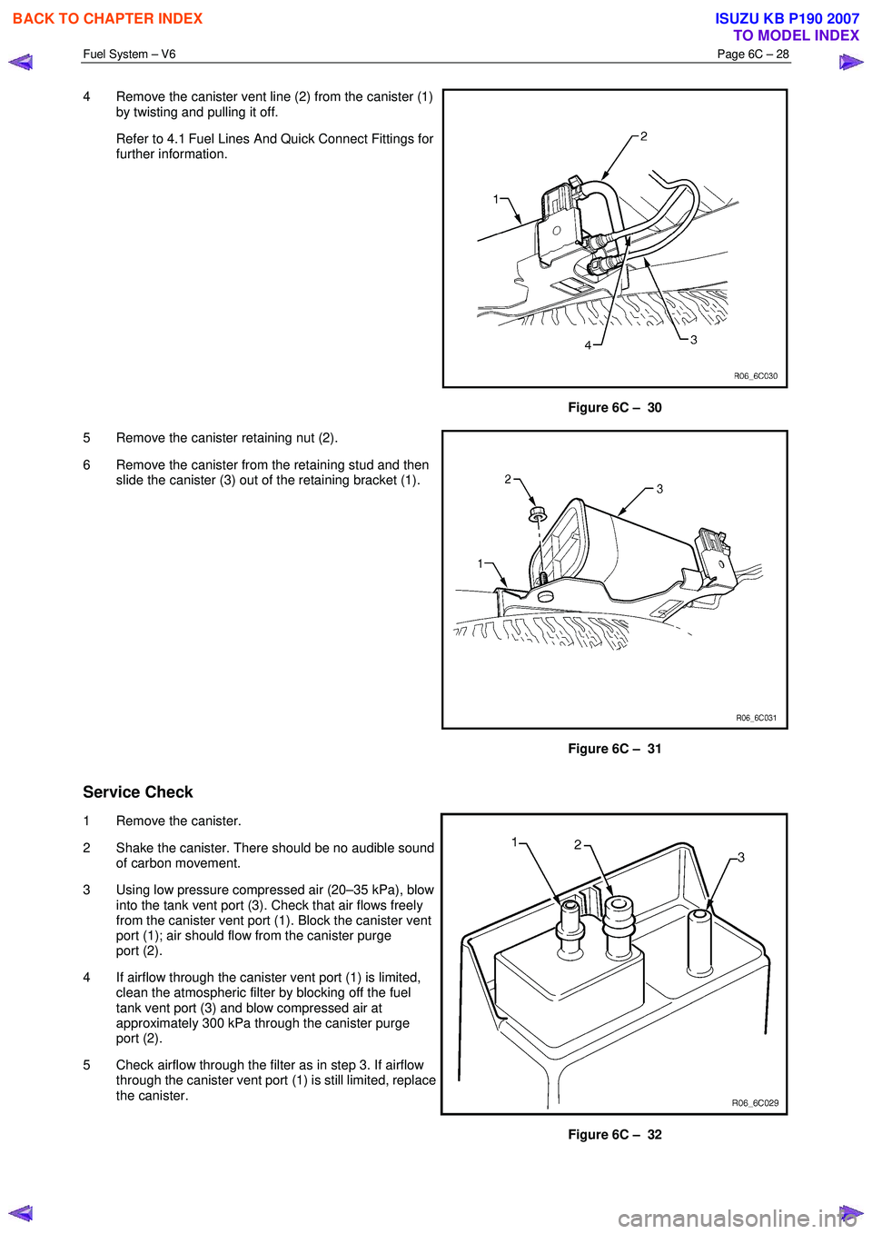
4 Remove the canister vent line (2) from the canister (1)
by twisting and pulling it off.
Refer to 4.1 Fuel Lines And Quick Connect Fittings for further information.
Figure 6C – 30
5 Remove the canister retaining nut (2).
6 Remove the canister from the retaining stud and then slide the canister (3) out of the retaining bracket (1).
Figure 6C – 31
Service Check
1 Remove the canister.
2 Shake the canister. There should be no audible sound of carbon movement.
3 Using low pressure compressed air (20–35 kPa), blow into the tank vent port (3). Check that air flows freely
from the canister vent port (1). Block the canister vent
port (1); air should flow from the canister purge
port (2).
4 If airflow through the canister vent port (1) is limited, clean the atmospheric filter by blocking off the fuel
tank vent port (3) and blow compressed air at
approximately 300 kPa through the canister purge
port (2).
5 Check airflow through the filter as in step 3. If airflow through the canister vent port (1) is still limited, replace
the canister.
Figure 6C – 32
BACK TO CHAPTER INDEX
TO MODEL INDEX
ISUZU KB P190 2007
Page 3231 of 6020
Fuel System – V6 Page 6C – 29
6 Block the canister vent port (1) and the canister purge port (2). Apply low-pressure compressed air
(20–35 kPa) to the tank vent port (3). If any air leaks from the canister (that is, around the ports or seams), replace
the canister.
NOTE
In dusty areas, an alternative is to block the
canister purge port (2). Blow air through the
canister vent (1) port and check that air is
expelled through the tank vent port (3).
Reinstall
Reinstallation of the evaporative emission control canister is the reverse of the removal procedure.
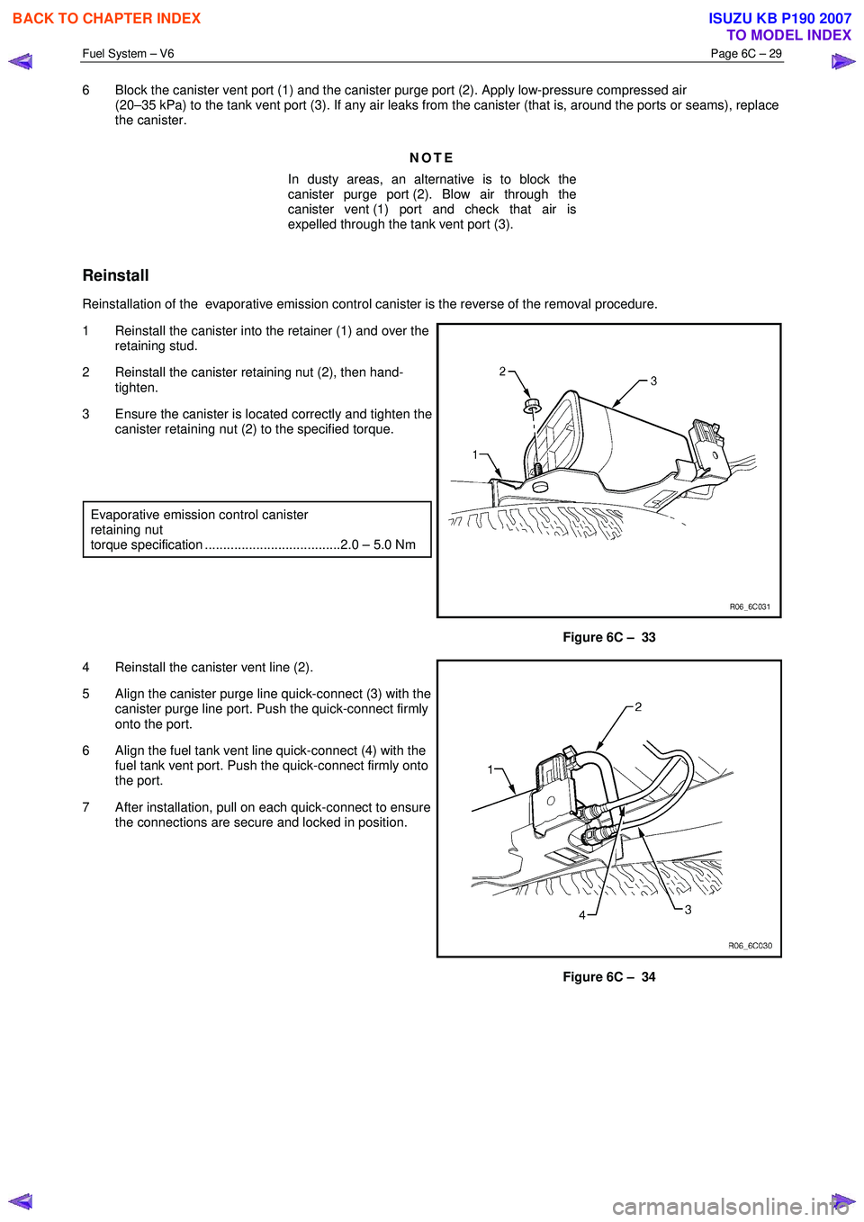
1 Reinstall the canister into the retainer (1) and over the retaining stud.
2 Reinstall the canister retaining nut (2), then hand- tighten.
3 Ensure the canister is located correctly and tighten the canister retaining nut (2) to the specified torque.
Evaporative emission control canister
retaining nut
torque specification .....................................2.0 – 5.0 Nm
Figure 6C – 33
4 Reinstall the canister vent line (2).
5 Align the canister purge line quick-connect (3) with the canister purge line port. Push the quick-connect firmly
onto the port.
6 Align the fuel tank vent line quick-connect (4) with the fuel tank vent port. Push the quick-connect firmly onto
the port.
7 After installation, pull on each quick-connect to ensure the connections are secure and locked in position.
Figure 6C – 34
BACK TO CHAPTER INDEX
TO MODEL INDEX
ISUZU KB P190 2007
Page 3232 of 6020
Fuel System – V6 Page 6C – 30
4.7 Fuel Tank Siphon Procedure
• Fuel vapour remains in the modular fuel
pump and sender assembly and fuel lines
that can be spilled during service
operations. Ensure no naked flames or
other ignition sources are nearby. Ensure
all cellular phones (and transmission
devices that may cause any metal objects
to become unintentional receiving
antennas) are switched off.
• Place a dry chemical (Class B) fire
extinguisher nearby before performing any
on-vehicle service procedures. Failure to
follow these precautions may result in
personal injury.
For an exploded view of fuel tank components, refer Figure 6C – 17.
1 Depressurise the fuel system, refer to 3.4 Fuel System Depressurisation.
2 Reinstall the fuel pump relay, refer to 8A Electrical Body and Chassis.
Disconnecting the battery affects certain
vehicle electronic systems. 1.1 WARNING,
CAUTION and NOTES.
3 Disconnect the negative battery terminal.
4 Remove the fuel filler cap.
NOTE
Lubricate the fuel siphon hose with J36850
TransJel Transmission Assembly Lubricant or
equivalent to aid hose insertion. Use only an
approved lubricant.
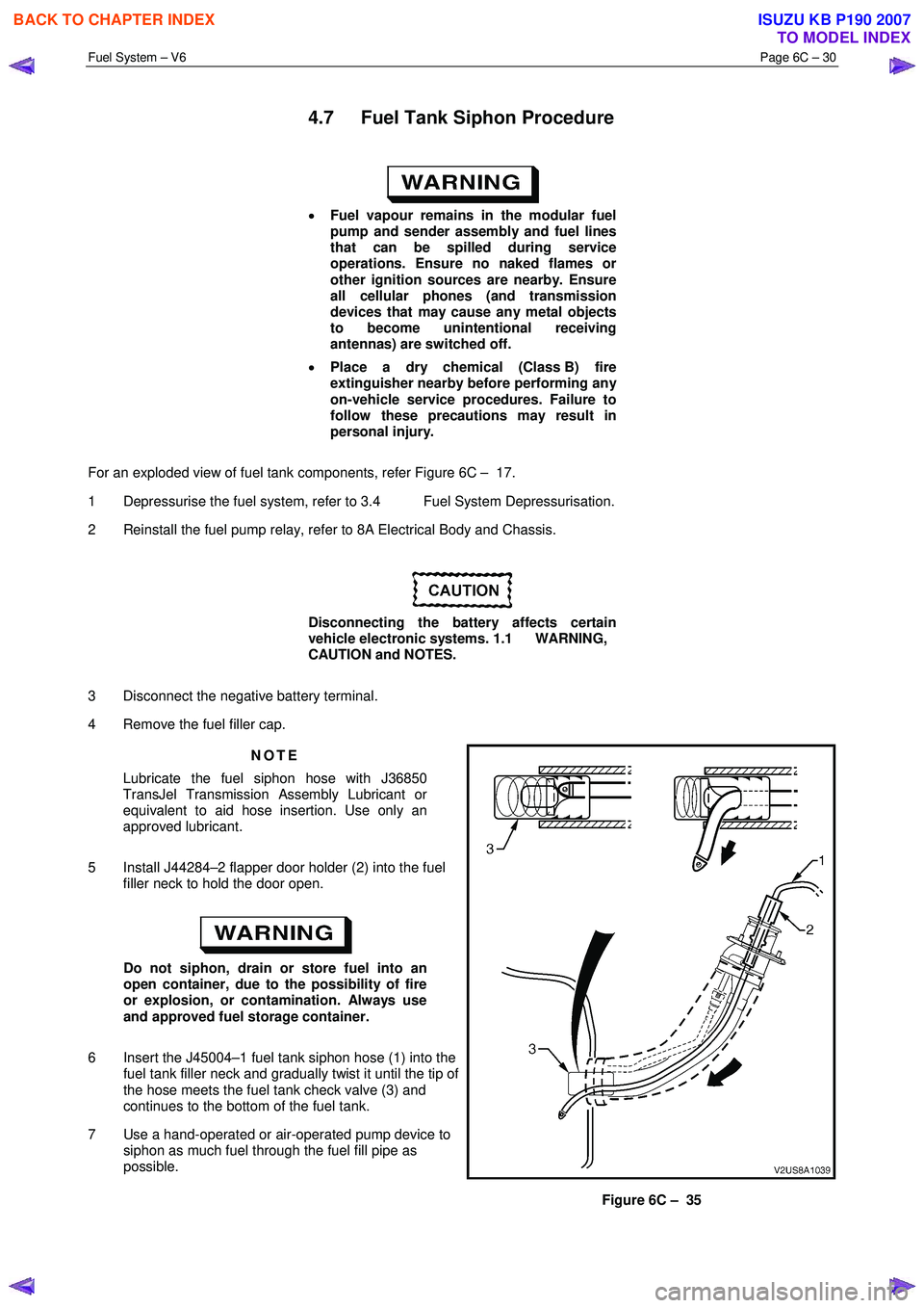
5 Install J44284–2 flapper door holder (2) into the fuel filler neck to hold the door open.
Do not siphon, drain or store fuel into an
open container, due to the possibility of fire
or explosion, or contamination. Always use
and approved fuel storage container.
6 Insert the J45004–1 fuel tank siphon hose (1) into the fuel tank filler neck and gradually twist it until the tip of
the hose meets the fuel tank check valve (3) and
continues to the bottom of the fuel tank.
7 Use a hand-operated or air-operated pump device to siphon as much fuel through the fuel fill pipe as
possible.
Figure 6C – 35
BACK TO CHAPTER INDEX
TO MODEL INDEX
ISUZU KB P190 2007
Page 3234 of 6020
Fuel System – V6 Page 6C – 32
4.8 Fuel Filler Cap
The fuel filler cap is a 'screw on' type, with an integrated tightening torque limiting mechanism. W hen installing the fuel
filler cap, tighten it until a ratcheting (clicking) sound is audible, indicating the fuel filler cap is properly tightened. Th e fuel
filler cap is tethered to the fuel filler pocket.
Remove
The fuel filler cap requires a quarter of a turn anticlockwise to be removed.
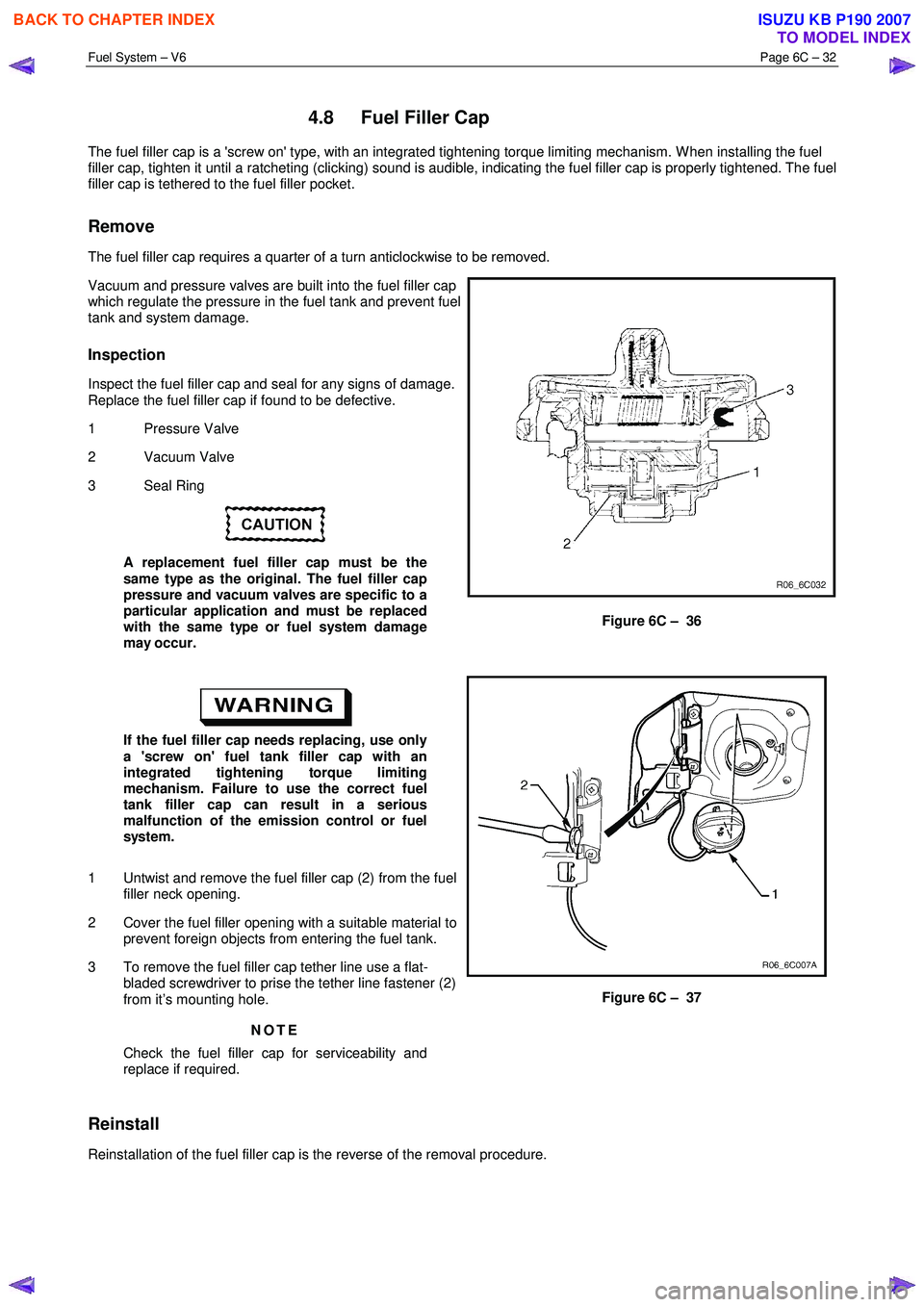
Vacuum and pressure valves are built into the fuel filler cap
which regulate the pressure in the fuel tank and prevent fuel
tank and system damage.
Inspection
Inspect the fuel filler cap and seal for any signs of damage.
Replace the fuel filler cap if found to be defective.
1 Pressure Valve
2 Vacuum Valve
3 Seal Ring
A replacement fuel filler cap must be the
same type as the original. The fuel filler cap
pressure and vacuum valves are specific to a
particular application and must be replaced
with the same type or fuel system damage
may occur.
Figure 6C – 36
If the fuel filler cap needs replacing, use only
a 'screw on' fuel tank filler cap with an
integrated tightening torque limiting
mechanism. Failure to use the correct fuel
tank filler cap can result in a serious
malfunction of the emission control or fuel
system.
1 Untwist and remove the fuel filler cap (2) from the fuel filler neck opening.
2 Cover the fuel filler opening with a suitable material to prevent foreign objects from entering the fuel tank.
3 To remove the fuel filler cap tether line use a flat- bladed screwdriver to prise the tether line fastener (2)
from it’s mounting hole.
NOTE
Check the fuel filler cap for serviceability and
replace if required.
Figure 6C – 37
Reinstall
Reinstallation of the fuel filler cap is the reverse of the removal procedure.
BACK TO CHAPTER INDEX
TO MODEL INDEX
ISUZU KB P190 2007
Page 3235 of 6020
Fuel System – V6 Page 6C – 33
4.9 Fuel Lines
Remove
• A depressurised fuel system contains fuel
in the fuel filter and fuel lines that can be
spilled during service operations.
• Fuel vapour remains in the fuel tank even
when completely empty. Seal all openings
in the fuel tank using suitable material or a
plastic plug. Ensure no naked flames or
other ignition sources are nearby. Ensure
all cellular phones (and transmission
devices that may cause any metal objects
to become unintentional receiving
antennas) are switched off.
• Place a dry chemical (Class B) fire
extinguisher nearby before performing any
on-vehicle service procedures. Failure to
follow these precautions may result in
personal injury.
• Wear safety glasses when using
compressed air. Do not blow compressed
air onto any body part.
1 Remove the fuel pump relay, refer to 8A Electrical Body and Chassis.
2 Depressurise the fuel system, refer to 3.4 Fuel System Depressurisation.
Never drain or store fuel into an open
container, due to the possibility of fire or
explosion.
3 Raise the vehicle, preferably on a hoist, refer to 0A General Information.
Before proceeding, clean all traces of dirt and
other foreign material from the fuel lines.
4 Use compressed air to ensure that all dirt and foreign materials are removed from all fuel connections before the parts are disconnected.
5 If required, remove the stone guard, refer to Figure 6C – 17 and fuel lines. Use the following illustrations showing the fuel line layout and location of other items relating to the fuel system as a guide, also refer to 4.1 Fuel Lines
And Quick Connect Fittings and 4.6 Evaporative Emission Control Canister.
BACK TO CHAPTER INDEX
TO MODEL INDEX
ISUZU KB P190 2007
Page 3236 of 6020
Fuel System – V6 Page 6C – 34
Fuel Tank Lines
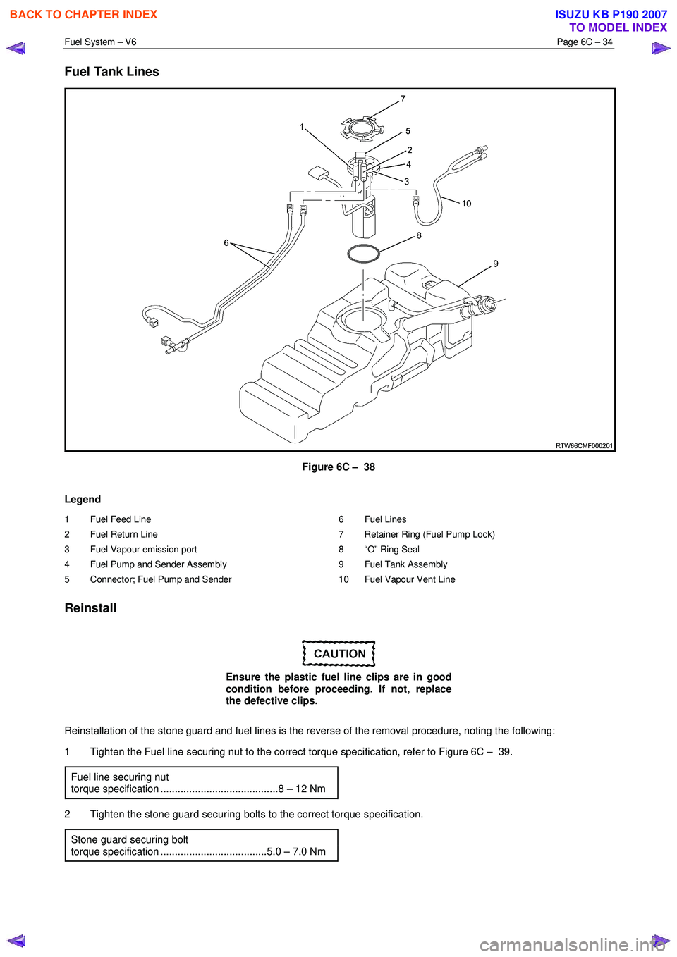
Figure 6C – 38
Legend
1 Fuel Feed Line
2 Fuel Return Line
3 Fuel Vapour emission port
4 Fuel Pump and Sender Assembly
5 Connector; Fuel Pump and Sender 6 Fuel Lines
7 Retainer Ring (Fuel Pump Lock)
8 “O” Ring Seal
9 Fuel Tank Assembly
10 Fuel Vapour Vent Line
Reinstall
Ensure the plastic fuel line clips are in good
condition before proceeding. If not, replace
the defective clips.
Reinstallation of the stone guard and fuel lines is the reverse of the removal procedure, noting the following:
1 Tighten the Fuel line securing nut to the correct torque specification, refer to Figure 6C – 39.
Fuel line securing nut
torque specification .........................................8 – 12 Nm
2 Tighten the stone guard securing bolts to the correct torque specification. Stone guard securing bolt
torque specification .....................................5.0 – 7.0 Nm
BACK TO CHAPTER INDEX
TO MODEL INDEX
ISUZU KB P190 2007
Page 3237 of 6020
Fuel System – V6 Page 6C – 35
Fuel Line Routing
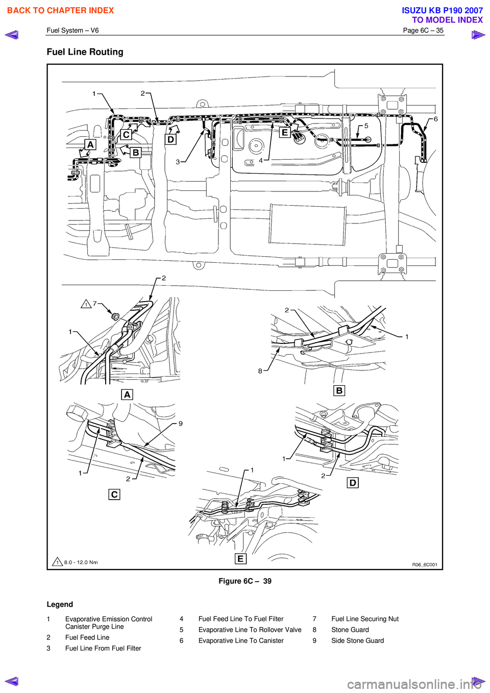
Figure 6C – 39
Legend
1 Evaporative Emission Control Canister Purge Line
2 Fuel Feed Line
3 Fuel Line From Fuel Filter 4 Fuel Feed Line To Fuel Filter
5 Evaporative Line To Rollover Valve
6 Evaporative Line To Canister
7 Fuel Line Securing Nut
8 Stone Guard
9 Side Stone Guard
BACK TO CHAPTER INDEX
TO MODEL INDEX
ISUZU KB P190 2007
Page 3238 of 6020
Fuel System – V6 Page 6C – 36
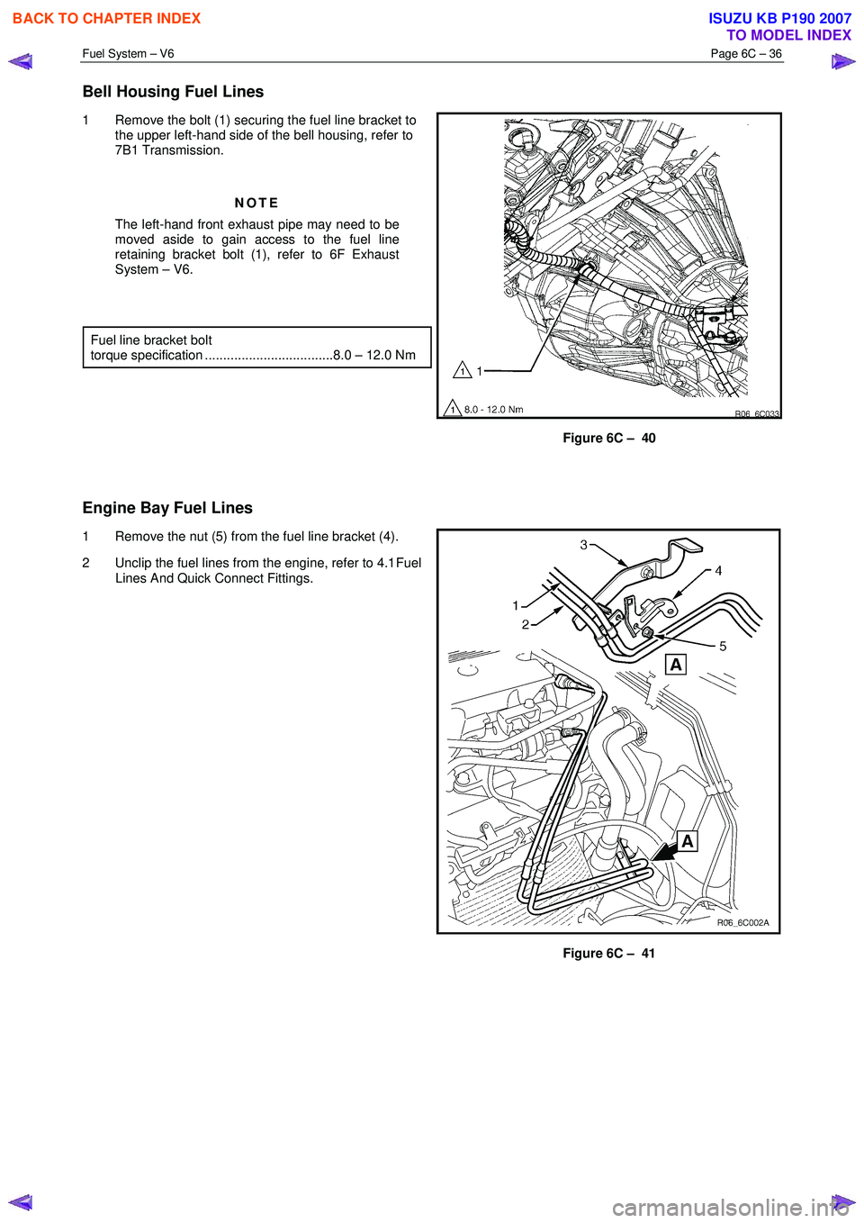
Bell Housing Fuel Lines
1 Remove the bolt (1) securing the fuel line bracket to
the upper left-hand side of the bell housing, refer to
7B1 Transmission.
NOTE
The left-hand front exhaust pipe may need to be
moved aside to gain access to the fuel line
retaining bracket bolt (1), refer to 6F Exhaust
System – V6.
Fuel line bracket bolt
torque specification ...................................8.0 – 12.0 Nm
Figure 6C – 40
Engine Bay Fuel Lines
1 Remove the nut (5) from the fuel line bracket (4).
2 Unclip the fuel lines from the engine, refer to 4.1 Fuel
Lines And Quick Connect Fittings.
Figure 6C – 41
BACK TO CHAPTER INDEX
TO MODEL INDEX
ISUZU KB P190 2007
Page 3239 of 6020
Fuel System – V6 Page 6C – 37
4.10 Rollover Valve
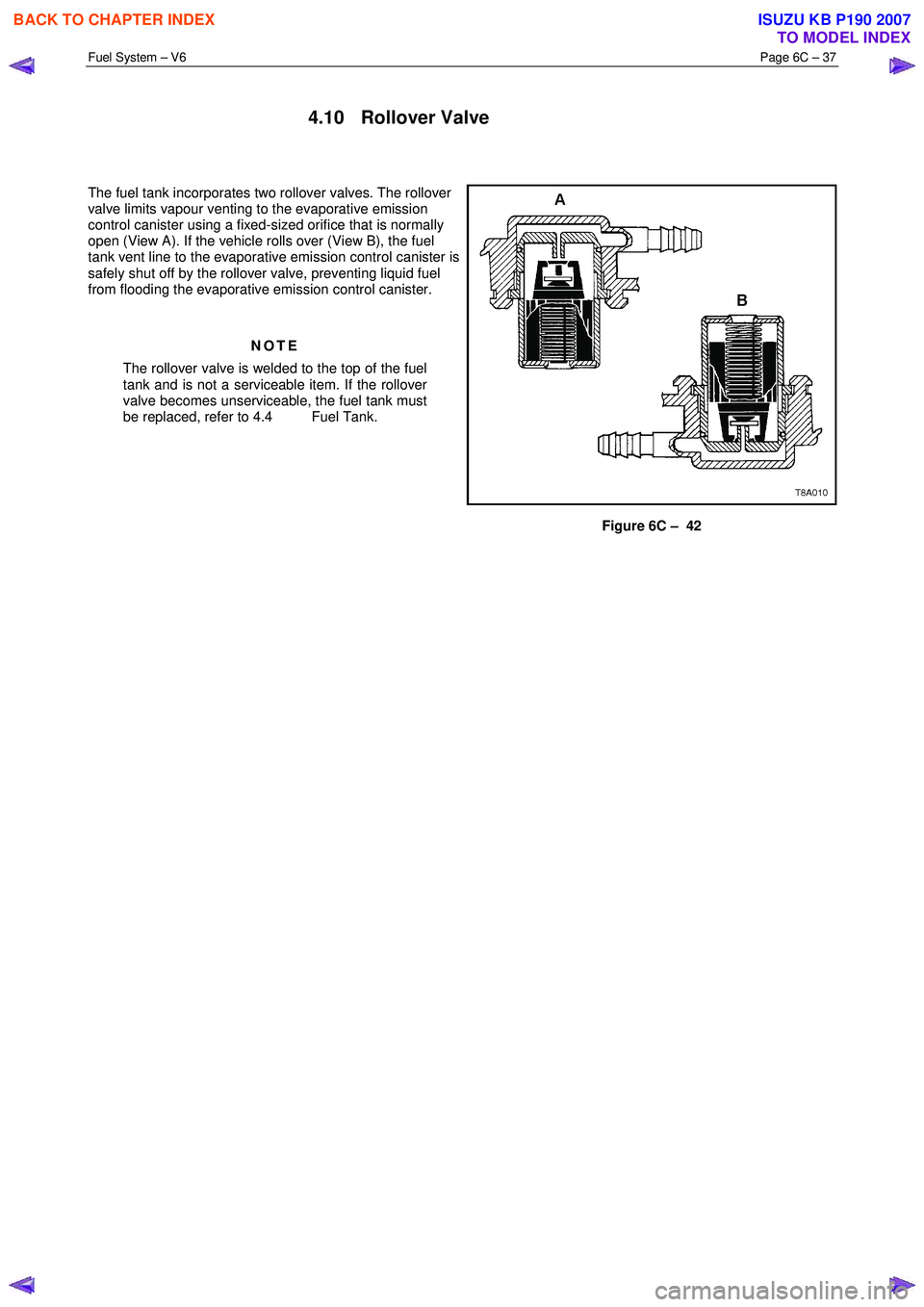
The fuel tank incorporates two rollover valves. The rollover
valve limits vapour venting to the evaporative emission
control canister using a fixed-sized orifice that is normally
open (View A). If the vehicle rolls over (View B), the fuel
tank vent line to the evaporative emission control canister is
safely shut off by the rollover valve, preventing liquid fuel
from flooding the evaporative emission control canister.
NOTE
The rollover valve is welded to the top of the fuel
tank and is not a serviceable item. If the rollover
valve becomes unserviceable, the fuel tank must
be replaced, refer to 4.4 Fuel Tank.
Figure 6C – 42
BACK TO CHAPTER INDEX
TO MODEL INDEX
ISUZU KB P190 2007