Fuel line ISUZU KB P190 2007 Workshop User Guide
[x] Cancel search | Manufacturer: ISUZU, Model Year: 2007, Model line: KB P190, Model: ISUZU KB P190 2007Pages: 6020, PDF Size: 70.23 MB
Page 811 of 6020
6A – 6 ENGINE MECHANICAL
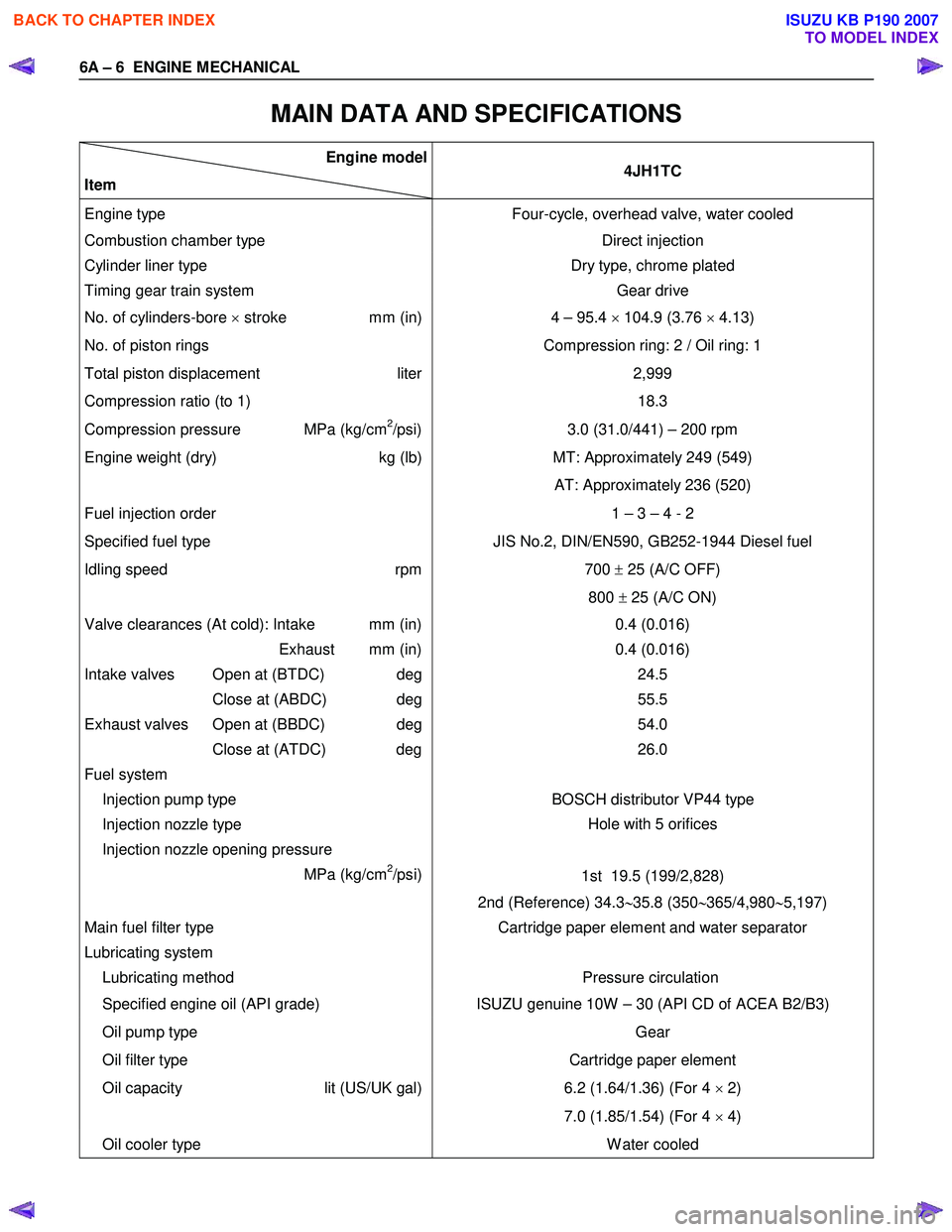
MAIN DATA AND SPECIFICATIONS
Engine model
Item 4JH1TC
Engine type
Four-cycle, overhead valve, water cooled
Combustion chamber type Direct injection
Cylinder liner type
Timing gear train system Dry type, chrome plated
Gear drive
No. of cylinders-bore × stroke mm (in) 4 – 95.4 × 104.9 (3.76 × 4.13)
No. of piston rings Compression ring: 2 / Oil ring: 1
Total piston displacement liter
Compression ratio (to 1) 2,999
18.3
Compression pressure MPa (kg/cm2/psi) 3.0 (31.0/441) – 200 rpm
Engine weight (dry) kg (lb)MT: Approximately 249 (549)
AT: Approximately 236 (520)
Fuel injection order 1 – 3 – 4 - 2
Specified fuel type JIS No.2, DIN/EN590, GB252-1944 Diesel fuel
Idling speed rpm
700 ± 25 (A/C OFF)
800 ± 25 (A/C ON)
Valve clearances (At cold): Intake mm (in)
Exhaust mm (in)
Intake valves Open at (BTDC) deg
Close at (ABDC) deg
Exhaust valves Open at (BBDC) deg
Close at (ATDC) deg
Fuel system
Injection pump type 0.4 (0.016)
0.4 (0.016) 24.5
55.5
54.0
26.0
BOSCH distributor VP44 type
Injection nozzle type
Injection nozzle opening pressure
MPa (kg/cm
2/psi) Hole with 5 orifices
1st 19.5 (199/2,828)
2nd (Reference) 34.3 ∼35.8 (350 ∼365/4,980 ∼5,197)
Main fuel filter type
Lubricating system
Lubricating method Cartridge paper element and water separator
Pressure circulation
Specified engine oil (API grade) ISUZU genuine 10W – 30 (API CD of ACEA B2/B3)
Oil pump type
Oil filter type Gear
Cartridge paper element
Oil capacity lit (US/UK gal)
6.2 (1.64/1.36) (For 4
× 2)
7.0 (1.85/1.54) (For 4 × 4)
Oil cooler type W ater cooled
BACK TO CHAPTER INDEX
TO MODEL INDEX
ISUZU KB P190 2007
Page 841 of 6020
6A – 36 ENGINE MECHANICAL
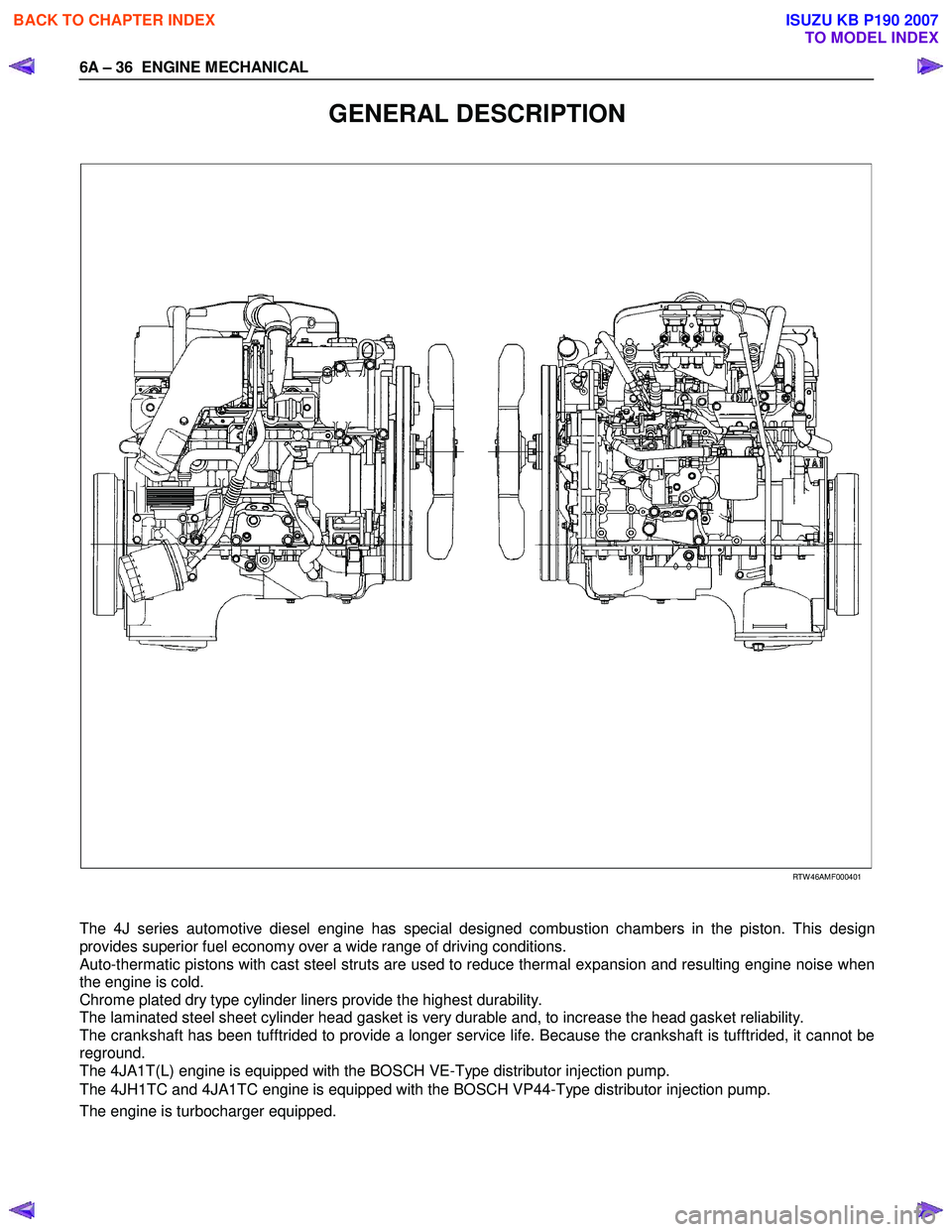
GENERAL DESCRIPTION
RTW 46AMF000401
The 4J series automotive diesel engine has special designed combustion chambers in the piston. This design
provides superior fuel economy over a wide range of driving conditions.
Auto-thermatic pistons with cast steel struts are used to reduce thermal expansion and resulting engine noise when
the engine is cold.
Chrome plated dry type cylinder liners provide the highest durability.
The laminated steel sheet cylinder head gasket is very durable and, to increase the head gasket reliability.
The crankshaft has been tufftrided to provide a longer service life. Because the crankshaft is tufftrided, it cannot be
reground.
The 4JA1T(L) engine is equipped with the BOSCH VE-Type distributor injection pump.
The 4JH1TC and 4JA1TC engine is equipped with the BOSCH VP44-Type distributor injection pump.
The engine is turbocharger equipped.
BACK TO CHAPTER INDEX
TO MODEL INDEX
ISUZU KB P190 2007
Page 966 of 6020

6C – 2 FUEL SYSTEM
MAIN DATA AND SPECIFICATIONS
Description Item
4JA1T (L) 4JA1TC 4JH1TC
Injection pump type Bosch distributor
VE type Bosch distributor VP44 type
Governor type
Mechanical variable
(Half speed oil pressure) Electrical controled
Timer type
Oil pressure Electrical controled
Fuel feed pump type Vane with input shaft
Injection nozzle type Hole type
Number of injection nozzle orifices 5
Injection nozzle orifices
Inside diameter mm (in) 0.19 (0.0075) 0.17 (0.0067) 0.21 (0.0083)
19.1 (195) 19.0 (194) 19.5 (199) Injection nozzle designed operating
pressure MPa (kg/cm2) 1st
2nd 25.0 (255)
33.5 (328) 33.8 (331)
Main fuel filter type Disposable cartridge paper element
Precautions
When working on the fuel system, there are several things
to keep in mind:
•
Any time the fuel system is being worked on,
disconnect the negative battery cable except fo
r
those tests where battery voltage is required.
•
Always keep a dry chemical (Class B) fire
extinguisher near the work area.
• Replace all pipes with the same pipe and fittings that
were removed.
• Clean and inspect “O” rings. Replace if required.
•
Always relieve the line pressure before servicing any
fuel system components.
• Do not attempt repairs on the fuel system until you
have read the instructions and checked the pictures
relating to that repair.
• Adhere to all Notices and Cautions.
NOTE:
Injection nozzle adjustment is possible only on the 4JA1L
engine.
BACK TO CHAPTER INDEX
TO MODEL INDEX
ISUZU KB P190 2007
Page 973 of 6020
FUEL SYSTEM 6C – 9
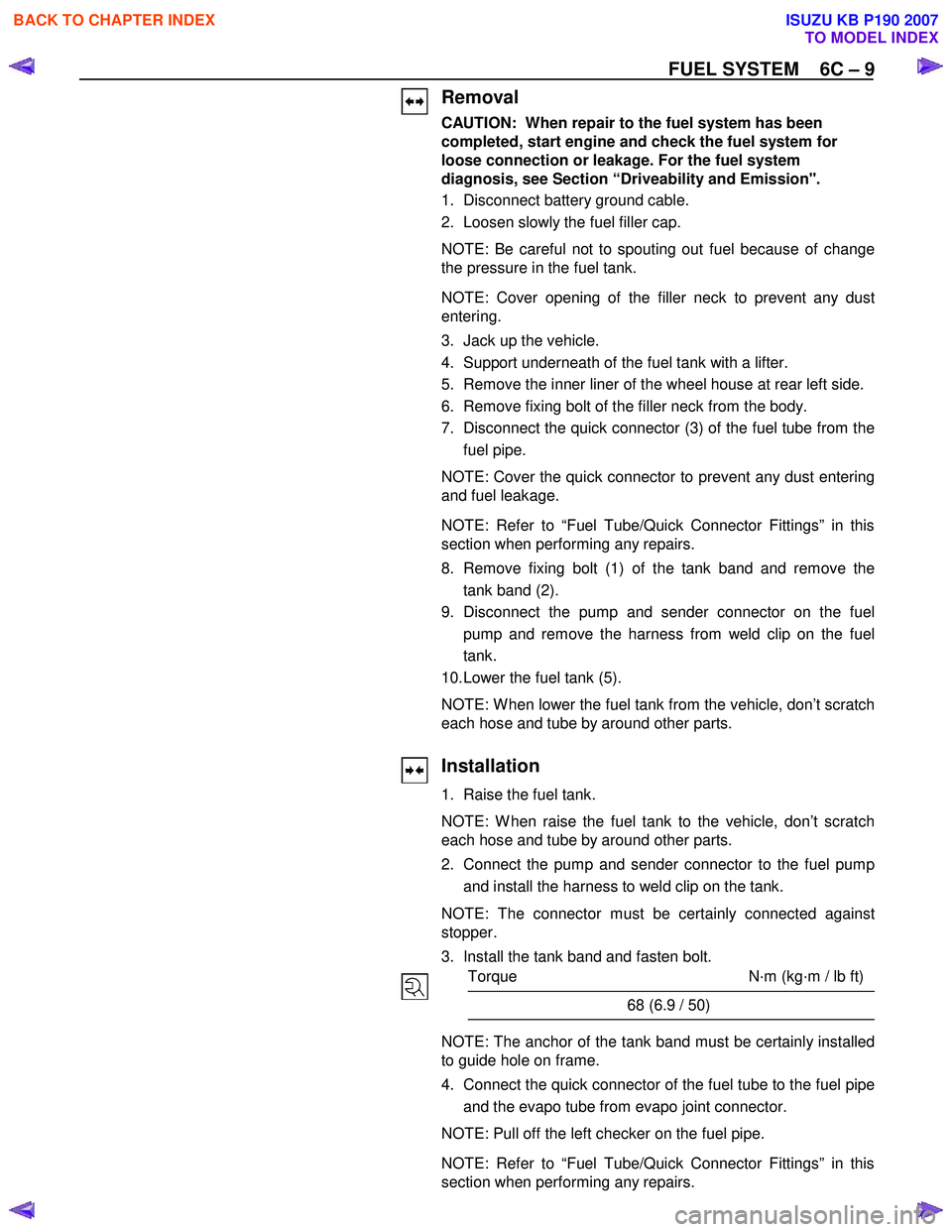
Removal
CAUTION: When repair to the fuel system has been
completed, start engine and check the fuel system for
loose connection or leakage. For the fuel system
diagnosis, see Section “Driveability and Emission".
1. Disconnect battery ground cable.
2. Loosen slowly the fuel filler cap.
NOTE: Be careful not to spouting out fuel because of change
the pressure in the fuel tank.
NOTE: Cover opening of the filler neck to prevent any dust
entering.
3. Jack up the vehicle.
4. Support underneath of the fuel tank with a lifter.
5. Remove the inner liner of the wheel house at rear left side.
6. Remove fixing bolt of the filler neck from the body.
7. Disconnect the quick connector (3) of the fuel tube from the
fuel pipe.
NOTE: Cover the quick connector to prevent any dust entering
and fuel leakage.
NOTE: Refer to “Fuel Tube/Quick Connector Fittings” in this
section when performing any repairs.
8. Remove fixing bolt (1) of the tank band and remove the tank band (2).
9. Disconnect the pump and sender connector on the fuel
pump and remove the harness from weld clip on the fuel
tank.
10. Lower the fuel tank (5).
NOTE: W hen lower the fuel tank from the vehicle, don’t scratch
each hose and tube by around other parts.
Installation
1. Raise the fuel tank.
NOTE: W hen raise the fuel tank to the vehicle, don’t scratch
each hose and tube by around other parts.
2. Connect the pump and sender connector to the fuel pump and install the harness to weld clip on the tank.
NOTE: The connector must be certainly connected against
stopper.
3. Install the tank band and fasten bolt.
Torque N·m (kg·m / lb ft)
68 (6.9 / 50)
NOTE: The anchor of the tank band must be certainly installed
to guide hole on frame.
4. Connect the quick connector of the fuel tube to the fuel pipe and the evapo tube from evapo joint connector.
NOTE: Pull off the left checker on the fuel pipe.
NOTE: Refer to “Fuel Tube/Quick Connector Fittings” in this
section when performing any repairs.
BACK TO CHAPTER INDEX
TO MODEL INDEX
ISUZU KB P190 2007
Page 974 of 6020
6C – 10 FUEL SYSTEM
5. Install the filler neck to the body with bolt.
6. Install the inner liner of the wheel house at rear left side.
7. Remove lifter from the fuel tank.
8. Lower the vehicle.
9. Tigten the filler cap until at least three clicks.
10. Connect the battery ground cable.
BACK TO CHAPTER INDEX
TO MODEL INDEX
ISUZU KB P190 2007
Page 984 of 6020
6C – 20 FUEL SYSTEM
020L200017
RTW 46CSH000201
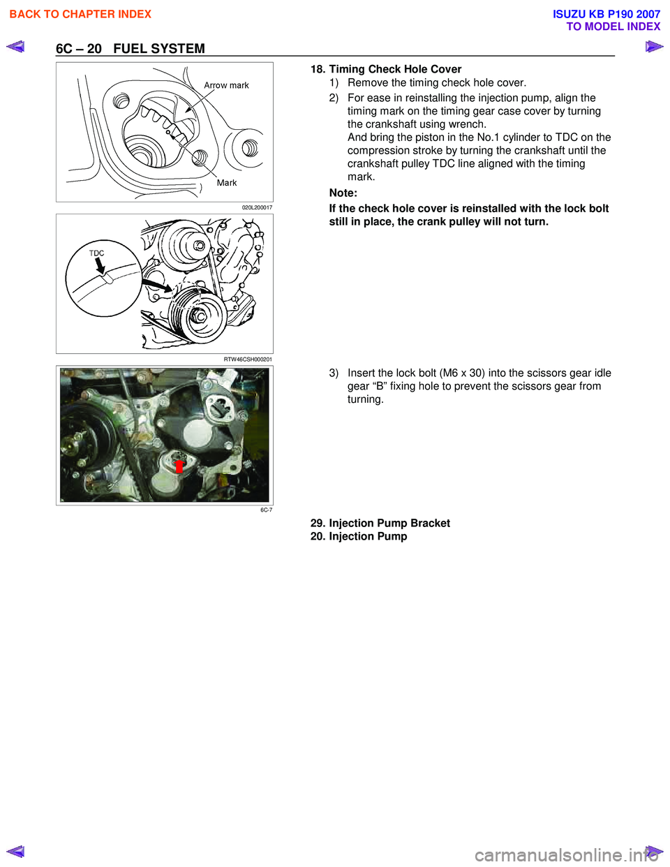
18. Timing Check Hole Cover
1) Remove the timing check hole cover.
2) For ease in reinstalling the injection pump, align the timing mark on the timing gear case cover by turning
the crankshaft using wrench.
And bring the piston in the No.1 cylinder to TDC on the
compression stroke by turning the crankshaft until the
crankshaft pulley TDC line aligned with the timing
mark.
Note:
If the check hole cover is reinstalled with the lock bolt
still in place, the crank pulley will not turn.
6C-7
3) Insert the lock bolt (M6 x 30) into the scissors gear idle
gear “B” fixing hole to prevent the scissors gear from
turning.
29. Injection Pump Bracket
20. Injection Pump
BACK TO CHAPTER INDEX
TO MODEL INDEX
ISUZU KB P190 2007
Page 985 of 6020
FUEL SYSTEM 6C – 21
RTW 46CSH000201
Installation
1. Injection Pump
1) Install the injection pump gear (W hen gear is removed).
Injection Pump Gear Nut N⋅m (kg ⋅m/lb ft)
64 (6.5 / 47)
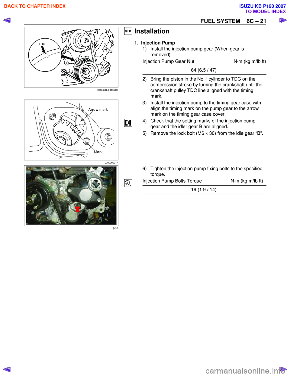
2) Bring the piston in the No.1 cylinder to TDC on the
compression stroke by turning the crankshaft until the
crankshaft pulley TDC line aligned with the timing
mark.
020L200017
3) Install the injection pump to the timing gear case with
align the timing mark on the pump gear to the arrow
mark on the timing gear case cover.
4) Check that the setting marks of the injection pump gear and the idler gear B are aligned.
5) Remove the lock bolt (M6 × 30) from the idle gear “B”.
6C-7
6) Tighten the injection pump fixing bolts to the specified
torque.
Injection Pump Bolts Torque N·m (kg·m/lb ft)
19 (1.9 / 14)
BACK TO CHAPTER INDEX
TO MODEL INDEX
ISUZU KB P190 2007
Page 996 of 6020
6C – 32 FUEL SYSTEM
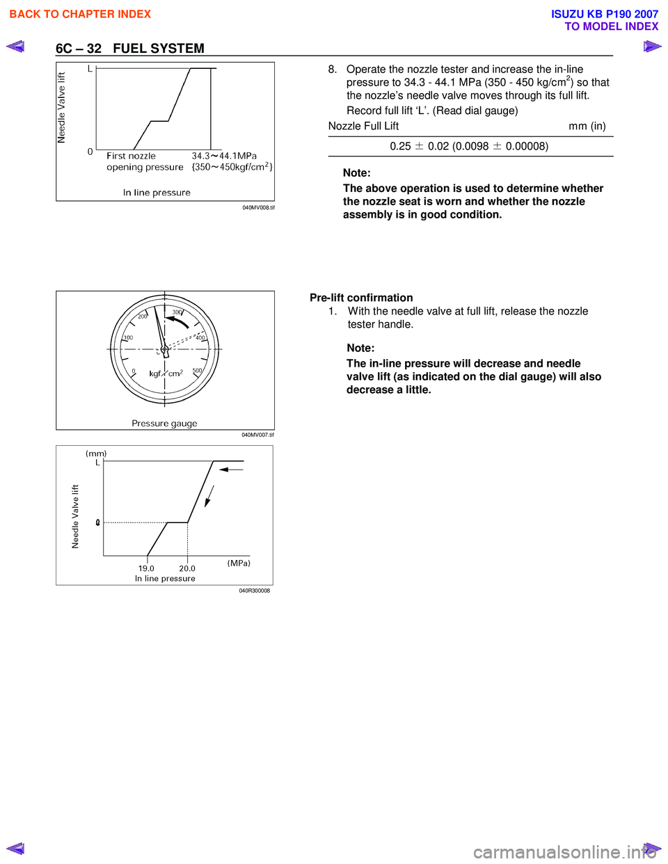
8. Operate the nozzle tester and increase the in-line
pressure to 34.3 - 44.1 MPa (350 - 450 kg/cm2) so that
the nozzle’s needle valve moves through its full lift.
Record full lift ‘L’. (Read dial gauge)
Nozzle Full Lift mm (in)
0.25 ± 0.02 (0.0098 ± 0.00008)
Note:
The above operation is used to determine whether
the nozzle seat is worn and whether the nozzle
assembly is in good condition.
Pre-lift confirmation 1. W ith the needle valve at full lift, release the nozzle tester handle.
Note:
The in-line pressure will decrease and needle
valve lift (as indicated on the dial gauge) will also
decrease a little.
040R300008
040MV007.tif040MV008.tif
BACK TO CHAPTER INDEX
TO MODEL INDEX
ISUZU KB P190 2007
Page 997 of 6020
FUEL SYSTEM 6C – 33
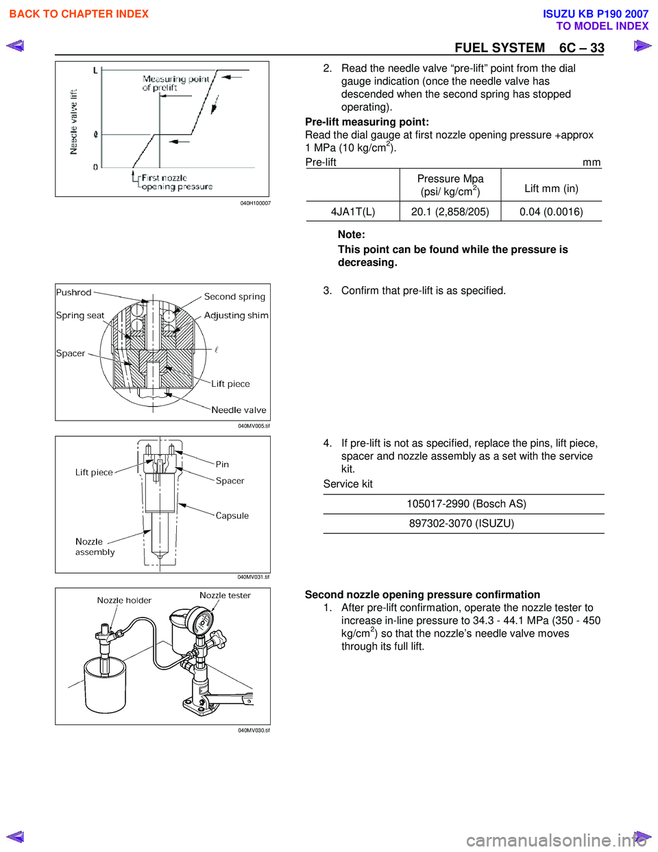
2. Read the needle valve “pre-lift” point from the dial gauge indication (once the needle valve has
descended when the second spring has stopped
operating).
Pre-lift measuring point:
Read the dial gauge at first nozzle opening pressure +approx
1 MPa (10 kg/cm
2).
Pre-lift mm
Pressure Mpa
(psi/ kg/cm
2) Lift mm (in)
4JA1T(L) 20.1 (2,858/205) 0.04 (0.0016)
Note:
This point can be found while the pressure is
decreasing.
3. Confirm that pre-lift is as specified.
4. If pre-lift is not as specified, replace the pins, lift piece, spacer and nozzle assembly as a set with the service
kit.
Service kit
105017-2990 (Bosch AS)
897302-3070 (ISUZU)
Second nozzle opening pressure confirmation
1. After pre-lift confirmation, operate the nozzle tester to increase in-line pressure to 34.3 - 44.1 MPa (350 - 450
kg/cm
2) so that the nozzle’s needle valve moves
through its full lift.
040MV005.tif
040MV031.tif
040MV030.tif 040H100007
BACK TO CHAPTER INDEX
TO MODEL INDEX
ISUZU KB P190 2007
Page 998 of 6020
6C – 34 FUEL SYSTEM
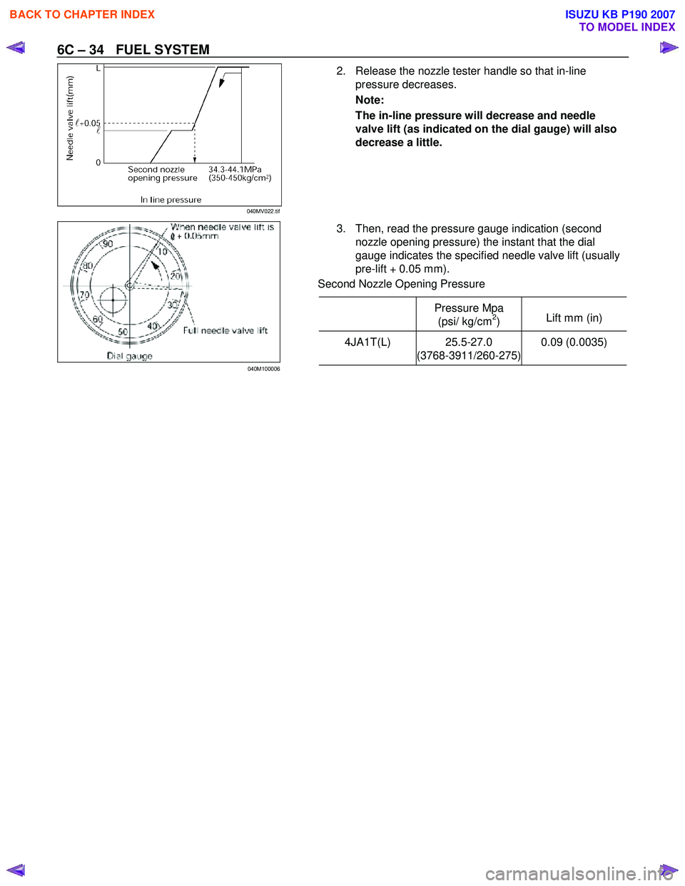
2. Release the nozzle tester handle so that in-line
pressure decreases.
Note:
The in-line pressure will decrease and needle
valve lift (as indicated on the dial gauge) will also
decrease a little.
3. Then, read the pressure gauge indication (second
nozzle opening pressure) the instant that the dial
gauge indicates the specified needle valve lift (usually
pre-lift + 0.05 mm).
Second Nozzle Opening Pressure
Pressure Mpa
(psi/ kg/cm
2) Lift mm (in)
4JA1T(L) 25.5-27.0
(3768-3911/260-275) 0.09 (0.0035)
040MV022.tif
040M100006
BACK TO CHAPTER INDEX
TO MODEL INDEX
ISUZU KB P190 2007