wheel size ISUZU KB P190 2007 Workshop Repair Manual
[x] Cancel search | Manufacturer: ISUZU, Model Year: 2007, Model line: KB P190, Model: ISUZU KB P190 2007Pages: 6020, PDF Size: 70.23 MB
Page 406 of 6020
3E-2 WHEELS AND TIRES
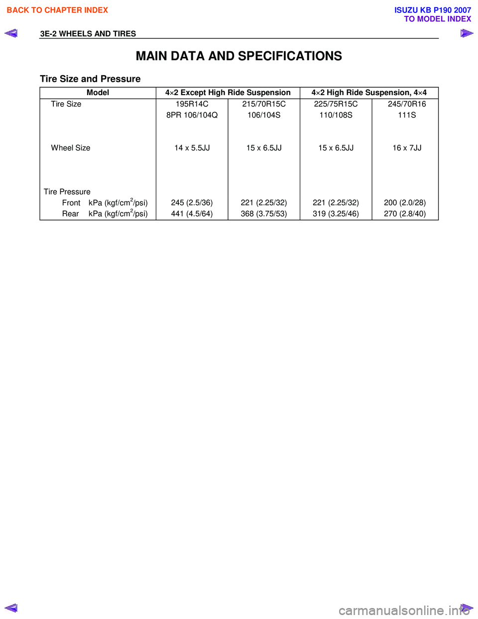
MAIN DATA AND SPECIFICATIONS
Tire Size and Pressure
Model 4×
××
×
2 Except High Ride Suspension 4×
××
×
2 High Ride Suspension, 4 ×
××
×
4
Tire Size
W heel Size
195R14C
8PR 106/104Q
14 x 5.5JJ
215/70R15C
106/104S
15 x 6.5JJ
225/75R15C
110/108S
15 x 6.5JJ
245/70R16
111S
16 x 7JJ
Tire Pressure
Front kPa (kgf/cm2/psi)
Rear kPa (kgf/cm2/psi) 245 (2.5/36)
441 (4.5/64) 221 (2.25/32)
368 (3.75/53) 221 (2.25/32)
319 (3.25/46) 200 (2.0/28)
270 (2.8/40)
BACK TO CHAPTER INDEX
TO MODEL INDEX
ISUZU KB P190 2007
Page 409 of 6020
WHEELS AND TIRES 3E-5
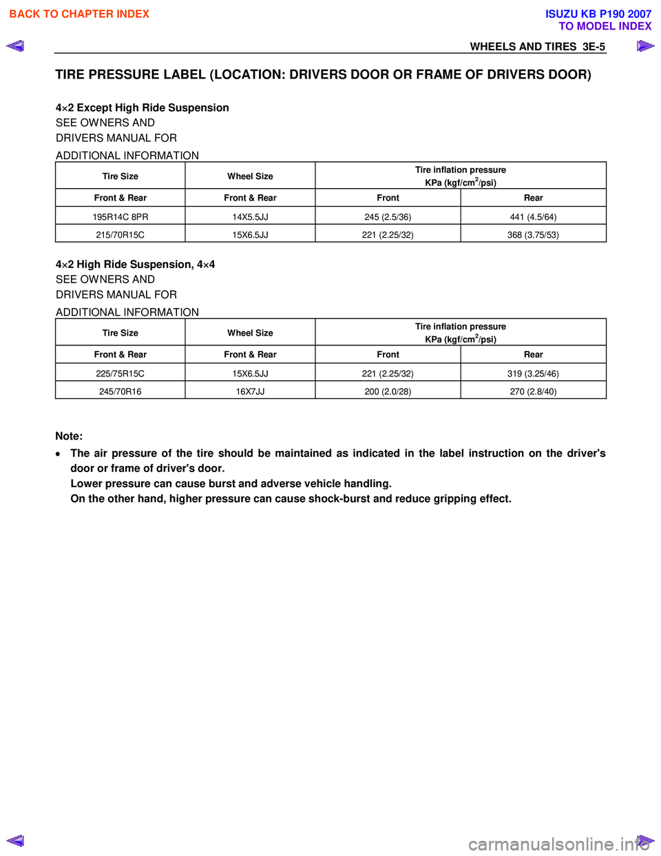
TIRE PRESSURE LABEL (LOCATION: DRIVERS DOOR OR FRAME OF DRIVERS DOOR)
4 ×
××
×
2 Except High Ride Suspension
SEE OW NERS AND
DRIVERS MANUAL FOR
ADDITIONAL INFORMATION
Tire Size Wheel Size Tire inflation pressure
KPa (kgf/cm
2/psi)
Front & Rear Front & Rear Front Rear
195R14C 8PR 14X5.5JJ 245 (2.5/36) 441 (4.5/64)
215/70R15C 15X6.5JJ 221 (2.25/32) 368 (3.75/53)
4 ×
××
×
2 High Ride Suspension, 4 ×
××
×
4
SEE OW NERS AND
DRIVERS MANUAL FOR
ADDITIONAL INFORMATION
Tire Size Wheel Size Tire inflation pressure
KPa (kgf/cm
2/psi)
Front & Rear Front & Rear Front Rear
225/75R15C 15X6.5JJ 221 (2.25/32) 319 (3.25/46)
245/70R16 16X7JJ 200 (2.0/28) 270 (2.8/40)
Note:
•
••
•
The air pressure of the tire should be maintained as indicated in the label instruction on the driver's
door or frame of driver's door.
Lower pressure can cause burst and adverse vehicle handling.
On the other hand, higher pressure can cause shock-burst and reduce gripping effect.
BACK TO CHAPTER INDEX
TO MODEL INDEX
ISUZU KB P190 2007
Page 507 of 6020
FRONT WHEEL DRIVE 4C1-3
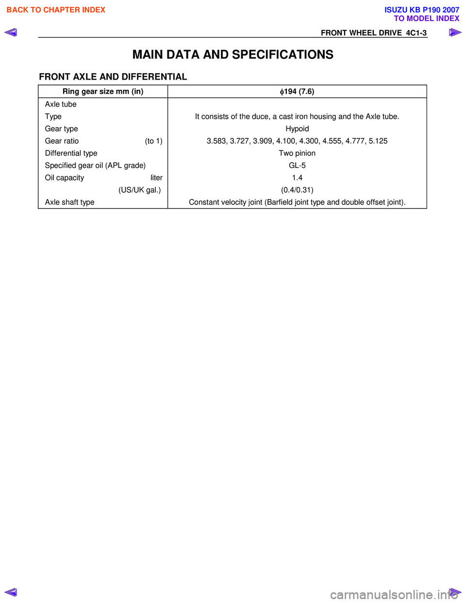
MAIN DATA AND SPECIFICATIONS
FRONT AXLE AND DIFFERENTIAL
Ring gear size mm (in) φ
φφ
φ
194 (7.6)
Axle tube
Type It consists of the duce, a cast iron housing and the Axle tube.
Gear type Hypoid
Gear ratio (to 1) 3.583, 3.727, 3.909, 4.100, 4.300, 4.555, 4.777, 5.125
Differential type Two pinion
Specified gear oil (APL grade) GL-5
Oil capacity liter 1.4
(US/UK gal.) (0.4/0.31)
Axle shaft type Constant velocity joint (Barfield joint type and double offset joint).
BACK TO CHAPTER INDEX
TO MODEL INDEX
ISUZU KB P190 2007
Page 657 of 6020
5A-64 BRAKE CONTROL SYSTEM
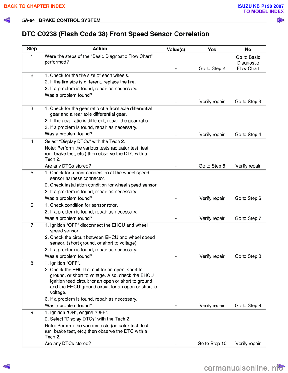
DTC C0238 (Flash Code 38) Front Speed Sensor Correlation
Step Action Value(s) Yes No
1 W ere the steps of the “Basic Diagnostic Flow Chart”
performed?
- Go to Step 2 Go to Basic
Diagnostic
Flow Chart
2 1. Check for the tire size of each wheels.
2. If the tire size is different, replace the tire.
3. If a problem is found, repair as necessary. W as a problem found? - Verify repair Go to Step 3
3 1. Check for the gear ratio of a front axle differential gear and a rear axle differential gear.
2. If the gear ratio is different, repair the gear ratio.
3. If a problem is found, repair as necessary. W as a problem found? - Verify repair Go to Step 4
4 Select “Display DTCs” with the Tech 2.
Note: Perform the various tests (actuator test, test
run, brake test, etc.) then observe the DTC with a
Tech 2.
Are any DTCs stored? - Go to Step 5 Verify repair
5 1. Check for a poor connection at the wheel speed sensor harness connector.
2. Check installation condition for wheel speed sensor.
3. If a problem is found, repair as necessary. W as a problem found? - Verify repair Go to Step 6
6 1. Check condition for sensor rotor.
2. If a problem is found, repair as necessary. W as a problem found? - Verify repair Go to Step 7
7 1. Ignition “OFF” disconnect the EHCU and wheel
speed sensor.
2. Check the circuit between EHCU and wheel speed sensor. (short ground, or short to voltage)
3. If a problem is found, repair as necessary. W as a problem found? - Verify repair Go to Step 8
8 1. Ignition “OFF”.
2. Check the EHCU circuit for an open, short to ground, or short to voltage. Also, check the EHCU
ignition feed circuit for an open or short to ground
and the EHCU ground circuit for an open or short to
voltage.
3. If a problem is found, repair as necessary. W as a problem found? - Verify repair Go to Step 9
9 1. Ignition “ON”, engine “OFF”.
2. Select “Display DTCs” with the Tech 2. Note: Perform the various tests (actuator test, test
run, brake test, etc.) then observe the DTC with a
Tech 2.
Are any DTCs stored? - Go to Step 10 Verify repair
BACK TO CHAPTER INDEX
TO MODEL INDEX
ISUZU KB P190 2007
Page 726 of 6020
BRAKES 5C-27
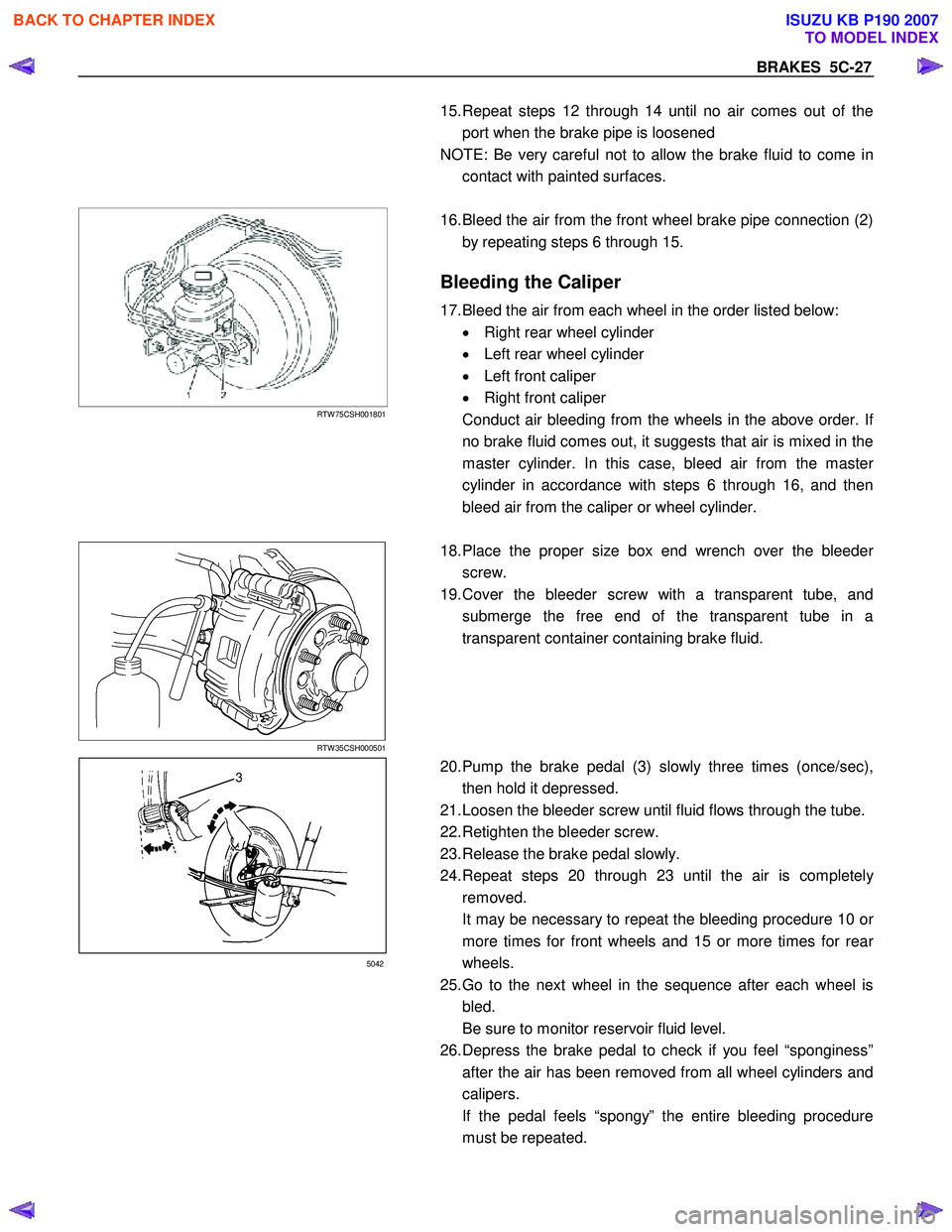
15. Repeat steps 12 through 14 until no air comes out of the
port when the brake pipe is loosened
NOTE: Be very careful not to allow the brake fluid to come in contact with painted surfaces.
RTW 75CSH001801
16. Bleed the air from the front wheel brake pipe connection (2)
by repeating steps 6 through 15.
Bleeding the Caliper
17. Bleed the air from each wheel in the order listed below: • Right rear wheel cylinder
• Left rear wheel cylinder
• Left front caliper
• Right front caliper
Conduct air bleeding from the wheels in the above order. I
f
no brake fluid comes out, it suggests that air is mixed in the
master cylinder. In this case, bleed air from the maste
r
cylinder in accordance with steps 6 through 16, and then
bleed air from the caliper or wheel cylinder.
RTW 35CSH000501
18. Place the proper size box end wrench over the bleeder
screw.
19. Cover the bleeder screw with a transparent tube, and submerge the free end of the transparent tube in a
transparent container containing brake fluid.
3
5042
20. Pump the brake pedal (3) slowly three times (once/sec),
then hold it depressed.
21. Loosen the bleeder screw until fluid flows through the tube.
22. Retighten the bleeder screw.
23. Release the brake pedal slowly.
24. Repeat steps 20 through 23 until the air is completel
y
removed.
It may be necessary to repeat the bleeding procedure 10 o
r
more times for front wheels and 15 or more times for rear
wheels.
25. Go to the next wheel in the sequence after each wheel is bled.
Be sure to monitor reservoir fluid level.
26. Depress the brake pedal to check if you feel “sponginess” after the air has been removed from all wheel cylinders and
calipers.
If the pedal feels “spongy” the entire bleeding procedure must be repeated.
BACK TO CHAPTER INDEX
TO MODEL INDEX
ISUZU KB P190 2007
Page 2069 of 6020
ENGINE MECHANICAL (C24SE) 6A-55
OPERATIONS ON REMOVED ENGINE
Crankshaft
Removal
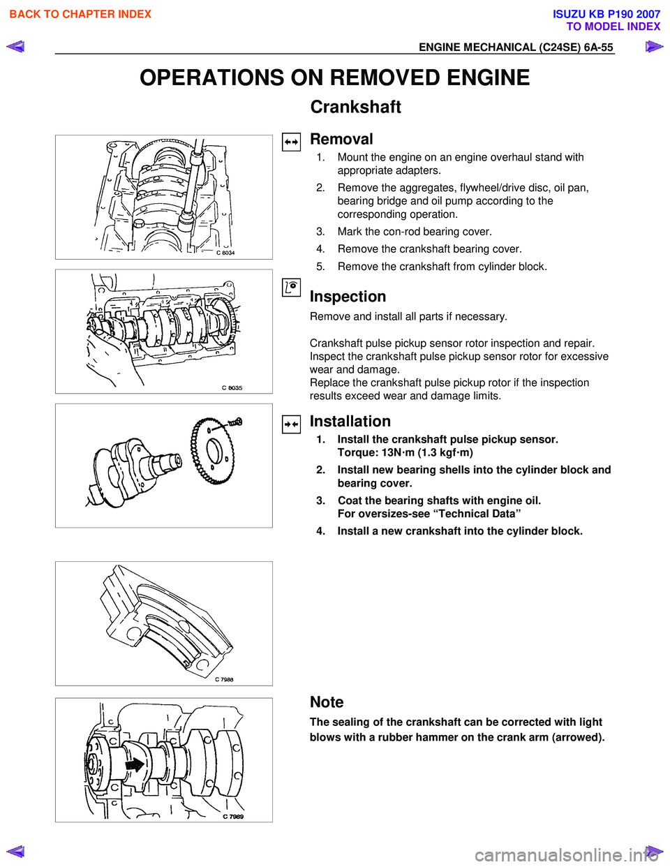
1. Mount the engine on an engine overhaul stand with appropriate adapters.
2. Remove the aggregates, flywheel/drive disc, oil pan, bearing bridge and oil pump according to the
corresponding operation.
3. Mark the con-rod bearing cover.
4. Remove the crankshaft bearing cover.
5. Remove the crankshaft from cylinder block.
Inspection
Remove and install all parts if necessary.
Crankshaft pulse pickup sensor rotor inspection and repair.
Inspect the crankshaft pulse pickup sensor rotor for excessive
wear and damage.
Replace the crankshaft pulse pickup rotor if the inspection
results exceed wear and damage limits.
Installation
1. Install the crankshaft pulse pickup sensor. Torque: 13N !
!!
!
m (1.3 kgf !
!!
!
m)
2. Install new bearing shells into the cylinder block and bearing cover.
3. Coat the bearing shafts with engine oil. For oversizes-see “Technical Data”
4. Install a new crankshaft into the cylinder block.
Note
The sealing of the crankshaft can be corrected with light
blows with a rubber hammer on the crank arm (arrowed).
BACK TO CHAPTER INDEX
TO MODEL INDEX
ISUZU KB P190 2007
Page 5639 of 6020
9A-4 SUPPLEMENTAL RESTRAINT SYSTEM
Service Precaution
WARNING: THIS VEHICLE HAS A SUPPLEMENTAL
RESTRAINT SYSTEM (SRS). REFER TO THE SRS
COMPONENT AND WIRING LOCATION VIEW IN
ORDER TO DETERMINE WHETHER YOU ARE
PERFORMING A SERVICE ON, OR NEAR, THE SRS
COMPONENTS OR THE SRS WIRING. WHEN YOU
ARE PERFORMING A SERVICE ON OR NEAR THE
SRS COMPONENTS OR THE SRS WIRING, REFER
TO THE SRS SERVICE INFORMATION. FAILURE
TO FOLLOW WARNINGS COULD RESULT IN
POSSIBLE AIR BAG DEPLOYMENT, PERSONAL
INJURY, OR OTHERWISE UNNECESSARY SRS
SYSTEM REPAIRS.
CAUTION: Always use the correct fastener in the
proper location. When you replace a fastener, use
ONLY the exact part number for that application.
ISUZU/GM will call out those fasteners that require
a replacement after removal. ISUZU/GM will also
call out the fasteners that require thread lockers o
r
thread sealant. UNLESS OTHERWISE SPECIFIED,
do not use supplemental coatings (paints,
greases, or other corrosion inhibitors) on threaded
fasteners or fastener joint interfaces. Generally,
such coatings adversely affect the fastener torque
and the joint clamping force, and may damage the
fastener. When you install fasteners, use the
correct tightening sequence and specifications.
Following these instructions can help you avoid
damage to parts and systems.
General Description
CAUTION: When fasteners are removed, always
reinstall them at the same location from which
they were removed. If a fastener needs to be
replaced, use the correct part number fastener fo
r
that application. If the correct part numbe
r
fastener is not available, a fastener of equal size
and strength (or stronger) may be used.
Fasteners that are not reused, and those requiring
thread locking compound will be called out. The
correct torque value must be used when installing
fasteners that require it. If the above conditions
are not followed, parts or system damage could
result.
Restraint Devices
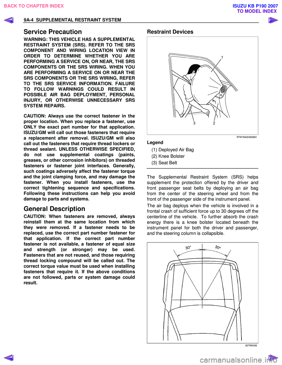
RTW 79ASH000801
Legend
(1) Deployed Air Bag
(2) Knee Bolster
(3) Seat Belt
The Supplemental Restraint System (SRS) helps
supplement the protection offered by the driver and
front passenger seat belts by deploying an air bag
from the center of the steering wheel and from the
front of the passenger side of the instrument panel.
The air bag deploys when the vehicle is involved in a
frontal crash of sufficient force up to 30 degrees off the
centerline of the vehicle. To further absorb the crash
energy there is a knee bolster located beneath the
instrument panel for both the driver and passenger,
and the steering column is collapsible.
827RW 005
BACK TO CHAPTER INDEX TO MODEL INDEXISUZU KB P190 2007
Page 5667 of 6020
9A-32 SUPPLEMENTAL RESTRAINT SYSTEM
Service Precautions for SRS
Component Service
CAUTION: When fasteners are removed, always
reinstall them at the same location from which
they were removed. If a fastener needs to be
replaced, use the correct part number fastener fo
r
that application. If the correct part number
fastener is not available, a fastener of equal size
and strength (or stronger) may be used. Fasteners
that are not reused, and those requiring a thread
locking compound will be called out. The correct
torque value must be used when installing
fasteners that require it. If the above conditions
are not followed, parts or system damage could
result.
WARNING: WHEN PERFORMING SERVICE ON OR
AROUND SRS COMPONENTS OR SRS WIRING,
FOLLOW THE PROCEDURES LISTED BELOW TO
TEMPORARILY DISABLE THE SRS. FAILURE TO
FOLLOW PROCEDURES COULD RESULT IN
POSSIBLE AIR BAG DEPLOYMENT, PERSONAL
INJURY OR OTHERWISE UNNEEDED SRS
REPAIRS.
The SRS control unit in the Driver–Passenger SRS
can maintain sufficient voltage to cause a deployment
for up to 15 seconds after the ignition switch is turned
“OFF,” the battery is disconnected, or the fuse
powering the SRS control unit is removed.
Many of the service procedures require removal of the
“SRS” fuse, and disconnection of the air bag assembl
y
from the deployment loop to avoid an accidental
deployment. If the air bag assembly is disconnected
from the deployment loop as noted in the “Disabling
the SRS” procedure that follows, service can begin
immediately without waiting for the 15 second time
period to expire.
Disabling The SRS
Removal
Turn the ignition switch to “OFF” and turn the steering
wheel so that the vehicle's wheels are pointing straight
ahead.
1. Remove the SRS fuse “SRS” from the left dash side lower fuse block or disconnect the battery.
2. Disconnect the yellow connector at the base o
f
steering column.
3. Remove the glove box assembly; Refer to “Passenger air bag assembly replacement” in this
section.
4. Disconnect the passenger air bag assembly yello
w
connector behind the glove box assembly.
CAUTION: With the “SRS” fuse removed and the
ignition switch to “ON,” the “SRS” warning lamp
will be “ON.” This is normal operation and does
not indicate an SRS malfunction.
Enabling The SRS
Installation
Turn the ignition switch to “LOCK” and remove the
key.
1. Connect the yellow connector passenger air bag assembly.
2. Install the glove box assembly. Refer to “Passenger Air Bag Assembly Replacement” in
this section.
3. Connect the yellow connector at the base of the steering column.
4. Install the “AIR BAG” fuse “SRS” to the left dash side lower fuse block or connect the battery.
Turn the ignition switch to “ON” and verify that the
“SRS” warning lamp flashes seven times and then
turns to “LOCK”. If it does not operate as described,
perform the “SRS Diagnostic System Check” in this
section.
Handling / Installation / Diagnosis
1. Air bag assembly should not be subjected to
temperatures above 65 °C (150 °F).
2.
Air bag assembly, and SRS control unit should not
be used if they have been dropped from a height
of 100 centimeters (3.28 feet) or more.
3. W hen a SRS control unit is replaced, it must be oriented with the arrow on the SRS control unit
pointing toward the front of the vehicle. It is ver
y
important for the SRS control unit to be located flat
on the mounting surface, parallel to the vehicle
datum line. It is important that the SRS control unit
mounting surface is free of any dirt or other foreign
material.
4. Do not apply power to the SRS unless all components are connected or a diagnostic chart
requests it, as this will set a diagnostic trouble
code.
5. The “SRS Diagnostic System Check” must be the starting point of any SRS diagnostics. The “SRS
Diagnostic System Check” will verify proper “SRS”
warning lamp operation and will lead you to the
correct chart to diagnose any SRS malfunctions.
Bypassing these procedures may result in
extended diagnostic time, incorrect diagnosis, and
incorrect parts replacements.
BACK TO CHAPTER INDEX TO MODEL INDEXISUZU KB P190 2007