bolt pattern ISUZU KB P190 2007 Workshop User Guide
[x] Cancel search | Manufacturer: ISUZU, Model Year: 2007, Model line: KB P190, Model: ISUZU KB P190 2007Pages: 6020, PDF Size: 70.23 MB
Page 2547 of 6020
Engine Mechanical – V6 Page 6A1–68
CAUTION
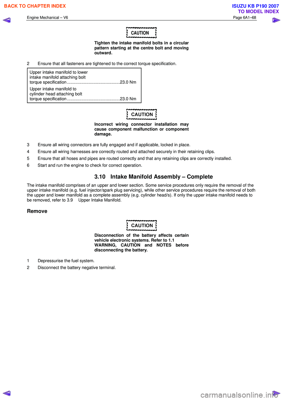
Tighten the intake manifold bolts in a circular
pattern starting at the centre bolt and moving
outward.
2 Ensure that all fasteners are tightened to the correct torque specification. Upper intake manifold to lower
intake manifold attaching bolt
torque specification ............................................23.0 Nm
Upper intake manifold to
cylinder head attaching bolt
torque specification ............................................23.0 Nm
Incorrect wiring connector installation may
cause component malfunction or component
damage.
3 Ensure all wiring connectors are fully engaged and if applicable, locked in place.
4 Ensure all wiring harnesses are correctly routed and attached securely in their retaining clips.
5 Ensure that all hoses and pipes are routed correctly and that any retaining clips are correctly installed.
6 Start and run the engine to check for correct operation.
3.10 Intake Manifold Assembly – Complete
The intake manifold comprises of an upper and lower section. Some service procedures only require the removal of the
upper intake manifold (e.g. fuel injector/spark plug servicing), while other service procedures require the removal of both
the upper and lower manifold as a complete assembly (e.g. cylinder head/s). If only the upper intake manifold needs to
be removed, refer to 3.9 Upper Intake Manifold.
Remove
Disconnection of the battery affects certain
vehicle electronic systems. Refer to 1.1
WARNING, CAUTION and NOTES before
disconnecting the battery.
1 Depressurise the fuel system.
2 Disconnect the battery negative terminal.
BACK TO CHAPTER INDEX
TO MODEL INDEX
ISUZU KB P190 2007
Page 2554 of 6020
Engine Mechanical – V6 Page 6A1–75
CAUTION
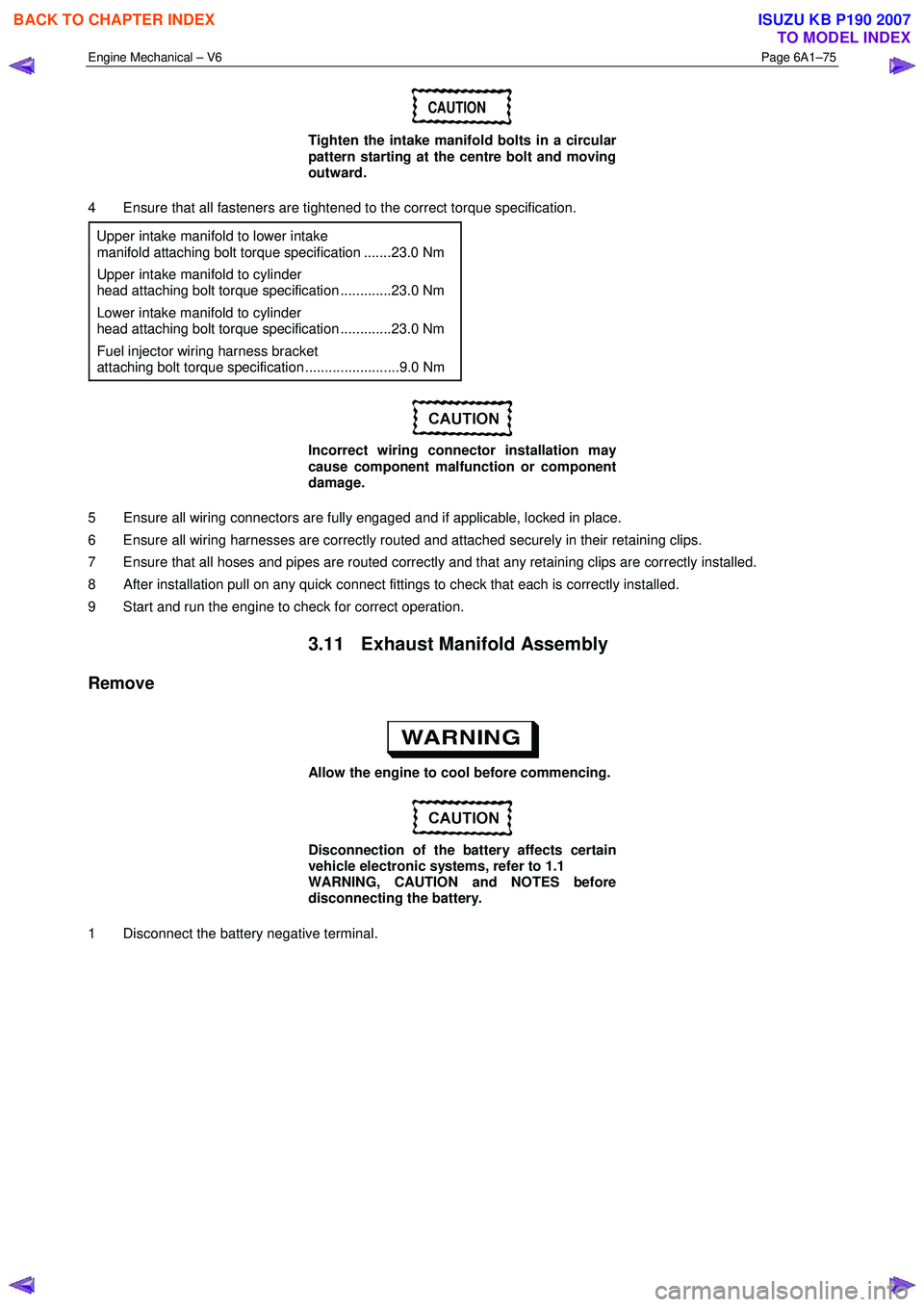
Tighten the intake manifold bolts in a circular
pattern starting at the centre bolt and moving
outward.
4 Ensure that all fasteners are tightened to the correct torque specification. Upper intake manifold to lower intake
manifold attaching bolt torque specification .......23.0 Nm
Upper intake manifold to cylinder
head attaching bolt torque specification .............23.0 Nm
Lower intake manifold to cylinder
head attaching bolt torque specification .............23.0 Nm
Fuel injector wiring harness bracket
attaching bolt torque specification ........................9.0 Nm
Incorrect wiring connector installation may
cause component malfunction or component
damage.
5 Ensure all wiring connectors are fully engaged and if applicable, locked in place.
6 Ensure all wiring harnesses are correctly routed and attached securely in their retaining clips.
7 Ensure that all hoses and pipes are routed correctly and that any retaining clips are correctly installed.
8 After installation pull on any quick connect fittings to check that each is correctly installed.
9 Start and run the engine to check for correct operation.
3.11 Exhaust Manifold Assembly
Remove
Allow the engine to cool before commencing.
Disconnection of the battery affects certain
vehicle electronic systems, refer to 1.1
WARNING, CAUTION and NOTES before
disconnecting the battery.
1 Disconnect the battery negative terminal.
BACK TO CHAPTER INDEX
TO MODEL INDEX
ISUZU KB P190 2007
Page 2805 of 6020
Engine Mechanical – V6 Page 6A1–28
Page 6A1–28
Pipe Joint Compound
• Pipe joint compound is a pliable sealer that does not comp letely harden. This type of sealer is used where two non-
rigid parts (such as pressed steel and ma chined surfaces) are assembled together.
• Do not use pipe joint compound in areas where extreme temperatures are expected. These areas include the
exhaust manifold, head gasket, or other surfaces where gasket eliminator is specified.
• Follow all safety recommendations and di rections that are on the container.
• To remove the sealant or the gasket mate rial, refer to Replacing Engine Gaskets.
• Apply the pipe joint compound to a clean surface. Use a bead size or quantity as specified in the procedure. Run
the bead to the inside of any bolt holes. Do not allow the s ealer to enter any blind threaded holes as it may prevent
the bolt from clamping correctly or caus e component damage when the bolt is tightened.
• Apply a continuous bead of pipe joint compound to one seali ng surface. Sealing surfaces to be resealed must be
clean and dry.
• Tighten the bolts to the correct torque specification. Do not over-tighten.
Separating Parts
CAUTION
Many internal engine components will
develop specific wear patterns on their
friction surfaces. When disassembling the
engine, internal components must be
separated, marked and organised in a way to
ensure reinstallation in their original location
and position.
Separate, mark, or organise the following components:
• Piston and the piston pin.
• Piston to the specific cylinder bore.
• Piston rings to the specific piston.
• Connecting rod to the crankshaft journal.
• Connecting rod to the bearing cap.
• Crankshaft main and connecting rod bearings.
• Camshaft and rocker arms.
• Rocker arms and stationary hydraulic lash adjusters to cylinder head location.
• Valve to the valve guide.
• Valve spring and shim to the cylinder head location.
• Engine block main bearing cap location and direction.
• Oil pump drive and driven gears.
Tools and Equipment
Special tools are listed and illustrated throughout this Section with a complete listing at the end, refer to 7 Special Tools.
These tools (or their equivalents) are specially designed to quickly and safely accomplish the operations for which they
are intended. The use of these special tools will also minimise possible damage to engine components. Some precision
measuring tools are required for inspec tion of certain critical components. A commercially available torque wrench and
torque angle wrench, Tool No. EN-7115 are required for the correct tightening of various fasteners.
To correctly service the engine assembly, the following items should be readily available:
• Approved eye protection and safety gloves.
• A clean, well-lit, work area.
• A suitable parts cleaning tank.
• A compressed air supply.
• Trays or storage containers to keep parts and fasteners organised.
• An adequate set of hand tools.
• Approved engine repair stand.
• An approved engine lifting device that will adequatel y support the weight of the components.
BACK TO CHAPTER INDEX
TO MODEL INDEX
ISUZU KB P190 2007
Page 2859 of 6020
Engine Mechanical – V6 Page 6A1–82
Page 6A1–82
Reinstall
Reinstallation of the upper intake manifold and the upper and lower intake manifold assembly is the reverse of the
removal procedure, noting the following:
1 Only new gaskets are to be fitted betw een the upper and lower intake manifolds.
CAUTION
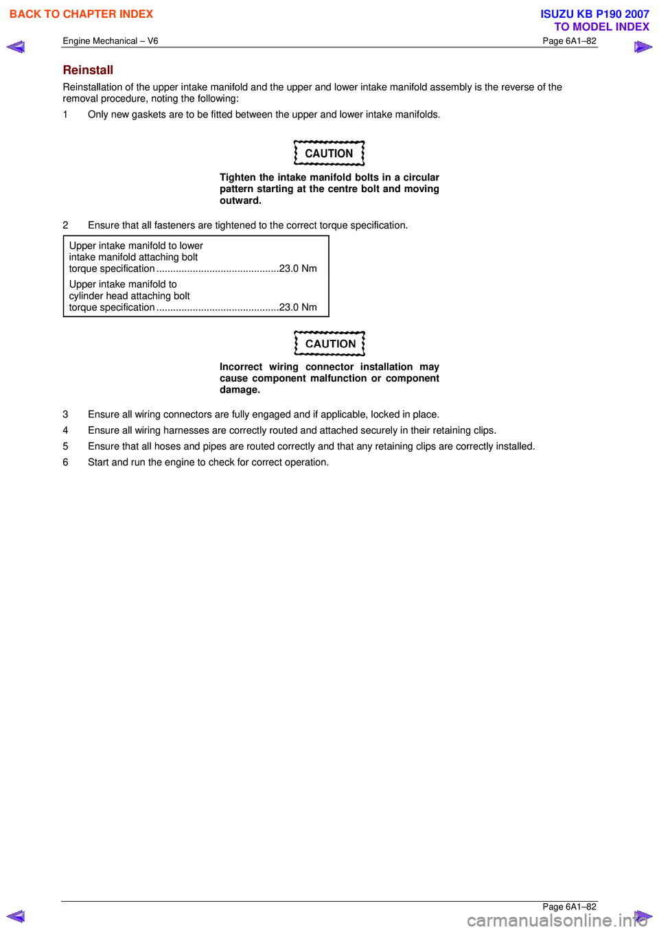
Tighten the intake manifold bolts in a circular
pattern starting at the centre bolt and moving
outward.
2 Ensure that all fasteners are tightened to the correct torque specification.
Upper intake manifold to lower
intake manifold attaching bolt
torque specificat ion ............................................ 23.0 Nm
Upper intake manifold to
cylinder head attaching bolt
torque specification ............................................ 23.0 Nm
Incorrect wiring connector installation may
cause component malfunction or component
damage.
3 Ensure all wiring connectors are fully engaged and if applicable, locked in place.
4 Ensure all wiring harnesses are correctly routed and attached securely in their retaining clips.
5 Ensure that all hoses and pipes ar e routed correctly and that any retaining clips are correctly installed.
6 Start and run the engine to c heck for correct operation.
BACK TO CHAPTER INDEX
TO MODEL INDEX
ISUZU KB P190 2007
Page 2866 of 6020
Engine Mechanical – V6 Page 6A1–89
Page 6A1–89
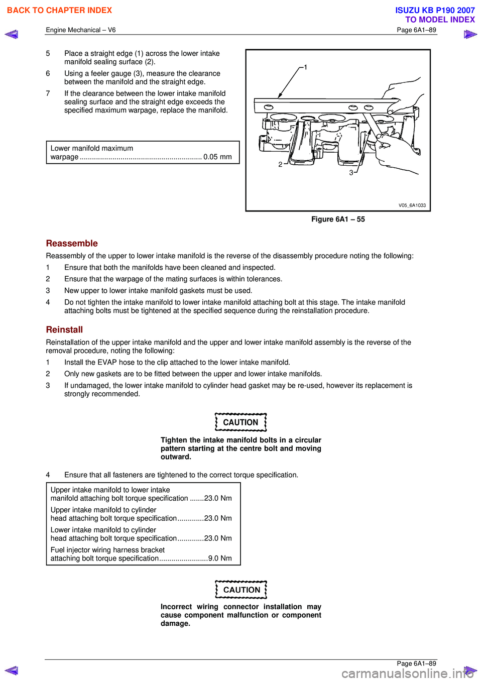
5 Place a straight edge (1) across the lower intake
manifold sealing surface (2).
6 Using a feeler gauge (3), measure the clearance
between the manifold and the straight edge.
7 If the clearance between the lower intake manifold sealing surface and the straight edge exceeds the
specified maximum warpage, replace the manifold.
Lower manifold maximum
warpage ............................................................ 0.05 mm
Figure 6A1 – 55
Reassemble
Reassembly of the upper to lower intake manifold is the reverse of the disassembly procedure noting the following:
1 Ensure that both the manifo lds have been cleaned and inspected.
2 Ensure that the warpage of the mati ng surfaces is within tolerances.
3 New upper to lower intake m anifold gaskets must be used.
4 Do not tighten the intake manifold to lower intake manifold attaching bolt at this stage. The intake manifold
attaching bolts must be tightened at the specif ied sequence during the reinstallation procedure.
Reinstall
Reinstallation of the upper intake manifold and the upper and lower intake manifo ld assembly is the reverse of the
removal procedure, noting the following:
1 Install the EVAP hose to the clip atta ched to the lower intake manifold.
2 Only new gaskets are to be fitted betw een the upper and lower intake manifolds.
3 If undamaged, the lower intake manifold to cylinder head gasket may be re-used, however its replacement is
strongly recommended.
CAUTION
Tighten the intake manifold bolts in a circular
pattern starting at the centre bolt and moving
outward.
4 Ensure that all fasteners are tightened to the correct torque specification.
Upper intake manifold to lower intake
manifold attaching bolt torq ue specification .......23.0 Nm
Upper intake manifold to cylinder
head attaching bolt torque specification .............23.0 Nm
Lower intake manifold to cylinder
head attaching bolt torque specification .............23.0 Nm
Fuel injector wiring harness bracket
attaching bolt torque specification ........................9.0 Nm
Incorrect wiring connector installation may
cause component malfunction or component
damage.
BACK TO CHAPTER INDEX
TO MODEL INDEX
ISUZU KB P190 2007
Page 3943 of 6020
Automatic Transmission – 4L60E – On-vehicle Servicing Page 7C4–30
12 Road test until the transmission has reached operating temperature. Re-check the fluid level and for any fluid leaks
from the oil pan area, refer to 2.1 Transmission Fluid.
3.14 Control Valve Body
Remove
1 Partially remove the control valve body harness until it hangs from the pass-thru connector, refer to
3.13 Control Valve Body Harness.
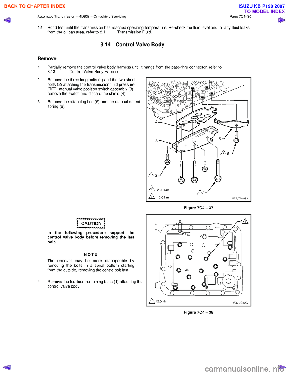
2 Remove the three long bolts (1) and the two short bolts (2) attaching the transmission fluid pressure
(TFP) manual valve position switch assembly (3),
remove the switch and discard the shield (4).
3 Remove the attaching bolt (5) and the manual detent spring (6).
Figure 7C4 – 37
In the following procedure support the
control valve body before removing the last
bolt.
NOTE
The removal may be more manageable by
removing the bolts in a spiral pattern starting
from the outside, removing the centre bolt last.
4 Remove the fourteen remaining bolts (1) attaching the control valve body.
Figure 7C4 – 38
BACK TO CHAPTER INDEX
TO MODEL INDEX
ISUZU KB P190 2007
Page 3947 of 6020
Automatic Transmission – 4L60E – On-vehicle Servicing Page 7C4–34
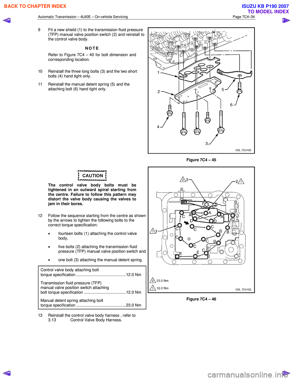
9 Fit a new shield (1) to the transmission fluid pressure
(TFP) manual valve position switch (2) and reinstall to
the control valve body.
NOTE
Refer to Figure 7C4 – 40 for bolt dimension and
corresponding location.
10 Reinstall the three long bolts (3) and the two short bolts (4) hand tight only.
11 Reinstall the manual detent spring (5) and the attaching bolt (6) hand tight only.
Figure 7C4 – 45
The control valve body bolts must be
tightened in an outward spiral starting from
the centre. Failure to follow this pattern may
distort the valve body causing the valves to
jam in their bores.
12 Follow the sequence starting from the centre as shown by the arrows to tighten the following bolts to the
correct torque specification:
• fourteen bolts (1) attaching the control valve
body,
• five bolts (2) attaching the transmission fluid
pressure (TFP) manual valve position switch and
• one bolt (3) attaching the manual detent spring.
Control valve body attaching bolt
torque specification ............................................ 12.0 Nm
Transmission fluid pressure (TFP) manual valve position switch attaching bolt torque specification ..................................... 12.0 Nm
Manual detent spring attaching bolt torque specification ............................................ 23.0 Nm
13 Reinstall the control valve body harness , refer to 3.13 Control Valve Body Harness.
Figure 7C4 – 46
BACK TO CHAPTER INDEX
TO MODEL INDEX
ISUZU KB P190 2007