engine overheat ISUZU KB P190 2007 Workshop User Guide
[x] Cancel search | Manufacturer: ISUZU, Model Year: 2007, Model line: KB P190, Model: ISUZU KB P190 2007Pages: 6020, PDF Size: 70.23 MB
Page 1752 of 6020

ENGINE CONTROL SYSTEM (4JK1/4JJ1) 6E-135
DTC P0217 (Flash Code 542)
Circuit Description
The engine coolant temperature (ECT) sensor is
installed to the thermostat housing. The ECT sensor is
a variable resistor and it measures the temperature of
the engine coolant. If the ECM detects an excessive
high coolant temperature, this DTC will set.
Condition for Running the DTC • DTCs P0116, P0117 and P0118 are not set.
• The battery voltage is more than 9 volts.
• The ignition switch is ON.
• The engine is running.
Condition for Setting the DTC • The ECM detects that the engine coolant temperature is more than 110 °C (230 °F) for 5
seconds.
Action Taken When the DTC Sets • The ECM will not illuminate the MIL or SVS lamp. Refer to DTC Type Definitions for Action Taken
When the DTC Sets - Type D. Condition for Clearing the DTC
• Refer to DTC Type Definitions for Condition for Clearing the DTC - Type D.
Diagnostic Aids • After starting the engine, the ECT should rise steadily to about 80 to 85 °C (176 to 185 °F) then
stabilize when the thermostat opens.
• Use the Temperature vs. Resistance table to test the ECT sensor at various temperature levels to
evaluate the possibility of a skewed sensor. A
skewed sensor could result in poor driveability
concerns.
• The Total Engine Coolant Overtemperature Events parameter on scan tool indicates number of
overheat events.
Notice: • This DTC is caused by an engine overheat condition (e.g. low engine coolant level). Since this
DTC does not illuminate any lamps, clear the DTC
and ensure there are no signs of engine damage.
Excessive engine overheat may damage internal
engine components.
Circuit/ System Testing DTC P0217
Step Action Value(s)Yes No
1 Did you perform the Diagnostic System Check -
Engine Controls? —
Go to Step 2 Go to Diagnostic
System Check -
Engine Controls
2 1. Install a scan tool.
2. Turn OFF the ignition for 30 seconds.
3. Start the engine.
4. Monitor the DTC Information with a scan tool.
Is DTC P0117 also set? —
Go to DTC P0117 Go to Step 3
3 1. Test the engine cooling system for the
following condition. Refer to diagnosis of the
engine cooling system section for testing.
• Engine coolant level
• Engine coolant leakage
• Cooling fan belt slippage
• Cooling fan clutch working
• Thermostat working
• Water pump working
• Radiator clogging
2. Repair or replace as necessary.
Did you find and correct the condition? —
Go to Step 7 Go to Step 4
4 Start the engine and wait until engine is fully warm
upped while observing the Coolant Temperature
parameter with a scan tool.
Does the scan tool indicate more than the specified
value? 11 0
°C (230 °F)
Go to Step 6 Go to Step 5
BACK TO CHAPTER INDEX
TO MODEL INDEX
ISUZU KB P190 2007
Page 1753 of 6020

6E-136 ENGINE CONTROL SYSTEM (4JK1/4JJ1)
5Ask the driver if overheat is caused by low engine
coolant level, etc.
If engine overheat has experienced, the engine
must be inspected and repaired as necessary.
Did you complete the action? —
Go to Step 7
—
61. Test the engine coolant temperature (ECT)
sensor at various temperature levels to
evaluate the possibility of a skewed sensor.
2. Replace the ECT sensor as necessary.
Did you find and correct the condition? —
Go to Step 7 Go to Diagnostic
Aids
7 1. Reconnect all previously disconnected
harness connector(s).
2. Clear the DTCs with a scan tool.
3. Turn OFF the ignition for 30 seconds.
4. Start the engine and wait until engine is fully warm upped while observing the Coolant
Temperature parameter with a scan tool.
Does the scan tool indicate more than the specified
value? 11 0
°C (230 °F)
Go to Step 2 Go to Step 8
8 Observe the DTC Information with a scan tool.
Are there any DTCs that you have not diagnosed? —
Go to DTC List System OK
Step
Action Value(s)Yes No
BACK TO CHAPTER INDEX
TO MODEL INDEX
ISUZU KB P190 2007
Page 1954 of 6020
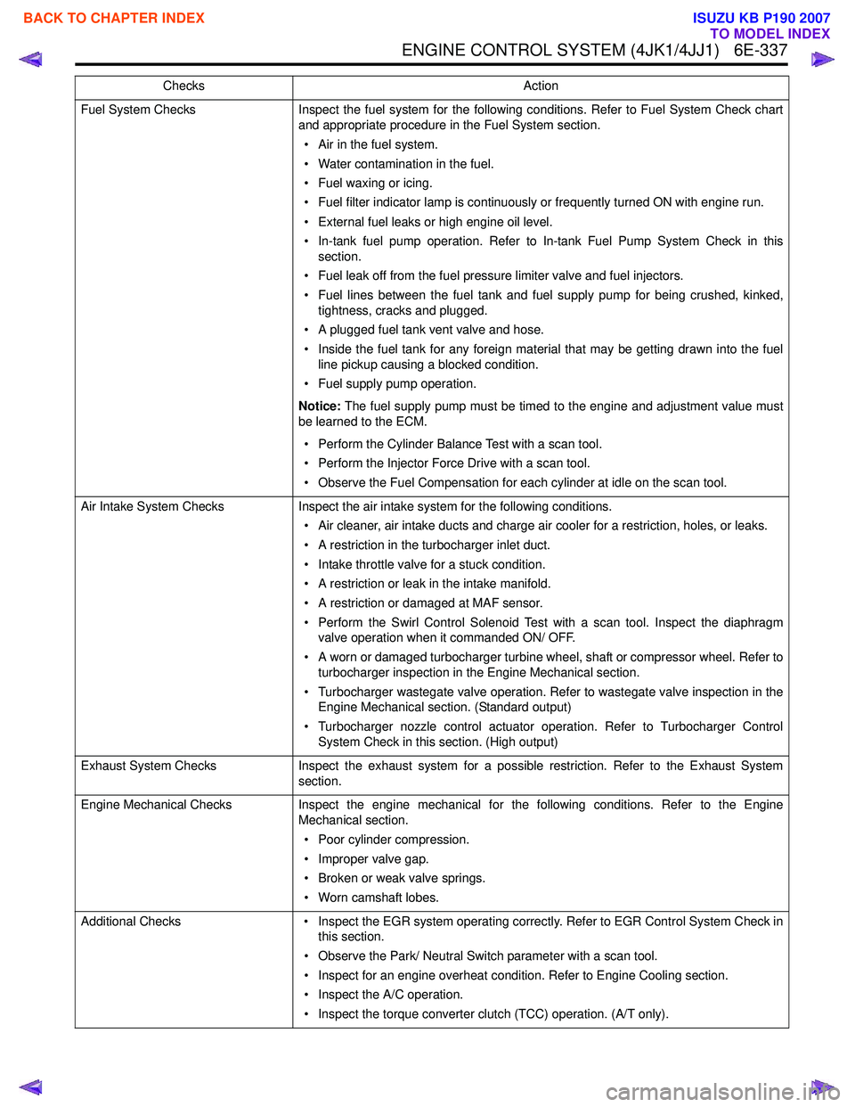
ENGINE CONTROL SYSTEM (4JK1/4JJ1) 6E-337
Fuel System ChecksInspect the fuel system for the following conditions. Refer to Fuel System Check chart
and appropriate procedure in the Fuel System section.
• Air in the fuel system.
• Water contamination in the fuel.
• Fuel waxing or icing.
• Fuel filter indicator lamp is continuously or frequently turned ON with engine run.
• External fuel leaks or high engine oil level.
• In-tank fuel pump operation. Refer to In-tank Fuel Pump System Check in this section.
• Fuel leak off from the fuel pressure limiter valve and fuel injectors.
• Fuel lines between the fuel tank and fuel supply pump for being crushed, kinked, tightness, cracks and plugged.
• A plugged fuel tank vent valve and hose.
• Inside the fuel tank for any foreign material that may be getting drawn into the fuel line pickup causing a blocked condition.
• Fuel supply pump operation.
Notice: The fuel supply pump must be timed to the engine and adjustment value must
be learned to the ECM.
• Perform the Cylinder Balance Test with a scan tool.
• Perform the Injector Force Drive with a scan tool.
• Observe the Fuel Compensation for each cylinder at idle on the scan tool.
Air Intake System Checks Inspect the air intake system for the following conditions.
• Air cleaner, air intake ducts and charge air cooler for a restriction, holes, or leaks.
• A restriction in the turbocharger inlet duct.
• Intake throttle valve for a stuck condition.
• A restriction or leak in the intake manifold.
• A restriction or damaged at MAF sensor.
• Perform the Swirl Control Solenoid Test with a scan tool. Inspect the diaphragm valve operation when it commanded ON/ OFF.
• A worn or damaged turbocharger turbine wheel, shaft or compressor wheel. Refer to turbocharger inspection in the Engine Mechanical section.
• Turbocharger wastegate valve operation. Refer to wastegate valve inspection in the Engine Mechanical section. (Standard output)
• Turbocharger nozzle control actuator operation. Refer to Turbocharger Control System Check in this section. (High output)
Exhaust System Checks Inspect the exhaust system for a possible restriction. Refer to the Exhaust System
section.
Engine Mechanical Checks Inspect the engine mechanical for the following conditions. Refer to the Engine
Mechanical section.
• Poor cylinder compression.
• Improper valve gap.
• Broken or weak valve springs.
• Worn camshaft lobes.
Additional Checks • Inspect the EGR system operating correctly. Refer to EGR Control System Check in
this section.
• Observe the Park/ Neutral Switch parameter with a scan tool.
• Inspect for an engine overheat condition. Refer to Engine Cooling section.
• Inspect the A/C operation.
• Inspect the torque converter clutch (TCC) operation. (A/T only).
Checks
Action
BACK TO CHAPTER INDEX
TO MODEL INDEX
ISUZU KB P190 2007
Page 1956 of 6020
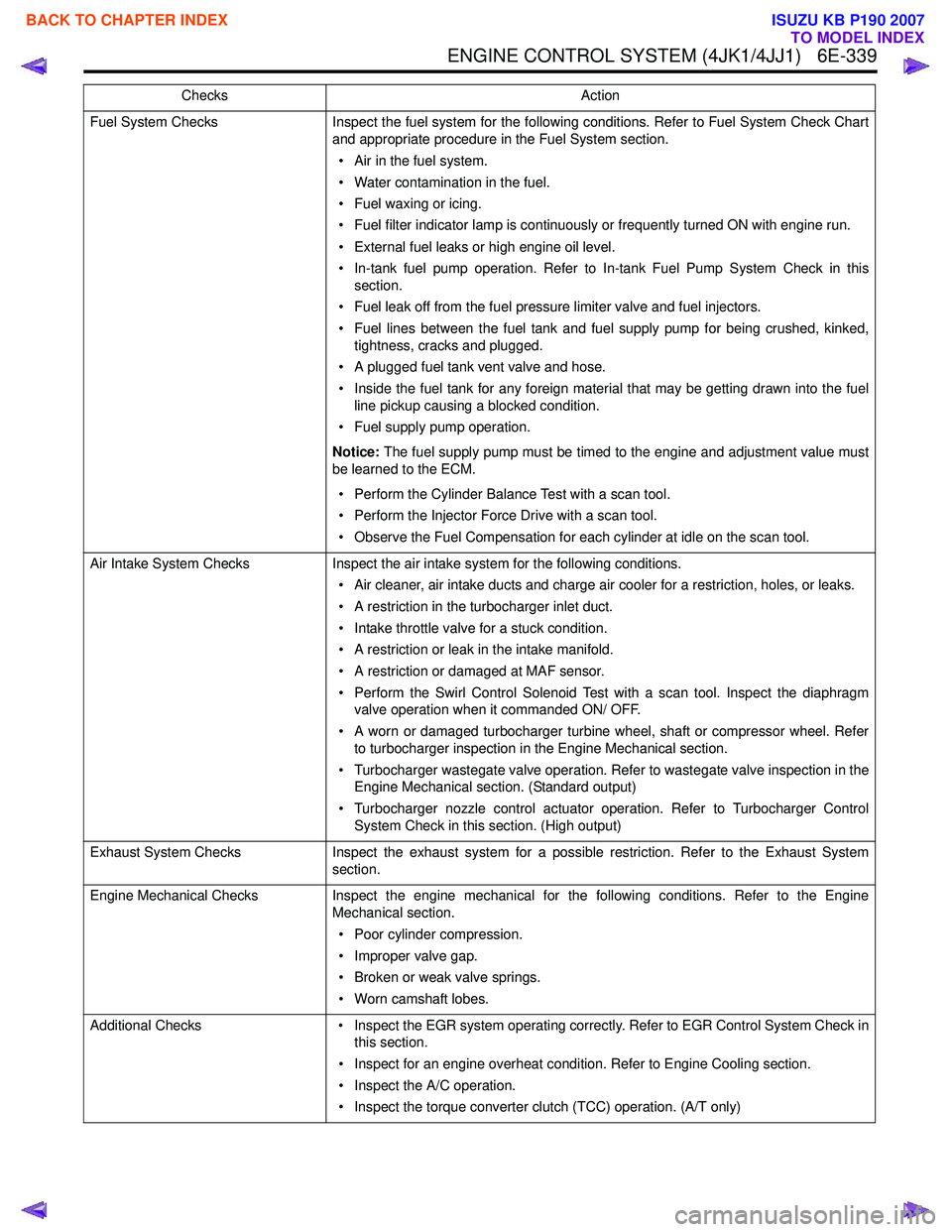
ENGINE CONTROL SYSTEM (4JK1/4JJ1) 6E-339
Fuel System ChecksInspect the fuel system for the following conditions. Refer to Fuel System Check Chart
and appropriate procedure in the Fuel System section.
• Air in the fuel system.
• Water contamination in the fuel.
• Fuel waxing or icing.
• Fuel filter indicator lamp is continuously or frequently turned ON with engine run.
• External fuel leaks or high engine oil level.
• In-tank fuel pump operation. Refer to In-tank Fuel Pump System Check in this section.
• Fuel leak off from the fuel pressure limiter valve and fuel injectors.
• Fuel lines between the fuel tank and fuel supply pump for being crushed, kinked, tightness, cracks and plugged.
• A plugged fuel tank vent valve and hose.
• Inside the fuel tank for any foreign material that may be getting drawn into the fuel line pickup causing a blocked condition.
• Fuel supply pump operation.
Notice: The fuel supply pump must be timed to the engine and adjustment value must
be learned to the ECM.
• Perform the Cylinder Balance Test with a scan tool.
• Perform the Injector Force Drive with a scan tool.
• Observe the Fuel Compensation for each cylinder at idle on the scan tool.
Air Intake System Checks Inspect the air intake system for the following conditions.
• Air cleaner, air intake ducts and charge air cooler for a restriction, holes, or leaks.
• A restriction in the turbocharger inlet duct.
• Intake throttle valve for a stuck condition.
• A restriction or leak in the intake manifold.
• A restriction or damaged at MAF sensor.
• Perform the Swirl Control Solenoid Test with a scan tool. Inspect the diaphragm valve operation when it commanded ON/ OFF.
• A worn or damaged turbocharger turbine wheel, shaft or compressor wheel. Refer to turbocharger inspection in the Engine Mechanical section.
• Turbocharger wastegate valve operation. Refer to wastegate valve inspection in the Engine Mechanical section. (Standard output)
• Turbocharger nozzle control actuator operation. Refer to Turbocharger Control System Check in this section. (High output)
Exhaust System Checks Inspect the exhaust system for a possible restriction. Refer to the Exhaust System
section.
Engine Mechanical Checks Inspect the engine mechanical for the following conditions. Refer to the Engine
Mechanical section.
• Poor cylinder compression.
• Improper valve gap.
• Broken or weak valve springs.
• Worn camshaft lobes.
Additional Checks • Inspect the EGR system operating correctly. Refer to EGR Control System Check in
this section.
• Inspect for an engine overheat condition. Refer to Engine Cooling section.
• Inspect the A/C operation.
• Inspect the torque converter clutch (TCC) operation. (A/T only)
Checks
Action
BACK TO CHAPTER INDEX
TO MODEL INDEX
ISUZU KB P190 2007
Page 2008 of 6020
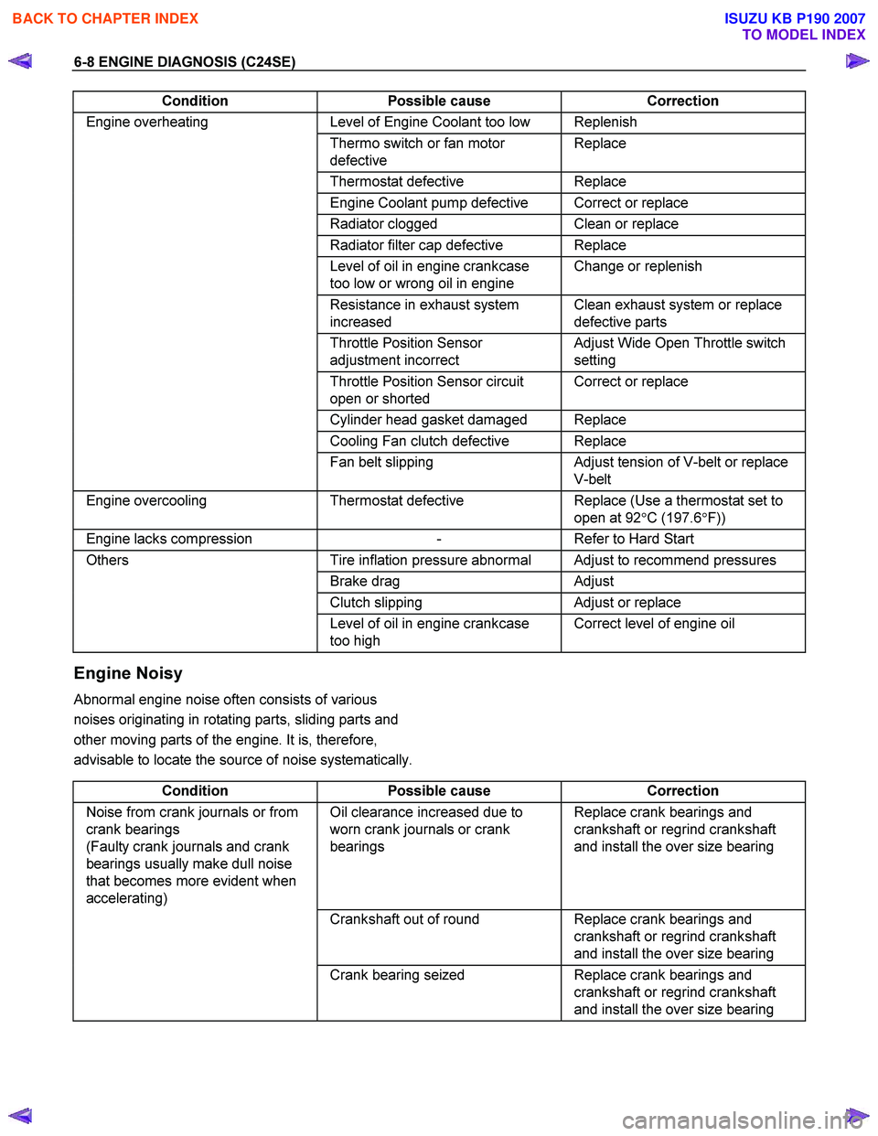
6-8 ENGINE DIAGNOSIS (C24SE)
Condition Possible cause Correction
Engine overheating Level of Engine Coolant too low Replenish
Thermo switch or fan motor
defective Replace
Thermostat
defective Replace
Engine Coolant pump defective Correct or replace
Radiator clogged Clean or replace
Radiator filter cap defective Replace
Level of oil in engine crankcase
too low or wrong oil in engine Change or replenish
Resistance in exhaust system
increased Clean exhaust system or replace
defective parts
Throttle Position Sensor
adjustment incorrect Adjust Wide Open Throttle switch
setting
Throttle Position Sensor circuit
open or shorted Correct or replace
Cylinder head gasket damaged Replace
Cooling Fan clutch defective Replace
Fan belt slipping Adjust tension of V-belt or replace
V-belt
Engine overcooling Thermostat defective Replace (Use a thermostat set to
open at 92 °C (197.6 °F))
Engine lacks compression - Refer to Hard Start
Others Tire inflation pressure abnormal Adjust to recommend pressures
Brake drag Adjust
Clutch slipping Adjust or replace
Level of oil in engine crankcase
too high Correct level of engine oil
Engine Noisy
Abnormal engine noise often consists of various
noises originating in rotating parts, sliding parts and
other moving parts of the engine. It is, therefore,
advisable to locate the source of noise systematically.
Condition Possible cause Correction
Noise from crank journals or from
crank bearings
(Faulty crank journals and crank
bearings usually make dull noise
that becomes more evident when
accelerating) Oil clearance increased due to
worn crank journals or crank
bearings Replace crank bearings and
crankshaft or regrind crankshaft
and install the over size bearing
Crankshaft out of round Replace crank bearings and
crankshaft or regrind crankshaft
and install the over size bearing
Crank bearing seized Replace crank bearings and
crankshaft or regrind crankshaft
and install the over size bearing
BACK TO CHAPTER INDEX
TO MODEL INDEX
ISUZU KB P190 2007
Page 2010 of 6020
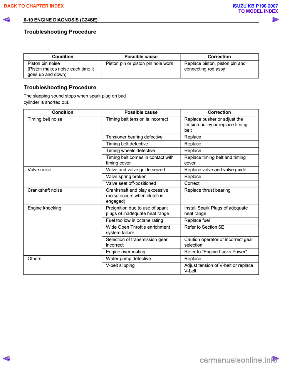
6-10 ENGINE DIAGNOSIS (C24SE)
Troubleshooting Procedure
Condition Possible cause Correction
Piston pin noise
(Piston makes noise each time it
goes up and down) Piston pin or piston pin hole worn Replace piston, piston pin and
connecting rod assy
Troubleshooting Procedure
The slapping sound stops when spark plug on bad
cylinder is shorted out.
Condition Possible cause Correction
Timing belt noise Timing belt tension is incorrect Replace pusher or adjust the
tension pulley or replace timing
belt
Tensioner bearing defective Replace
Timing belt defective Replace
Timing wheels defective Replace
Timing belt comes in contact with
timing cover Replace timing belt and timing
cover
Valve noise Valve and valve guide seized Replace valve and valve guide
Valve spring broken Replace
Valve seat off-positioned Correct
Crankshaft noise Crankshaft end play excessive
(noise occurs when clutch is
engaged) Replace thrust bearing
Engine knocking
Preignition due to use of spark
plugs of inadequate heat range Install Spark Plugs of adequate
heat range
Fuel too low in octane rating Replace fuel
Wide Open Throttle enrichment
system failure Refer to Section 6E
Selection of transmission gear
incorrect Caution operator or incorrect gear
selection
Engine overheating Refer to "Engine Lacks Power"
Others Water pump defective Replace
V-belt slipping Adjust tension of V-belt or replace
V-belt
BACK TO CHAPTER INDEX
TO MODEL INDEX
ISUZU KB P190 2007
Page 2109 of 6020
ENGINE COOLING 6B-5
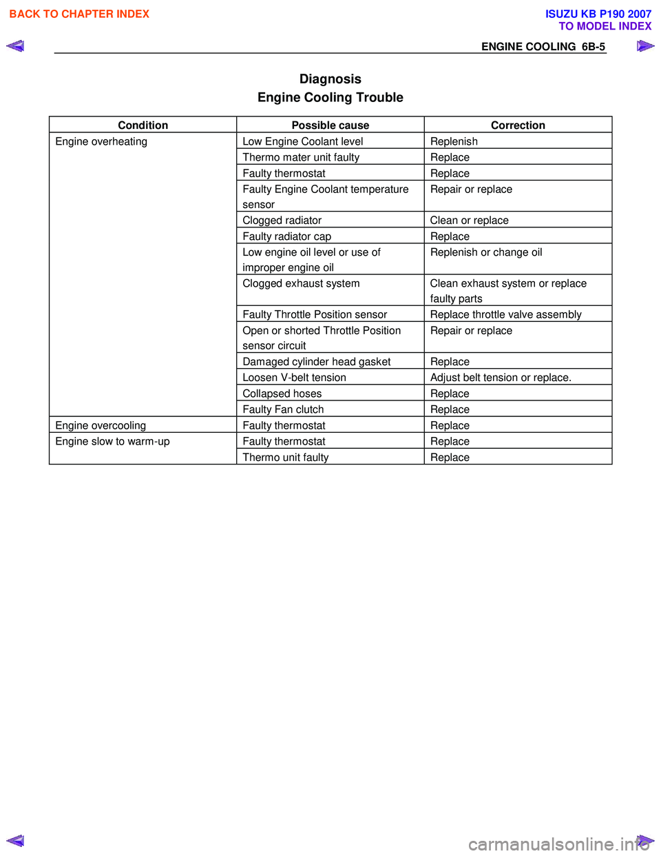
Diagnosis
Engine Cooling Trouble
Condition Possible cause Correction
Engine overheating Low Engine Coolant level Replenish
Thermo mater unit faulty Replace
Faulty thermostat Replace
Faulty Engine Coolant temperature
sensor Repair or replace
Clogged radiator Clean or replace
Faulty radiator cap Replace
Low engine oil level or use of
improper engine oil Replenish or change oil
Clogged exhaust system Clean exhaust system or replace
faulty parts
Faulty Throttle Position sensor Replace throttle valve assembly
Open or shorted Throttle Position
sensor circuit Repair or replace
Damaged cylinder head gasket Replace
Loosen V-belt tension Adjust belt tension or replace.
Collapsed hoses Replace
Faulty Fan clutch Replace
Engine overcooling Faulty thermostat Replace
Engine slow to warm-up Faulty thermostat Replace
Thermo unit faulty Replace
BACK TO CHAPTER INDEX
TO MODEL INDEX
ISUZU KB P190 2007
Page 2116 of 6020
6B-12 ENGINE COOLING
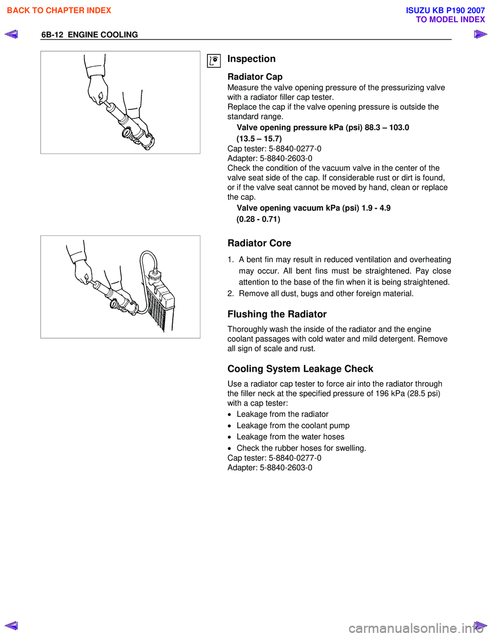
Inspection
Radiator Cap
Measure the valve opening pressure of the pressurizing valve
with a radiator filler cap tester.
Replace the cap if the valve opening pressure is outside the
standard range.
Valve opening pressure kPa (psi) 88.3 – 103.0
(13.5 – 15.7)
Cap tester: 5-8840-0277-0
Adapter: 5-8840-2603-0
Check the condition of the vacuum valve in the center of the
valve seat side of the cap. If considerable rust or dirt is found,
or if the valve seat cannot be moved by hand, clean or replace
the cap.
Valve opening vacuum kPa (psi) 1.9 - 4.9
(0.28 - 0.71)
Radiator Core
1. A bent fin may result in reduced ventilation and overheating
may occur. All bent fins must be straightened. Pay close
attention to the base of the fin when it is being straightened.
2. Remove all dust, bugs and other foreign material.
Flushing the Radiator
Thoroughly wash the inside of the radiator and the engine
coolant passages with cold water and mild detergent. Remove
all sign of scale and rust.
Cooling System Leakage Check
Use a radiator cap tester to force air into the radiator through
the filler neck at the specified pressure of 196 kPa (28.5 psi)
with a cap tester:
• Leakage from the radiator
• Leakage from the coolant pump
• Leakage from the water hoses
• Check the rubber hoses for swelling.
Cap tester: 5-8840-0277-0
Adapter: 5-8840-2603-0
BACK TO CHAPTER INDEX
TO MODEL INDEX
ISUZU KB P190 2007
Page 2224 of 6020
6E–54 ENGINE DRIVEABILITY AND EMISSIONS
GENERAL DESCRIPTION FOR ELECTRIC
IGNITION SYSTEM
The engine use two ignition coils, one per two cylinders.
A two wire connector provides a battery voltage primary
supply through the ignition fuse.
The ignition control spark timing is the ECM’s method of
controlling the spark advance and the ignition dwell.
The ignition control spark advance and the ignition dwell
are calculated by the ECM using the following inputs.
• Engine speed
• Crankshaft position (CKP) sensor
• Engine coolant temperature (ECT) sensor
• Throttle position sensor
• Vehicle speed sensor
• ECM and ignition system supply voltage
Ignition coil works to generate only the secondary
voltage be receiving the primary voltage from ECM.
The primary voltage is generated at the coil driver
located in the ECM. The coil driver generate the primary
voltage based on the crankshaft position signal. In
accordance with the crankshaft position signal, ignition
coil driver determines the adequate ignition timing and
also cylinder number to ignite.
Ignition timing is determined the coolant temperature,
intake air temperature, engine speed, engine load,
knock sensor signal, etc.
Spark Plug
Although worn or dirty spark plugs may give satisfactory
operation at idling speed, they frequently fail at higher
engine speeds. Faulty spark plugs may cause poor fuel
economy, power loss, loss of speed, hard starting and
generally poor engine performance. Follow the
scheduled maintenance service recommendations to
ensure satisfactory spark plug performance. Refer to
Maintenance and Lubrication .
Normal spark plug operation will result in brown to
grayish-tan deposits appearing on the insulator portion
of the spark plug. A small amount of red-brown, yellow,
and white powdery material may also be present on the
insulator tip around the center electrode. These
deposits are normal combustion by-products of fuels
and lubricating oils with additives. Some electrode wear
will also occur. Engines which are not running properly
are often referred to as “misfiring.” This means the
ignition spark is not igniting the air/fuel mixture at the
proper time. While other ignition and fuel system causes
must also be considered, possible causes include
ignition system conditions which allow the spark voltage
to reach ground in some other manner than by jumping
across the air gap at the tip of the spark plug, leaving
the air/fuel mixture unburned. Misfiring may also occur
when the tip of the spark plug becomes overheated and
ignites the mixture before the spark jumps. This is
referred to as “pre-ignition.”
Spark plugs may also misfire due to fouling, excessive
gap, or a cracked or broken insulator. If misfiring occurs before the recommended replacement interval, locate
and correct the cause.
Carbon fouling of the spark plug is indicated by dry,
black carbon (soot) deposits on the portion of the spark
plug in the cylinder. Excessive idling and slow speeds
under light engine loads can keep the spark plug
temperatures so low that these deposits are not burned
off. Very rich fuel mixtures or poor ignition system output
may also be the cause. Refer to DTC P1167.
Oil fouling of the spark plug is indicated by wet oily
deposits on the portion of the spark plug in the cylinder,
usually with little electrode wear. This may be caused by
oil during break-in of new or newly overhauled engines.
Deposit fouling of the spark plug occurs when the
normal red-brown, yellow or white deposits of
combustion by-products become sufficient to cause
misfiring. In some cases, these deposits may melt and
form a shiny glaze on the insulator around the center
electrode. If the fouling is found in only one or two
cylinders, valve stem clearances or intake valve seals
may be allowing excess lubricating oil to enter the
cylinder, particularly if the deposits are heavier on the
side of the spark plug facing the intake valve.
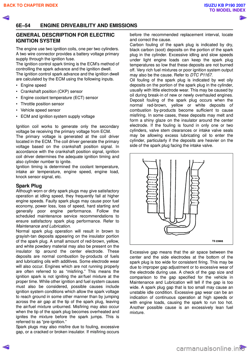
Excessive gap means that the air space between the
center and the side electrodes at the bottom of the
spark plug is too wide for consistent firing. This may be
due to improper gap adjustment or to excessive wear of
the electrode during use. A check of the gap size and
comparison to the gap specified for the vehicle in
Maintenance and Lubrication will tell if the gap is too
wide. A spark plug gap that is too small may cause an
unstable idle condition. Excessive gap wear can be an
indication of continuous operation at high speeds or
with engine loads, causing the spark to run too hot.
Another possible cause is an excessively lean fuel
mixture.
BACK TO CHAPTER INDEX
TO MODEL INDEX
ISUZU KB P190 2007
Page 2235 of 6020
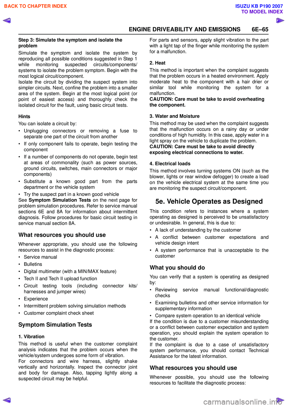
ENGINE DRIVEABILITY AND EMISSIONS 6E–65
Step 3: Simulate the symptom and isolate the
problem
Simulate the symptom and isolate the system by
reproducing all possible conditions suggested in Step 1
while monitoring suspected circuits/components/
systems to isolate the problem symptom. Begin with the
most logical circuit/component.
Isolate the circuit by dividing the suspect system into
simpler circuits. Next, confine the problem into a smaller
area of the system. Begin at the most logical point (or
point of easiest access) and thoroughly check the
isolated circuit for the fault, using basic circuit tests.
Hints
You can isolate a circuit by:
• Unplugging connectors or removing a fuse to separate one part of the circuit from another
• If only component fails to operate, begin testing the component
• If a number of components do not operate, begin test at areas of commonality (such as power sources,
ground circuits, switches, main connectors or major
components)
• Substitute a known good part from the parts department or the vehicle system
• Try the suspect part in a known good vehicle
See Symptom Simulation Tests on the next page for
problem simulation procedures. Refer to service manual
sections 6E and 8A for information about intermittent
diagnosis. Follow procedures for basic circuit testing in
service manual section 8A.
What resources you should use
Whenever appropriate, you should use the following
resources to assist in the diagnostic process:
• Service manual
• Bulletins
• Digital multimeter (with a MIN/MAX feature)
• Tech II and Tech II upload function
• Circuit testing tools (including connector kits/ harnesses and jumper wires)
• Experience
• Intermittent problem solving simulation methods
• Customer complaint check sheet
Symptom Simulation Tests
1. Vibration
This method is useful when the customer complaint
analysis indicates that the problem occurs when the
vehicle/system undergoes some form of vibration.
For connectors and wire harness, slightly shake
vertically and horizontally. Inspect the connector joint
and body for damage. Also, tapping lightly along a
suspected circuit may be helpful. For parts and sensors, apply slight vibration to the part
with a light tap of the finger while monitoring the system
for a malfunction.
2. Heat
This method is important when the complaint suggests
that the problem occurs in a heated environment. Apply
moderate heat to the component with a hair drier or
similar tool while monitoring the system for a
malfunction.
CAUTION: Care must be take to avoid overheating
the component.
3. Water and Moisture
This method may be used when the complaint suggests
that the malfunction occurs on a rainy day or under
conditions of high humidity. In this case, apply water in a
light spray on the vehicle to duplicate the problem.
CAUTION: Care must be take to avoid directly
exposing electrical connections to water.
4. Electrical loads
This method involves turning systems ON (such as the
blower, lights or rear window defogger) to create a load
on the vehicle electrical system at the same time you
are monitoring the suspect circuit/component.
5e. Vehicle Operates as Designed
This condition refers to instances where a system
operating as designed is perceived to be unsatisfactory
or undesirable. In general, this is due to:
• A lack of understanding by the customer
• A conflict between customer expectations and vehicle design intent
• A system performance that is unacceptable to the customer
What you should do
You can verify that a system is operating as designed
by:
• Reviewing service manual functional/diagnostic checks
• Examining bulletins and other service information for supplementary information
• Compare system operation to an identical vehicle
If the condition is due to a customer misunderstanding
or a conflict between customer expectation and system
operation, you should explain the system operation to
the customer.
If the complaint is due to a case of unsatisfactory
system performance, you should contact Technical
Assistance for the latest information.
What resources you should use
Whenever possible, you should use the following
resources to facilitate the diagnostic process:
BACK TO CHAPTER INDEX
TO MODEL INDEX
ISUZU KB P190 2007