key ISUZU KB P190 2007 Workshop User Guide
[x] Cancel search | Manufacturer: ISUZU, Model Year: 2007, Model line: KB P190, Model: ISUZU KB P190 2007Pages: 6020, PDF Size: 70.23 MB
Page 1067 of 6020
Engine Control System (4JH1) 6E-33
Diagnostic System Check - Engine
Controls
Description
The Diagnostic System Check-Engine Controls is an
organized approach to identifying a condition that is
created by a malfunction in the electronic engine control
system. The Diagnostic System Check must be the
starting point for any driveability concern. The
Diagnostic System Check directs the service technician
to the next logical step in order to diagnose the concern.
Understanding and correctly using the diagnostic table
reduces diagnostic time, and prevents the replacement
of good parts.
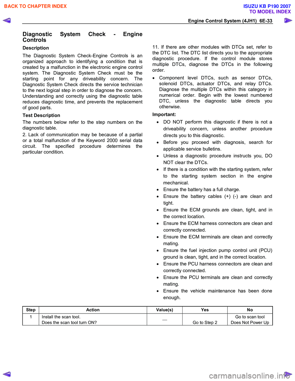
Test Description
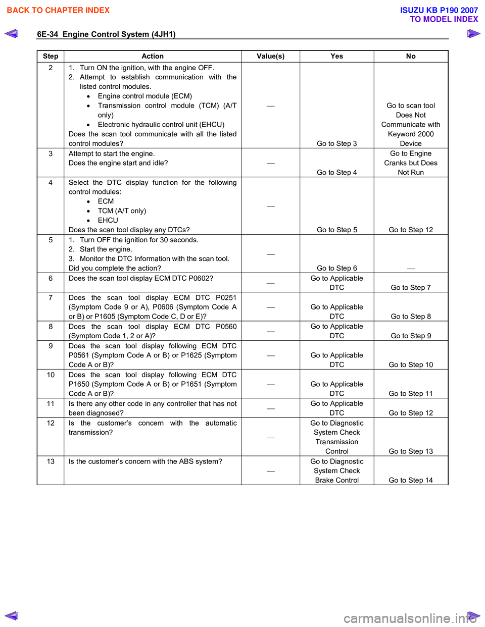
The numbers below refer to the step numbers on the
diagnostic table.
2. Lack of communication may be because of a partial
or a total malfunction of the Keyword 2000 serial data
circuit. The specified procedure determines the
particular condition.
11. If there are other modules with DTCs set, refer to
the DTC list. The DTC list directs you to the appropriate
diagnostic procedure. If the control module stores
multiple DTCs, diagnose the DTCs in the following
order.
• Component level DTCs, such as sensor DTCs,
solenoid DTCs, actuator DTCs, and relay DTCs.
Diagnose the multiple DTCs within this category in
numerical order. Begin with the lowest numbered
DTC, unless the diagnostic table directs you
otherwise.
Important:
• DO NOT perform this diagnostic if there is not a
driveability concern, unless another procedure
directs you to this diagnostic.
• Before you proceed with diagnosis, search fo
r
applicable service bulletins.
• Unless a diagnostic procedure instructs you, DO
NOT clear the DTCs.
• If there is a condition with the starting system, refe
r
to the starting system section in the engine
mechanical.
• Ensure the battery has a full charge.
• Ensure the battery cables (+) (-) are clean and
tight.
• Ensure the ECM grounds are clean, tight, and in
the correct location.
• Ensure the ECM harness connectors are clean and
correctly connected.
• Ensure the ECM terminals are clean and correctl
y
mating.
• Ensure the fuel injection pump control unit (PCU)
ground is clean, tight, and in the correct location.
• Ensure the PCU harness connectors are clean and
correctly connected.
• Ensure the PCU terminals are clean and correctl
y
mating.
• Ensure the vehicle maintenance has been done
enough.
Step Action Value(s) Yes No
1 Install the scan tool.
Does the scan tool turn ON?
Go to Step 2 Go to scan tool
Does Not Power Up
BACK TO CHAPTER INDEX
TO MODEL INDEX
ISUZU KB P190 2007
Page 1068 of 6020
6E-34 Engine Control System (4JH1)
Step Action Value(s) Yes No
2 1. Turn ON the ignition, with the engine OFF.
2. Attempt to establish communication with the listed control modules. • Engine control module (ECM)
• Transmission control module (TCM) (A/T
only)
• Electronic hydraulic control unit (EHCU)
Does the scan tool communicate with all the listed
control modules?
Go to Step 3 Go to scan tool
Does Not
Communicate with Keyword 2000 Device
3 Attempt to start the engine. Does the engine start and idle?
Go to Step 4 Go to Engine
Cranks but Does Not Run
4 Select the DTC display function for the following control modules: • ECM
• TCM (A/T only)
• EHCU
Does the scan tool display any DTCs?
Go to Step 5 Go to Step 12
5 1. Turn OFF the ignition for 30 seconds. 2. Start the engine.
3. Monitor the DTC Information with the scan tool.
Did you complete the action?
Go to Step 6
6 Does the scan tool display ECM DTC P0602?
Go to Applicable
DTC Go to Step 7
7 Does the scan tool display ECM DTC P0251 (Symptom Code 9 or A), P0606 (Symptom Code A
or B) or P1605 (Symptom Code C, D or E)?
Go to Applicable
DTC Go to Step 8
8 Does the scan tool display ECM DTC P0560 (Symptom Code 1, 2 or A)?
Go to Applicable
DTC Go to Step 9
9 Does the scan tool display following ECM DTC
P0561 (Symptom Code A or B) or P1625 (Symptom
Code A or B)?
Go to Applicable
DTC Go to Step 10
10 Does the scan tool display following ECM DTC P1650 (Symptom Code A or B) or P1651 (Symptom
Code A or B)?
Go to Applicable
DTC Go to Step 11
11 Is there any other code in any controller that has not
been diagnosed?
Go to Applicable
DTC Go to Step 12
12 Is the customer’s concern with the automatic
transmission? Go to Diagnostic
System Check Transmission Control Go to Step 13
13 Is the customer’s concern with the ABS system?
Go to Diagnostic
System Check Brake Control Go to Step 14
BACK TO CHAPTER INDEX
TO MODEL INDEX
ISUZU KB P190 2007
Page 1076 of 6020

6E-42 Engine Control System (4JH1)
Scan Tool Does Not Communicate with Keyword 2000 Device
Circuit Description
The engine control module (ECM), transmission control
module (TCM) and anti-theft (keyless entry) control unit
(ACU) all communicate with the scan tool over the
Keyword 2000 serial data link. However, the ECM and
fuel injection pump control unit (PCU) communicates
with each other over the controller area network (CAN)
link. The CAN link is not used for communication with
the scan tool and is shared only between the ECM and
PCU.
Diagnostic Aids
The following conditions will cause a loss of Keyword
2000 serial data communication between the TCM and
EHCU or between the scan tool and any control module:
• A Keyword 2000 serial data circuit open.
• A Keyword 2000 serial data circuit shorted to
ground.
• A Keyword 2000 serial data circuit shorted to
voltage.
•
An internal condition within a module or connector
on the Keyword 2000 serial data circuit, that causes
a short to voltage or ground to the Keyword 2000
serial data circuit.
• Open ground circuit (pin 5) at the DLC.
Scan tool Does Not Communicate with Keyword
2000 Device
Schematic Reference: Engine Controls Schematics
Connector End View Reference: Engine Controls
Connector End Views or Engine Control Module (ECM)
Connector End Views
Step Action Value(s) Yes No
1 Did you perform the Diagnostic System Check-
Engine Controls?
Go to Step 2 Go to Diagnostic
System Check-
Engine Controls
2 1. Install the scan tool. 2. Turn ON the ignition, with the engine OFF.
3. Attempt to communicate with the listed control modules. • Engine control module (ECM)
• Transmission control module (TCM) (A/T
only)
• Electronic hydraulic control unit (EHCU)
Does the scan tool communicate with all the listed
control modules?
Go to Step 3 Go to Step 8
3 Does the scan tool communicate with the ECM?
Go to Step 4 Go to Lost
Communication with The ECM
4 Does the scan tool communicate with the TCM?
Go to Step 5 Go to Diagnostic
System Check Transmission Control
5 Does the scan tool communicate with the EHCU?
Go to Step 6 Go to Diagnostic
System Brake
6 Test the Keyword 2000 serial data circuit for an intermittently short to ground or intermittently short to
voltage. Then, test the Keyword 2000 serial data
circuit for an intermittently open (based on which
control module did not communicate) at the
connection in the circuit.
Did you find and correct the condition?
Go to Step 15 System OK
7 Test the data link connector (DLC) ground circuit at terminal 5 for an open circuit or poor connection.
Did you find and correct the condition?
Go to Step 15 Go to Step 8
BACK TO CHAPTER INDEX
TO MODEL INDEX
ISUZU KB P190 2007
Page 1077 of 6020

Engine Control System (4JH1) 6E-43
Step Action Value(s) Yes No
8 1. Turn OFF the ignition.
2. Disconnect the ECM C-56 and C-57 harness connectors.
3. Turn ON the ignition, with the engine OFF.
4. Attempt to communicate with the TCM and EHCU.
Does the scan tool communicate with the TCM and
EHCU?
Go to Step 12 Go to Step 9
9 1. Turn OFF the ignition. 2. Reconnect the ECM C-56 and C-57 harness connectors.
3. Disconnect the TCM A and B harness connectors.
4. Turn ON the ignition, with the engine OFF.
5. Attempt to communicate with the ECM and EHCU.
Does the scan tool communicate with the ECM and
EHCU?
Go to Step 13 Go to Step 10
10 1. Turn OFF the ignition. 2. Reconnect the TCM A and B harness connectors.
3. Disconnect the EHCU C-67 harness connectors.
4. Turn ON the ignition, with the engine OFF.
5. Attempt to communicate with the ECM and TCM.
Does the scan tool communicate with the ECM and
TCM?
Go to Step 14 Go to Step 11
11 Repair the short to ground or short to voltage on the Keyword 2000 serial data circuit between the DLC
and ECM, TCM and EHCU.
Did you complete the repair?
Go to Step 15
12 Important: Replacement ECM must be
programmed.
Replace the ECM. Refer to Engine Control Module
(ECM) Replacement in this section.
Did you complete the replacement?
Go to Step 15
13 Important: Replacement TCM must be
programmed.
Replace the TCM. Refer to Transmission Control
Module (TCM) Replacement in the transmission
section.
Did you complete the replacement?
Go to Step 15
14 Replace the EHCU. Refer to Electronic Hydraulic
Control Unit in the anti-lock brake system section.
Did you complete the replacement?
Go to Step 15
15 Attempt to communicate with the ECM, TCM and
EHCU.
Does the scan tool communicate with the ECM, TCM
and EHCU?
System OK Go to Step 2
BACK TO CHAPTER INDEX
TO MODEL INDEX
ISUZU KB P190 2007
Page 1078 of 6020

6E-44 Engine Control System (4JH1)
Lost Communication with The Engine Control Module (ECM)
Circuit Description
The engine control module (ECM), transmission control
module (TCM) and electronic hydraulic control unit
(EHCU) all communicate with the scan tool over the
Keyword 2000 serial data link. However, the ECM and
fuel injection pump control unit (PCU) communicates
with each other over the controller area network (CAN)
link. The CAN link is not used for communication with
the scan tool and is shared only between the ECM and
PCU.
Lost Communication with The Engine Control
Module (ECM)
Schematic Reference: Engine Controls Schematics
Connector End View Reference: Engine Controls
Connector End Views or Engine Control Module (ECM)
Connector End Views
Step Action Value(s) Yes No
1 Did you perform the Diagnostic System Check-
Engine Controls?
Go to Step 2 Go to Diagnostic
System Check-
Engine Controls
2 Attempt to establish engine control module (ECM) communications with the scan tool.
Does the ECM communicate with the scan tool?
Go to Intermittent
Conditions Go to Step 3
3 Check the ECM C-56 and C-57 connectors for poor connections.
Did you find and correct the condition?
Go to Step 17 Go to Step 4
4 Check the electronic hydraulic control unit (EHCU)
C-67 connector for poor connection.
Did you find and correct the condition?
Go to Step 17 Go to Step 5
5 1. Turn ON the ignition, with the engine OFF. 2. Check the ECM (30A) (SFB-4), ECM (10A) fuse (EB-4) and Engine (15A) fuse (C-6).Replace and
retest if open. If any fuse continues to open,
check for a short to ground on each circuit fed by
that fuse.
3. Turn OFF the ignition.
4. Disconnect the ECM C-56 harness connector.
5. Turn ON the ignition, with the engine OFF.
6. Connect a test lamp to ground and check for voltage at the ignition voltage supply circuit at the
ECM (pin 39 of C-56 connector).
Does the test lamp illuminate?
Go to Step 6 Go to Step 14
6 1. Turn OFF the ignition. 2. Connect a DMM between the Keyword 2000 serial data circuit at the ECM (pin 35 of C-56
connector) and the EHCU (pin 11 of C-67
connector).
3. Test the circuits for an open circuit or high resistance.
4. Repair the circuit(s) as necessary.
Did you find and correct the condition?
Go to Step 17 Go to Step 7
7 1. Turn OFF the ignition. 2. Connect a DMM between the Keyword 2000 serial data circuit at the EHCU (pin 11 of C-67
connector) and the DLC (pin 7 of B-58
connector).
3. Test the circuits for an open circuit or high resistance.
4. Repair the circuit(s) as necessary.
Did you find and correct the condition?
Go to Step 17 Go to Step 8
BACK TO CHAPTER INDEX
TO MODEL INDEX
ISUZU KB P190 2007
Page 1081 of 6020
Engine Control System (4JH1) 6E-47
Engine Cranks but Does Not Run
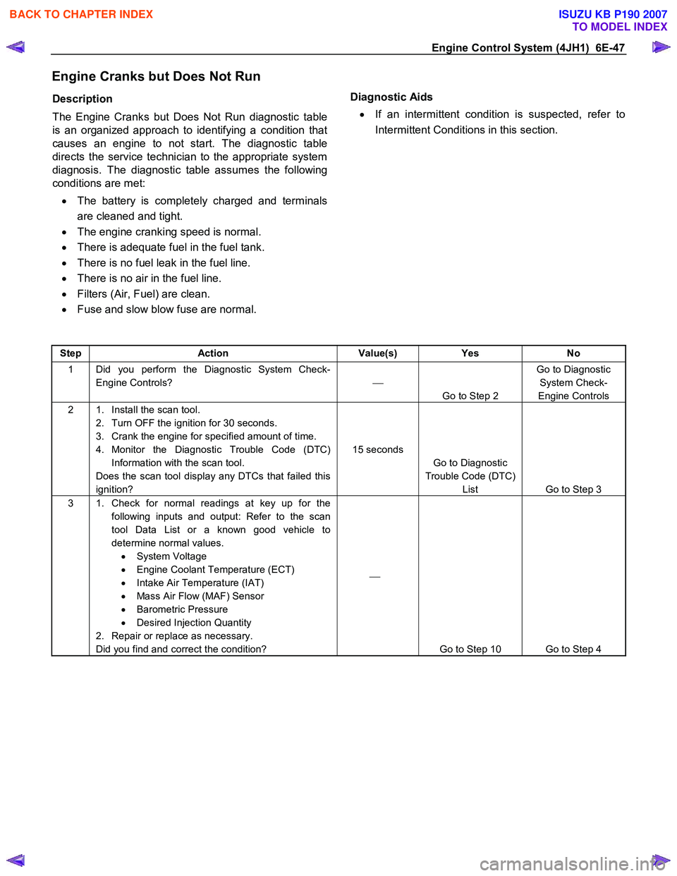
Description
The Engine Cranks but Does Not Run diagnostic table
is an organized approach to identifying a condition that
causes an engine to not start. The diagnostic table
directs the service technician to the appropriate system
diagnosis. The diagnostic table assumes the following
conditions are met:
• The battery is completely charged and terminals
are cleaned and tight.
• The engine cranking speed is normal.
• There is adequate fuel in the fuel tank.
• There is no fuel leak in the fuel line.
• There is no air in the fuel line.
• Filters (Air, Fuel) are clean.
• Fuse and slow blow fuse are normal.
Diagnostic Aids
• If an intermittent condition is suspected, refer to
Intermittent Conditions in this section.
Step Action Value(s) Yes No
1 Did you perform the Diagnostic System Check-
Engine Controls?
Go to Step 2 Go to Diagnostic
System Check-
Engine Controls
2 1. Install the scan tool. 2. Turn OFF the ignition for 30 seconds.
3. Crank the engine for specified amount of time.
4. Monitor the Diagnostic Trouble Code (DTC) Information with the scan tool.
Does the scan tool display any DTCs that failed this
ignition? 15 seconds
Go to Diagnostic
Trouble Code (DTC) List Go to Step 3
3 1. Check for normal readings at key up for the
following inputs and output: Refer to the scan
tool Data List or a known good vehicle to
determine normal values. • System Voltage
• Engine Coolant Temperature (ECT)
• Intake Air Temperature (IAT)
• Mass Air Flow (MAF) Sensor
• Barometric Pressure
• Desired Injection Quantity
2. Repair or replace as necessary.
Did you find and correct the condition?
Go to Step 10 Go to Step 4
BACK TO CHAPTER INDEX
TO MODEL INDEX
ISUZU KB P190 2007
Page 1096 of 6020
6E-62 Engine Control System (4JH1)
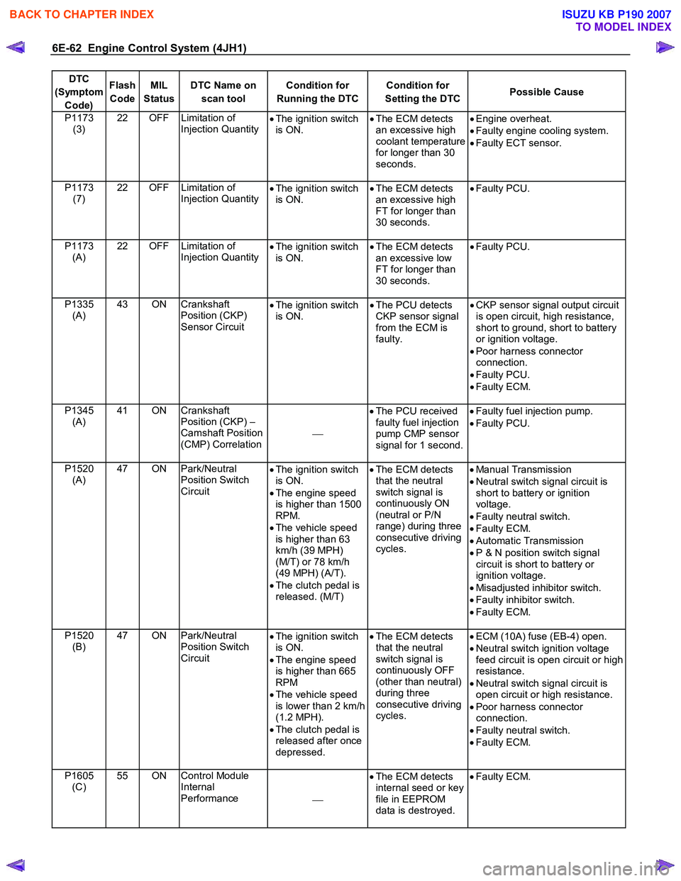
DTC
(Symptom Code) Flash
Code MIL
Status DTC Name on
scan tool Condition for
Running the DTC Condition for
Setting the DTC Possible Cause
P1173
(3) 22 OFF Limitation of
Injection Quantity •
The ignition switch
is ON. •
The ECM detects
an excessive high
coolant temperature
for longer than 30
seconds.
•
Engine overheat.
• Faulty engine cooling system.
• Faulty ECT sensor.
P1173 (7) 22 OFF Limitation of
Injection Quantity
•
The ignition switch
is ON. •
The ECM detects
an excessive high
FT for longer than
30 seconds.
•
Faulty PCU.
P1173 (A) 22 OFF Limitation of
Injection Quantity
•
The ignition switch
is ON. •
The ECM detects
an excessive low
FT for longer than
30 seconds.
•
Faulty PCU.
P1335 (A) 43 ON Crankshaft
Position (CKP)
Sensor Circuit •
The ignition switch
is ON. •
The PCU detects
CKP sensor signal
from the ECM is
faulty.
•
CKP sensor signal output circuit
is open circuit, high resistance,
short to ground, short to battery
or ignition voltage.
• Poor harness connector
connection.
• Faulty PCU.
• Faulty ECM.
P1345 (A) 41 ON Crankshaft
Position (CKP) –
Camshaft Position
(CMP) Correlation
•
The PCU received
faulty fuel injection
pump CMP sensor
signal for 1 second.
•
Faulty fuel injection pump.
• Faulty PCU.
P1520 (A) 47 ON Park/Neutral
Position Switch
Circuit •
The ignition switch
is ON.
• The engine speed
is higher than 1500
RPM.
• The vehicle speed
is higher than 63
km/h (39 MPH)
(M/T) or 78 km/h
(49 MPH) (A/T).
• The clutch pedal is
released. (M/T)
•
The ECM detects
that the neutral
switch signal is
continuously ON
(neutral or P/N
range) during three
consecutive driving
cycles.
•
Manual Transmission
• Neutral switch signal circuit is
short to battery or ignition
voltage.
• Faulty neutral switch.
• Faulty ECM.
• Automatic Transmission
• P & N position switch signal
circuit is short to battery or
ignition voltage.
• Misadjusted inhibitor switch.
• Faulty inhibitor switch.
• Faulty ECM.
P1520 (B) 47 ON Park/Neutral
Position Switch
Circuit •
The ignition switch
is ON.
• The engine speed
is higher than 665
RPM
• The vehicle speed
is lower than 2 km/h
(1.2 MPH).
• The clutch pedal is
released after once
depressed.
•
The ECM detects
that the neutral
switch signal is
continuously OFF
(other than neutral)
during three
consecutive driving
cycles.
•
ECM (10A) fuse (EB-4) open.
• Neutral switch ignition voltage
feed circuit is open circuit or high
resistance.
• Neutral switch signal circuit is
open circuit or high resistance.
• Poor harness connector
connection.
• Faulty neutral switch.
• Faulty ECM.
P1605 (C) 55 ON Control Module
Internal
Performance •
The ECM detects
internal seed or key
file in EEPROM
data is destroyed.
•
Faulty ECM.
BACK TO CHAPTER INDEX
TO MODEL INDEX
ISUZU KB P190 2007
Page 1097 of 6020
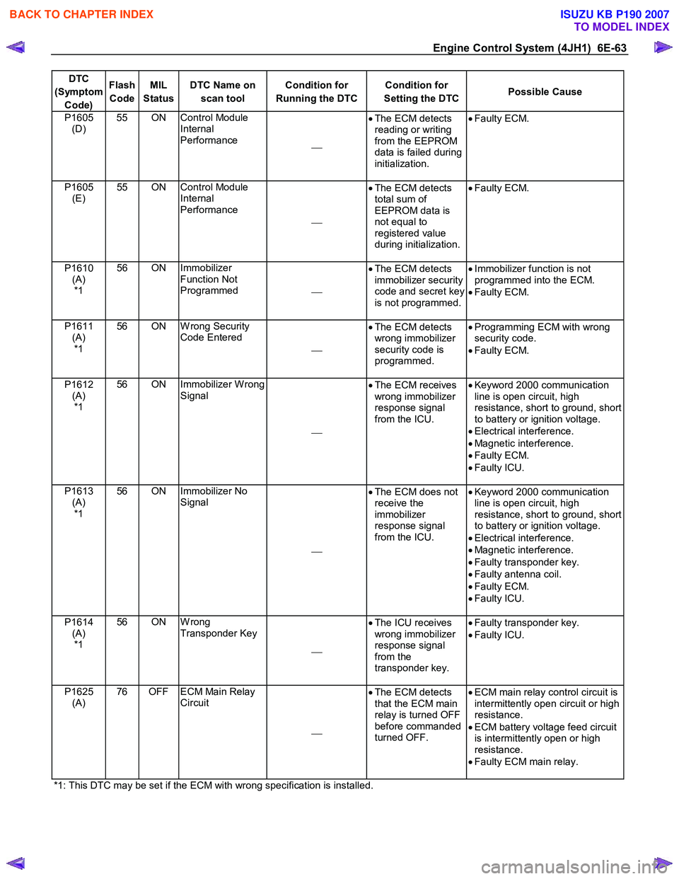
Engine Control System (4JH1) 6E-63
DTC
(Symptom Code) Flash
Code MIL
Status DTC Name on
scan tool Condition for
Running the DTC Condition for
Setting the DTC Possible Cause
P1605
(D) 55 ON Control Module
Internal
Performance •
The ECM detects
reading or writing
from the EEPROM
data is failed during
initialization.
•
Faulty ECM.
P1605
(E) 55 ON Control Module
Internal
Performance
•
The ECM detects
total sum of
EEPROM data is
not equal to
registered value
during initialization.
•
Faulty ECM.
P1610
(A) *1 56 ON Immobilizer
Function Not
Programmed •
The ECM detects
immobilizer security
code and secret key
is not programmed.
•
Immobilizer function is not
programmed into the ECM.
• Faulty ECM.
P1611 (A) *1 56 ON W rong Security
Code Entered
•
The ECM detects
wrong immobilizer
security code is
programmed.
•
Programming ECM with wrong
security code.
• Faulty ECM.
P1612 (A) *1 56 ON Immobilizer W rong
Signal
•
The ECM receives
wrong immobilizer
response signal
from the ICU.
•
Keyword 2000 communication
line is open circuit, high
resistance, short to ground, short
to battery or ignition voltage.
• Electrical interference.
• Magnetic interference.
• Faulty ECM.
• Faulty ICU.
P1613 (A) *1 56 ON Immobilizer No
Signal
•
The ECM does not
receive the
immobilizer
response signal
from the ICU.
•
Keyword 2000 communication
line is open circuit, high
resistance, short to ground, short
to battery or ignition voltage.
• Electrical interference.
• Magnetic interference.
• Faulty transponder key.
• Faulty antenna coil.
• Faulty ECM.
• Faulty ICU.
P1614 (A) *1 56 ON W rong
Transponder Key
•
The ICU receives
wrong immobilizer
response signal
from the
transponder key.
•
Faulty transponder key.
• Faulty ICU.
P1625 (A) 76 OFF ECM Main Relay
Circuit
•
The ECM detects
that the ECM main
relay is turned OFF
before commanded
turned OFF.
•
ECM main relay control circuit is
intermittently open circuit or high
resistance.
• ECM battery voltage feed circuit
is intermittently open or high
resistance.
• Faulty ECM main relay.
*1: This DTC may be set if the ECM with wrong specification is installed.
BACK TO CHAPTER INDEX
TO MODEL INDEX
ISUZU KB P190 2007
Page 1141 of 6020

Engine Control System (4JH1) 6E-107
DTC P0243 (Symptom Code 3) (Flash Code 64)
Circuit Description
The engine control module (ECM) controls the
turbocharger wastegate valve based on the barometric
pressure in order to reduce turbocharger spinning
speeds at high altitude area. The ECM controls the
turbocharger wastegate valve diaphragm by acting the
regulated vacuum pressure via controlling the solenoid
valve. The vacuum pressure sensor monitors the
regulated vacuum pressure to the turbocharge
r
wastegate valve. The ECM calculates desired vacuum
pressure and it compares the calculated desired
vacuum pressure to the actual value to determine the
solenoid valve position. W hen the actual vacuum
pressure is higher than the desired value, the solenoid
valve is closed to decrease the vacuum pressure. An
expected vacuum pressure amount should be detected
while the engine running. If the ECM detects the actual
vacuum pressure amount is higher than desired
vacuum pressure amount, this DTC will set.
Condition for Running the DTC
• The ignition switch is ON.
• The barometric pressure (BARO) is between 0
hPa and 3500 hPa.
• The intake air temperature (IAT) is between -50°C
(-58 °F) and 200°C (392°F).
• The engine coolant temperature (ECT) is between
-50°C (-58 °F) and 150°C (302°F)
Condition for Setting the DTC
• The ECM detects that the vacuum pressure is 50
hPa higher than the desired vacuum pressure for
3 seconds. This indicates excessive high vacuum
pressure.
Action Taken When the DTC Sets
• The ECM illuminates the malfunction indicato
r
lamp (MIL) when the diagnostic runs and fails.
• The ECM limits fuel injection quantity.
• The ECM uses an EGR solenoid valve control
substitution of 10%.
Condition for Clearing the MIL/DTC
• The ECM turns OFF the MIL when the diagnostic
runs and does not fail.
• A history DTC clears after 40 consecutive driving
cycles without a fault. Or clear with the scan tool.
Diagnostic Aids
• If an intermittent condition is suspected, refer to
Intermittent Conditions in this section.
• Misrouted vacuum hoses will cause this DTC to
set.
Test Description
The numbers below refer to the step number on the
diagnostic table.
4. A skewed vacuum pressure sensor value (shifted to
a high pressure) can set this DTC. The Vacuum
Pressure on the scan tool should read near doubled
barometric pressure (BARO) with the key ON and
engine OFF.
5. A skewed BARO sensor value (shifted to a lowe
r
pressure) may set this DTC. The BARO on the scan
tool should read near surrounding barometric pressure.
DTC P0243 (Symptom Code 3) (Flash Code 64)
Schematic Reference: Engine Controls Schematics
Connector End View Reference: Engine Controls
Connector End Views or Engine Control Module (ECM)
Connector End Views
Step Action Value(s) Yes No
1 Did you perform the Diagnostic System Check-
Engine Controls?
Go to Step 2 Go to Diagnostic
System Check-
Engine Controls
2 1. Install the scan tool. 2. Turn OFF the ignition for 30 seconds.
3. Start the engine and let idle for 30 seconds.
4. Monitor the Diagnostic Trouble Code (DTC) Information with the scan tool.
Is DTC P0105 (Symptom Code 1, 2, 7 or 9) or
P0243 (Symptom Code 4 or 8) set?
Go to Applicable DTC Go to Step 3
BACK TO CHAPTER INDEX
TO MODEL INDEX
ISUZU KB P190 2007
Page 1148 of 6020

6E-114 Engine Control System (4JH1)
DTC P0243 (Symptom Code 5) (Flash Code 64)
Circuit Description
The engine control module (ECM) controls the
turbocharger wastegate valve based on the barometric
pressure in order to reduce turbocharger spinning
speeds at high altitude area. The ECM controls the
turbocharger wastegate valve diaphragm by acting the
regulated vacuum pressure via controlling the solenoid
valve. The vacuum pressure sensor monitors the
regulated vacuum pressure to the turbocharge
r
wastegate valve. The ECM calculates desired vacuum
pressure and it compares the calculated desired
vacuum pressure to the actual value to determine the
solenoid valve position. W hen the actual vacuum
pressure is higher than the desired value, the solenoid
valve is closed to decrease the vacuum pressure. An
expected vacuum pressure amount should be detected
while the engine running. If the ECM detects the actual
vacuum pressure amount is lower than desired vacuum
pressure amount, this DTC will set.
Condition for Running the DTC
• The ignition switch is ON.
• The barometric pressure (BARO) is between 0
hPa and 3500 hPa.
• The intake air temperature (IAT) is between -50°C
(-58 °F) and 200°C (392°F).
• The engine coolant temperature (ECT) is between
-50°C (-58 °F) and 150°C (302°F)
Condition for Setting the DTC
• The ECM detects that the vacuum pressure is 50
hPa lower than the desired vacuum pressure for 3
seconds. This indicates excessive low vacuum
pressure.
Action Taken When the DTC Sets
• The ECM illuminates the malfunction indicato
r
lamp (MIL) when the diagnostic runs and fails.
• The ECM limits fuel injection quantity.
• The ECM uses an EGR solenoid valve control
substitution of 10%.
Condition for Clearing the MIL/DTC
• The ECM turns OFF the MIL when the diagnostic
runs and does not fail.
• A history DTC clears after 40 consecutive driving
cycles without a fault. Or clear with the scan tool.
Diagnostic Aids
• If an intermittent condition is suspected, refer to
Intermittent Conditions in this section.
• Misrouted vacuum hoses may set this DTC.
• A vacuum pump problem will cause this DTC.
Test Description
The numbers below refer to the step number on the
diagnostic table.
4. A skewed vacuum pressure sensor value (shifted to
a low pressure) can set this DTC. The Vacuum
Pressure on the scan tool should read near doubled
barometric pressure (BARO) with the key ON and
engine OFF.
5. A skewed BARO sensor value (shifted to a highe
r
pressure) may set this DTC. The BARO on the scan
tool should read near surrounding barometric pressure.
DTC P0243 (Symptom Code 5) (Flash Code 64)
Schematic Reference: Engine Controls Schematics
Connector End View Reference: Engine Controls
Connector End Views or Engine Control Module (ECM)
Connector End Views
Step Action Value(s) Yes No
1 Did you perform the Diagnostic System Check-
Engine Controls?
Go to Step 2 Go to Diagnostic
System Check-
Engine Controls
2 1. Install the scan tool. 2. Turn OFF the ignition for 30 seconds.
3. Start the engine and let idle for 30 seconds.
4. Monitor the Diagnostic Trouble Code (DTC) Information with the scan tool.
Is DTC P0105 (Symptom Code 1, 2, 7 or 9) or
P0243 (Symptom Code 4 or 8) set?
Go to Applicable DTC Go to Step 3
BACK TO CHAPTER INDEX
TO MODEL INDEX
ISUZU KB P190 2007