FLASH CODE ISUZU KB P190 2007 Workshop Repair Manual
[x] Cancel search | Manufacturer: ISUZU, Model Year: 2007, Model line: KB P190, Model: ISUZU KB P190 2007Pages: 6020, PDF Size: 70.23 MB
Page 4082 of 6020
7A2-116 TRANSMISSION CONTROL SYSTEM (AW30–40LE)
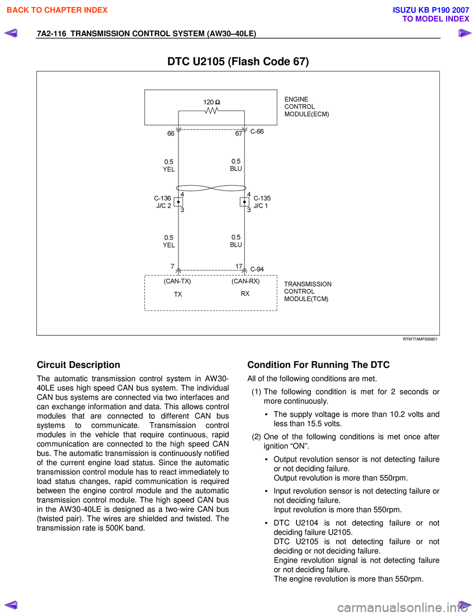
DTC U2105 (Flash Code 67)
RTW 77AMF000801
Circuit Description
The automatic transmission control system in AW 30-
40LE uses high speed CAN bus system. The individual
CAN bus systems are connected via two interfaces and
can exchange information and data. This allows control
modules that are connected to different CAN bus
systems to communicate. Transmission control
modules in the vehicle that require continuous, rapid
communication are connected to the high speed CAN
bus. The automatic transmission is continuously notified
of the current engine load status. Since the automatic
transmission control module has to react immediately to
load status changes, rapid communication is required
between the engine control module and the automatic
transmission control module. The high speed CAN bus
in the AW 30-40LE is designed as a two-wire CAN bus
(twisted pair). The wires are shielded and twisted. The
transmission rate is 500K band.
Condition For Running The DTC
All of the following conditions are met.
(1) The following condition is met for 2 seconds o
r
more continuously.
• The supply voltage is more than 10.2 volts and
less than 15.5 volts.
(2) One of the following conditions is met once afte
r
ignition “ON”.
• Output revolution sensor is not detecting failure
or not deciding failure.
Output revolution is more than 550rpm.
• Input revolution sensor is not detecting failure o
r
not deciding failure.
Input revolution is more than 550rpm.
• DTC U2104 is not detecting failure or not
deciding failure U2105.
DTC U2105 is not detecting failure or not
deciding or not deciding failure.
Engine revolution signal is not detecting failure
or not deciding failure.
The engine revolution is more than 550rpm.
BACK TO CHAPTER INDEX
TO MODEL INDEX
ISUZU KB P190 2007
Page 4285 of 6020
TRANSMISSION CONTROL SYSTEM (JR405E) 7A2-1
TRANSMISSION
TRANSMISSION CONTROL SYSTEM (JR405E)
This manual conforms when Scan Tool of ISO CAN Base Software is used.
TABLE OF CONTENTS
Specifications ...................................................... 7A2-2Transmission General Specifications ............... 7A2-2
Transmission Fluid Temperature vs. Resistance..... 7A2-3
Clutch, Brake, Solenoid and Pressure Switch Logic........ 7A2-4
Diagnostic Trouble Code (DTC) List ................ 7A2-5
Schematic and Routing Diagrams....................... 7A2-6 Transmission Controls Schematics .................. 7A2-6
Component Locator........................................... 7A2-13 Transmission Controls Component Views ..... 7A2-13
Transmission Control Module (TCM) Connector End Views ................................... 7A2-17
Transmission Control Connector End Views.. 7A2-18
Diagnostic Information and Procedures ............ 7A2-21
Diagnostic Starting Point - Transmission Controls......... 7A2-21
Diagnostic System Check - Transmission Controls....... 7A2-22
Scan Tool Data List ........................................ 7A2-24
Scan Tool Data Definitions............................. 7A2-25
Scan Tool Output Controls ............................. 7A2-27
Scan Tool Does Not Power Up ...................... 7A2-28
Scan Tool Does Not Communicate with Keyword Device .................................... 7A2-29
Lost Communication with The Transmission Control Module (TCM)
.... 7A2-31
DTC P0560 (Flash Code 16).......................... 7A2-33
DTC P0602 .................................................... 7A2-35
DTC P0705 (Flash Code 17).......................... 7A2-36
DTC P0710 (Flash Code 15).......................... 7A2-40
DTC P0717 (Flash Code 14).......................... 7A2-44
DTC P0722 (Flash Code 11).......................... 7A2-47
DTC P0727 (Flash Code 13).......................... 7A2-50
DTC P0731, P0732, P0733 or P0734 (Flash Code 41, 42, 43 or 44)....................... 7A2-52
DTC P0748 (Flash Code 35).......................... 7A2-55
DTC P0753 (Flash Code 31).......................... 7A2-58
DTC P0758 (Flash Code 32).......................... 7A2-61
DTC P0763 (Flash Code 33).......................... 7A2-64
DTC P0768 (Flash Code 34).......................... 7A2-67
DTC P1120 (Flash Code 22).......................... 7A2-70
DTC P1750 (Flash Code 51).......................... 7A2-71
DTC P1755 (Flash Code 52).......................... 7A2-73
DTC P1853 (Flash Code 26).......................... 7A2-75
DTC P1858 (Flash Code 27).......................... 7A2-78
DTC P1860 (Flash Code 36).......................... 7A2-81
DTC P1863 (Flash Code 28).......................... 7A2-84
DTC P1875 (Flash Code 25).......................... 7A2-87
Check Trans Lamp Inoperative, Always On or Always Blinking ...................... 7A2-89
Symptoms - Transmission Controls .................. 7A2-92 Symptoms - Transmission Controls ............... 7A2-92
Intermittent Conditions ................................... 7A2-93 Vehicle Does Not Run .................................... 7A2-95
Trouble at Starting.......................................... 7A2-95
Faulty Gearshift .............................................. 7A2-95
Faulty Shift Pattern......................................... 7A2-95
No or Error Gearshift ...................................... 7A2-95
Faulty Operation During Running................... 7A2-95
Faulty Operation in Stopping.......................... 7A2-95
Faulty Lock Up ............................................... 7A2-95
No Lock Up .................................................... 7A2-95
Transmission Fluid Leak ................................ 7A2-95
Others ............................................................ 7A2-95
Test Instructions .............................................. 7A2-121 Line Pressure Test ....................................... 7A2-121
Stall Test ...................................................... 7A2-123
Time Lag Test .............................................. 7A2-124
Road Test..................................................... 7A2-125
TCM Signal Test .......................................... 7A2-134
Repair Instructions .......................................... 7A2-139
Transmission Controls Module (TCM) Replacement.... 7A2-139
Service Programming System (SPS) Description........ 7A2-139
Service Programming System (SPS) (Remote Procedure)......................... 7A2-140
Service Programming System (SPS) (Pass-Thru Procedure)..................... 7A2-141
Description and Operation .............................. 7A2-143 Transmission Identification Information........ 7A2-143
Transmission General Description ............... 7A2-143
Transmission Component Description ......... 7A2-144
Transmission Control System Description ... 7A2-152
Transmission Power Flow Description ......... 7A2-161
Special Tools and Equipment ......................... 7A2-170 Special Tools and Equipment ...................... 7A2-170
BACK TO CHAPTER INDEX
TO MODEL INDEX
ISUZU KB P190 2007
Page 4289 of 6020

TRANSMISSION CONTROL SYSTEM (JR405E) 7A2-5
Diagnostic Trouble Code (DTC) List
DTC Flash CodeDTC Descriptor
P0560 16 System Voltage Malfunction
P0602 — Control Module Programming Error
P0705 17 Inhibitor Switch Malfunction
P0710 15 Transmission Fluid Temperature Sensor Circuit Malfunction
P0717 14 Input/Turbine Speed Sensor “A” Circuit No Signal
P0722 11 Output Speed Sensor Circuit No Signal
P0727 13 Engine Speed Sensor Input Circuit No Signal
P0731 41 Gear 1 Incorrect Ratio
P0732 42 Gear 2 Incorrect Ratio
P0733 43 Gear 3 Incorrect Ratio
P0734 44 Gear 4 Incorrect Ratio
P0748 35 Line Pressure Solenoid Malfunction
P0753 31 Low & Reverse Brake Duty Solenoid Malfunction
P0758 32 2-4 Brake Duty Solenoid Malfunction
P0763 33 High Clutch Duty Solenoid Malfunction
P0768 34 Low Clutch Duty Solenoid Malfunction
P1120 22 Throttle Position Signal Malfunction
P1750 51 Low & Reverse Brake Fail Safe Valve Malfunction
P1755 52 2-4 Brake Fail Safe Valve Malfunction
P1853 26 Low & Reverse Brake Pressure Switch Malfunction
P1858 27 2-4 Brake Pressure Switch Malfunction
P1860 36 Lock Up Duty Solenoid Malfunction
P1863 28 High Clutch Pressure Switch Malfunction
P1875 25 Ground Return Malfunction
BACK TO CHAPTER INDEX
TO MODEL INDEX
ISUZU KB P190 2007
Page 4305 of 6020
TRANSMISSION CONTROL SYSTEM (JR405E) 7A2-21
Diagnostic Information and Procedures
Diagnostic Starting Point - Transmission Controls
Begin the system diagnosis with Diagnostic System
Check - Transmission Controls. The Diagnostic System
Check - Transmission Controls will provide the
following information:
• The identification of the control modules which command the system.
• The ability of the control modules to communicate through the serial data circuit.
• The identification of any stored diagnostic trouble codes (DTCs) and the their statuses.
The use of the Diagnostic System Check -
Transmission Controls will identify the correct
procedure for diagnosing the system and where the
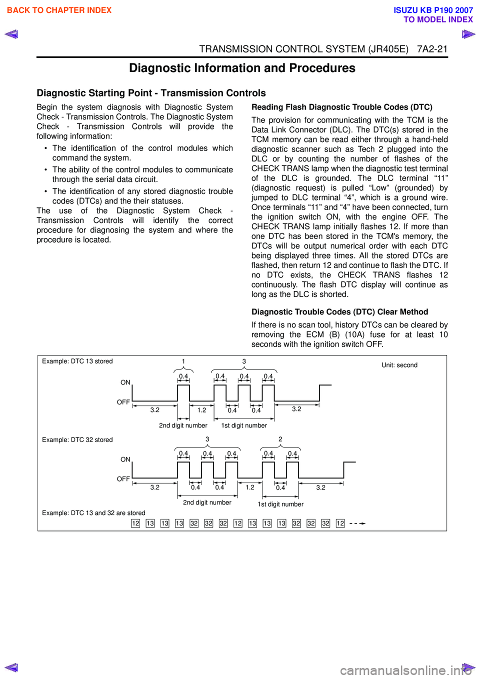
procedure is located. Reading Flash Diagnostic Trouble Codes (DTC)
The provision for communicating with the TCM is the
Data Link Connector (DLC). The DTC(s) stored in the
TCM memory can be read either through a hand-held
diagnostic scanner such as Tech 2 plugged into the
DLC or by counting the number of flashes of the
CHECK TRANS lamp when the diagnostic test terminal
of the DLC is grounded. The DLC terminal “11”
(diagnostic request) is pulled “Low” (grounded) by
jumped to DLC terminal “4”, which is a ground wire.
Once terminals “11” and “4” have been connected, turn
the ignition switch ON, with the engine OFF. The
CHECK TRANS lamp initially flashes 12. If more than
one DTC has been stored in the TCM's memory, the
DTCs will be output numerical order with each DTC
being displayed three times. All the stored DTCs are
flashed, then return 12 and continue to flash the DTC. If
no DTC exists, the CHECK TRANS flashes 12
continuously. The flash DTC display will continue as
long as the DLC is shorted.
Diagnostic Trouble Codes (DTC) Clear Method
If there is no scan tool, history DTCs can be cleared by
removing the ECM (B) (10A) fuse for at least 10
seconds with the ignition switch OFF.
Unit: second
131313323232121313133232321212
Example: DTC 13 stored
ON
OFF
Example: DTC 32 stored
Example: DTC 13 and 32 are stored
ON
OFF 3
1
0.40.40.40.4
32
0.40.40.40.40.4
2nd digit number1st digit number
3.23.20.40.40.41.2
2nd digit number 1st digit number
0.40.41.23.23.2
BACK TO CHAPTER INDEX
TO MODEL INDEX
ISUZU KB P190 2007
Page 4311 of 6020
TRANSMISSION CONTROL SYSTEM (JR405E) 7A2-27
Power Drive Switch
This parameter displays the input state of the power
drive switch to the TCM. When the switch is pressed,
the scan tool displays On.
Power Drive Lamp
This parameter displays the commanded state of the
power drive lamp control circuit. The lamp should be
On when the scan tool indicates command On.
Brake Pedal Switch
This parameter displays the input state of the brake
pedal switch to the TCM. When the pedal is depressed,
scan tool displays On. Diagnostic Switch
This parameter displays the input state of the
diagnostic request switch to the TCM. When the data
link connector (DLC) terminal 11 is pulled low, the
check trans lamp blinks to indicate flash code.
Check Trans Lamp
This parameter displays the commanded state of the
check trans lamp control circuit. The lamp should be
On when the scan tool indicates command On.
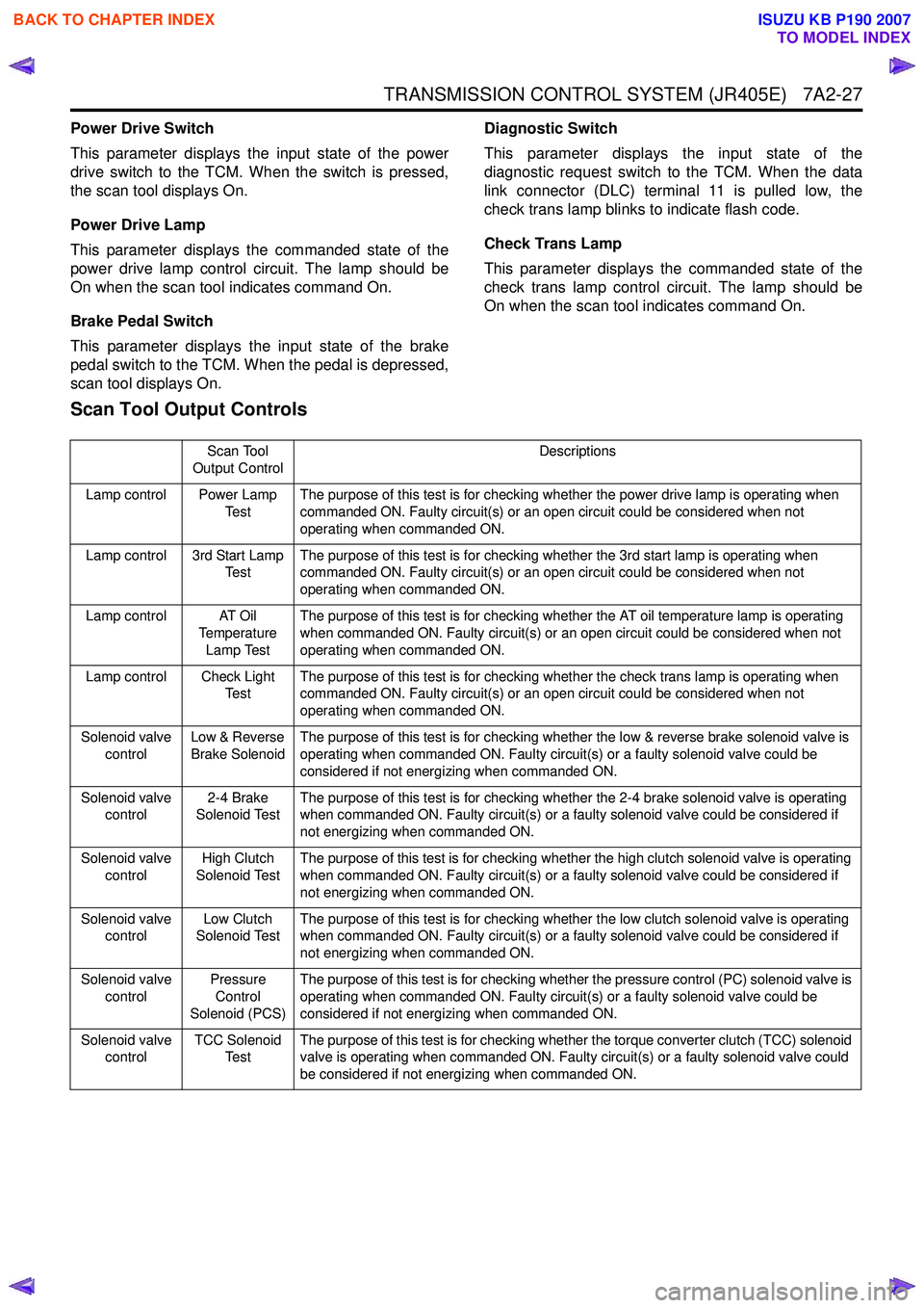
Scan Tool Output Controls
Scan Tool
Output Control Descriptions
Lamp control Power Lamp Te s tThe purpose of this test is for checking whether the power drive lamp is operating when
commanded ON. Faulty circuit(s) or an open circuit could be considered when not
operating when commanded ON.
Lamp control 3rd Start Lamp Te s t The purpose of this test is for checking whether the 3rd start lamp is operating when
commanded ON. Faulty circuit(s) or an open circuit could be considered when not
operating when commanded ON.
Lamp control AT Oil Temperature
Lamp Test The purpose of this test is for checking whether the AT oil temperature lamp is operating
when commanded ON. Faulty circuit(s) or an open circuit could be considered when not
operating when commanded ON.
Lamp control Check Light Te s t The purpose of this test is for checking whether the check trans lamp is operating when
commanded ON. Faulty circuit(s) or an open circuit could be considered when not
operating when commanded ON.
Solenoid valve control Low & Reverse
Brake Solenoid The purpose of this test is for checking whether the low & reverse brake solenoid valve is
operating when commanded ON. Faulty circuit(s) or a faulty solenoid valve could be
considered if not energizing when commanded ON.
Solenoid valve control 2-4 Brake
Solenoid Test The purpose of this test is for checking whether the 2-4 brake solenoid valve is operating
when commanded ON. Faulty circuit(s) or a faulty solenoid valve could be considered if
not energizing when commanded ON.
Solenoid valve control High Clutch
Solenoid Test The purpose of this test is for checking whether the high clutch solenoid valve is operating
when commanded ON. Faulty circuit(s) or a faulty solenoid valve could be considered if
not energizing when commanded ON.
Solenoid valve control Low Clutch
Solenoid Test The purpose of this test is for checking whether the low clutch solenoid valve is operating
when commanded ON. Faulty circuit(s) or a faulty solenoid valve could be considered if
not energizing when commanded ON.
Solenoid valve control Pressure
Control
Solenoid (PCS) The purpose of this test is for checking whether the pressure control (PC) solenoid valve is
operating when commanded ON. Faulty circuit(s) or a faulty solenoid valve could be
considered if not energizing when commanded ON.
Solenoid valve control TCC Solenoid
Te s t The purpose of this test is for checking whether the torque converter clutch (TCC) solenoid
valve is operating when commanded ON. Faulty circuit(s) or a faulty solenoid valve could
be considered if not energizing when commanded ON.
BACK TO CHAPTER INDEX
TO MODEL INDEX
ISUZU KB P190 2007
Page 4317 of 6020
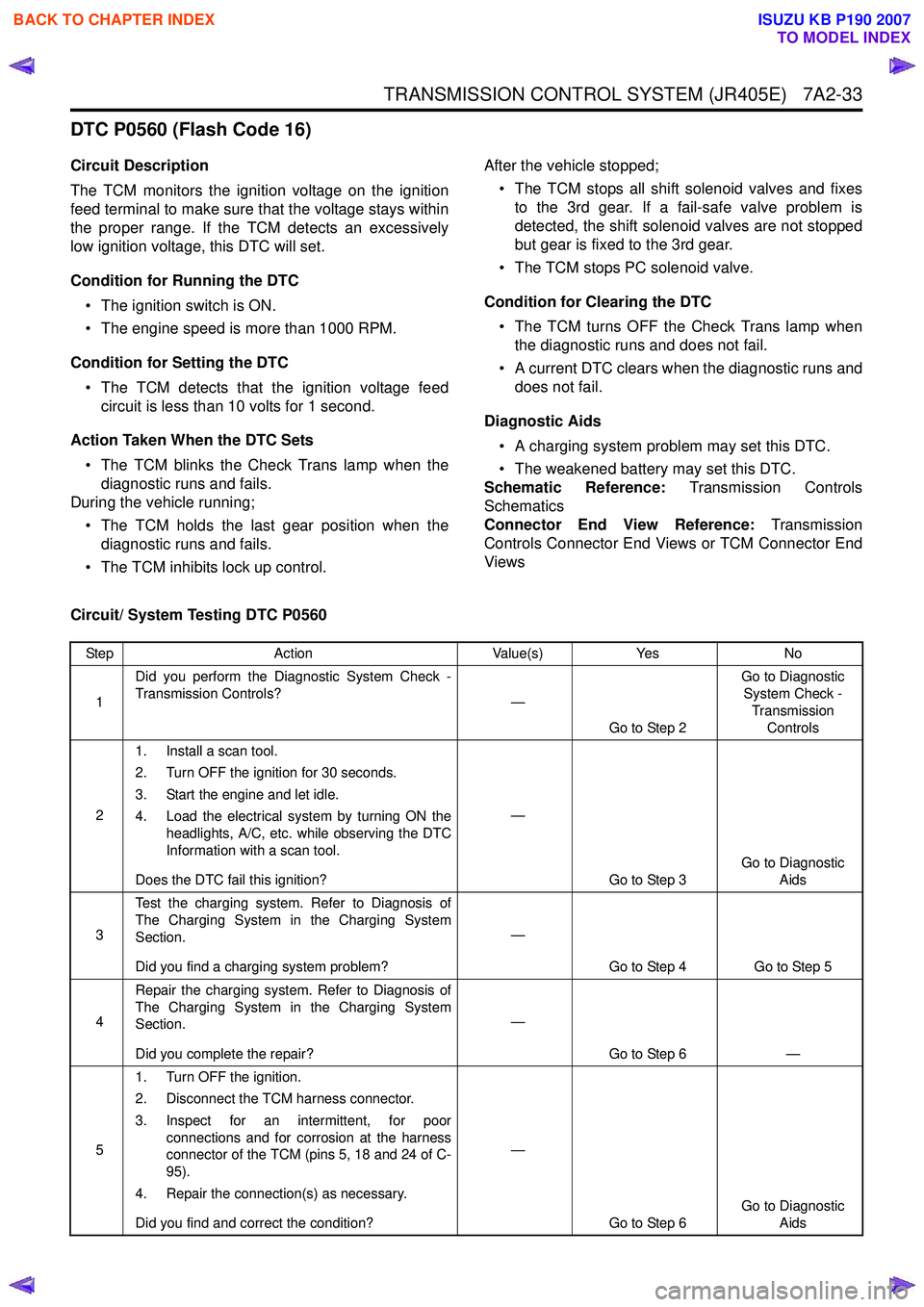
TRANSMISSION CONTROL SYSTEM (JR405E) 7A2-33
DTC P0560 (Flash Code 16)
Circuit Description
The TCM monitors the ignition voltage on the ignition
feed terminal to make sure that the voltage stays within
the proper range. If the TCM detects an excessively
low ignition voltage, this DTC will set.
Condition for Running the DTC • The ignition switch is ON.
• The engine speed is more than 1000 RPM.
Condition for Setting the DTC • The TCM detects that the ignition voltage feed circuit is less than 10 volts for 1 second.
Action Taken When the DTC Sets • The TCM blinks the Check Trans lamp when the diagnostic runs and fails.
During the vehicle running;
• The TCM holds the last gear position when the diagnostic runs and fails.
• The TCM inhibits lock up control. After the vehicle stopped;
• The TCM stops all shift solenoid valves and fixes to the 3rd gear. If a fail-safe valve problem is
detected, the shift solenoid valves are not stopped
but gear is fixed to the 3rd gear.
• The TCM stops PC solenoid valve.
Condition for Clearing the DTC • The TCM turns OFF the Check Trans lamp when the diagnostic runs and does not fail.
• A current DTC clears when the diagnostic runs and does not fail.
Diagnostic Aids • A charging system problem may set this DTC.
• The weakened battery may set this DTC.
Schematic Reference: Transmission Controls
Schematics
Connector End View Reference: Transmission
Controls Connector End Views or TCM Connector End
Views
Circuit/ System Testing DTC P0560
Step Action Value(s)Yes No
1 Did you perform the Diagnostic System Check -
Transmission Controls? —
Go to Step 2 Go to Diagnostic
System Check -
Transmission Controls
2 1. Install a scan tool.
2. Turn OFF the ignition for 30 seconds.
3. Start the engine and let idle.
4. Load the electrical system by turning ON the headlights, A/C, etc. while observing the DTC
Information with a scan tool.
Does the DTC fail this ignition? —
Go to Step 3 Go to Diagnostic
Aids
3 Test the charging system. Refer to Diagnosis of
The Charging System in the Charging System
Section.
Did you find a charging system problem? —
Go to Step 4 Go to Step 5
4 Repair the charging system. Refer to Diagnosis of
The Charging System in the Charging System
Section.
Did you complete the repair? —
Go to Step 6 —
5 1. Turn OFF the ignition.
2. Disconnect the TCM harness connector.
3. Inspect for an intermittent, for poor connections and for corrosion at the harness
connector of the TCM (pins 5, 18 and 24 of C-
95).
4. Repair the connection(s) as necessary.
Did you find and correct the condition? —
Go to Step 6 Go to Diagnostic
Aids
BACK TO CHAPTER INDEX
TO MODEL INDEX
ISUZU KB P190 2007
Page 4320 of 6020
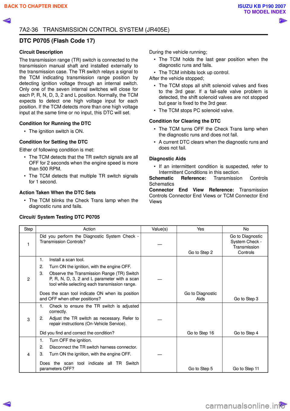
7A2-36 TRANSMISSION CONTROL SYSTEM (JR405E)
DTC P0705 (Flash Code 17)
Circuit Description
The transmission range (TR) switch is connected to the
transmission manual shaft and installed externally to
the transmission case. The TR switch relays a signal to
the TCM indicating transmission range position by
detecting ignition voltage through an internal switch.
Only one of the seven internal switches will close for
each P, R, N, D, 3, 2 and L position. Normally, the TCM
expects to detect one high voltage input for each
position. If the TCM detects more than one high voltage
input at the same time or no input, this DTC will set.
Condition for Running the DTC • The ignition switch is ON.
Condition for Setting the DTC
Either of following condition is met: • The TCM detects that the TR switch signals are all OFF for 2 seconds when the engine speed is more
than 500 RPM.
• The TCM detects that multiple TR switch signals for 1 second.
Action Taken When the DTC Sets • The TCM blinks the Check Trans lamp when the diagnostic runs and fails. During the vehicle running;
• The TCM holds the last gear position when the diagnostic runs and fails.
• The TCM inhibits lock up control.
After the vehicle stopped;
• The TCM stops all shift solenoid valves and fixes to the 3rd gear. If a fail-safe valve problem is
detected, the shift solenoid valves are not stopped
but gear is fixed to the 3rd gear.
• The TCM stops PC solenoid valve.
Condition for Clearing the DTC • The TCM turns OFF the Check Trans lamp when the diagnostic runs and does not fail.
• A current DTC clears when the diagnostic runs and does not fail.
Diagnostic Aids • If an intermittent condition is suspected, refer to Intermittent Conditions in this section.
Schematic Reference: Transmission Controls
Schematics
Connector End View Reference: Transmission
Controls Connector End Views or TCM Connector End
Views
Circuit/ System Testing DTC P0705
Step Action Value(s)Yes No
1 Did you perform the Diagnostic System Check -
Transmission Controls? —
Go to Step 2 Go to Diagnostic
System Check - Transmission Controls
2 1. Install a scan tool.
2. Turn ON the ignition, with the engine OFF.
3. Observe the Transmission Range (TR) Switch P, R, N, D, 3, 2 and L parameter with a scan
tool while selecting each transmission range.
Does the scan tool indicate ON when its position
and OFF when other positions? —
Go to Diagnostic Aids Go to Step 3
3 1. Check to ensure the TR switch is adjusted
correctly.
2. Adjust the TR switch as necessary. Refer to repair instructions (On-Vehicle Service).
Did you find and correct the condition? —
Go to Step 16 Go to Step 4
4 1. Turn OFF the ignition.
2. Disconnect the TR switch harness connector.
3. Turn ON the ignition, with the engine OFF.
Does the scan tool indicate all TR Switch
parameters OFF? —
Go to Step 5 Go to Step 11
BACK TO CHAPTER INDEX
TO MODEL INDEX
ISUZU KB P190 2007
Page 4324 of 6020

7A2-40 TRANSMISSION CONTROL SYSTEM (JR405E)
DTC P0710 (Flash Code 15)
Circuit Description
The transmission fluid temperature (TFT) sensor is
attached to the lower part of the valve body assembly.
The TFT sensor is a variable resistor and it measures
the temperature of the transmission fluid. The sensor
has a signal circuit and a low reference circuit. The
TCM supplies 2.5 volts to the signal circuit and a
ground for the low reference circuit. When the TFT
sensor is cold, the sensor resistance is high. When the
transmission fluid temperature increases, the sensor
resistance decreases. With high sensor resistance, the
TCM detects a high voltage on the signal circuit. With
lower sensor resistance, the TCM detects a lower
voltage on the signal circuit. If the TCM detects an
excessively low or high signal voltage, this DTC will set.
Condition for Running the DTC • The ignition switch is ON.
Condition for Setting the DTC
Either of following condition is met: • The TCM detects that the TFT sensor signal voltage is less than 0.1 volts (more than 146 °C
[295 °F]) when the selector lever is P or N range for
longer than 5 minutes.
• The TCM detects that the TFT sensor signal voltage is more than 2.43 volts (less than -40 °C [-
40 °F]) for 10 seconds when the vehicle speed is
more than 20 km/h (12 MPH).
Action Taken When the DTC Sets • The TCM does not blink the Check Trans lamp. • The TCM inhibits 4th gear. (If the engine speed is
more than 470 PRM for 10 minutes, shifting to 4th
gear is allowed.)
• The TCM inhibits lock up control. (If the engine speed is more than 470 RPM for 10 minutes, lock
up control is allowed.)
• The TCM uses a TFT substitution of 80 °C (176 °F)
for transmission control.
Condition for Clearing the DTC • current DTC clears when the diagnostic runs and does not fail.
Diagnostic Aids • If an intermittent condition is suspected, refer to Intermittent Conditions in this section.
• Use the Temperature vs. Resistance table to test the TFT sensor at various temperature levels to
evaluate the possibility of a skewed sensor. A
skewed sensor could result in poor driveability
(poor shift quality) concerns.
Test Description
The numbers below refer to the step number on the
Circuit/ System Testing.
5. If the TFT sensor signal circuit is shorted to ground,
A/T Oil Temp lamp turns ON and the TCM switches
shift map to the high temperature mode until this DTC
is set.
Schematic Reference: Transmission Controls
Schematics
Connector End View Reference: Transmission
Controls Connector End Views or TCM Connector End
Views
Circuit/ System Testing DTC P0710
Step Action Value(s)Yes No
1 Did you perform the Diagnostic System Check -
Transmission Controls? —
Go to Step 2 Go to Diagnostic
System Check -
Transmission Controls
2 1. Install a scan tool.
2. Turn ON the ignition, with the engine OFF.
3. Observe the Transmission Fluid Temperature (TFT) parameter with a scan tool within 5
minutes from the ignition switch is ON.
Is the TFT parameter more than the specified
value? 146
°C (295 °F)
Go to Step 4 Go to Step 3
3 Is the TFT parameter less than the specified value
at Step 2? -40
°C (-40 °F)
Go to Step 7 Go to Diagnostic
Aids
BACK TO CHAPTER INDEX
TO MODEL INDEX
ISUZU KB P190 2007
Page 4328 of 6020

7A2-44 TRANSMISSION CONTROL SYSTEM (JR405E)
DTC P0717 (Flash Code 14)
Circuit Description
The input shaft speed (ISS) sensor is located on right-
hand of the transmission case. The ISS sensor is a hall
effect element type sensor, which generates a square
wave signal pulse based on the reverse & high clutch
drum rotational speed (32 pulses per a rotation of the
reverse & high clutch drum). The sensor has the
following circuits.
• Ignition voltage feed circuit
• Low reference circuit
• ISS sensor signal circuit
The TCM calculates the turbine speed by the ISS
sensor signal, and uses it to calculate torque converter
slip speed and gear ratio. If the TCM detects
excessively low input shaft speed during the vehicle
running, this DTC will set.
Condition for Running the DTC • The ignition switch is ON.
• The engine speed is more than 1500 RPM.
• The vehicle speed is more than 40 km/h (24 MPH).
• The selector lever is forward range.
Condition for Setting the DTC • The TCM detects that the input shaft speed is less than 300 RPM for 2 seconds.
Action Taken When the DTC Sets • The TCM blinks the Check Trans lamp when the diagnostic runs and fails. During the vehicle running;
• The TCM holds the last gear position when the diagnostic runs and fails.
• The TCM inhibits lock up control.
After the vehicle stopped;
• The TCM stops all shift solenoid valves and fixes to the 3rd gear.
• The TCM stops PC solenoid valve.
Condition for Clearing the DTC • The TCM turns OFF the Check Trans lamp when the diagnostic runs and does not fail.
• A current DTC clears when the diagnostic runs and does not fail.
Diagnostic Aids • If an intermittent condition is suspected, refer to Intermittent Conditions in this section.
• Electromagnetic interference in the ISS sensor circuits may set this DTC.
• An intermittent ISS sensor signal pulse may set this DTC.
• Ensure the ISS sensor is tight.
Schematic Reference: Transmission Controls
Schematics
Connector End View Reference: Transmission
Controls Connector End Views or TCM Connector End
Views
Circuit/ System Testing DTC P0717
Step Action Value(s)Yes No
1 Did you perform the Diagnostic System Check -
Transmission Controls? —
Go to Step 2 Go to Diagnostic
System Check -
Transmission Controls
2 1. Install a scan tool.
2. Turn OFF the ignition for 30 seconds.
3. Lift the driving wheels or drive the vehicle.
4. Operate the vehicle within the Conditions for Running the DTC.
5. Monitor the DTC Information with a scan tool.
Does the DTC fail this ignition? —
Go to Step 3 Go to Diagnostic
Aids
3 1. Turn OFF the ignition.
2. Disconnect the input shaft speed (ISS) sensor harness connector.
3. Turn ON the ignition, with the engine OFF.
4. Connect a test lamp between the ignition voltage feed circuit (pin 2 of E-31) and a
known good ground.
Does the test lamp illuminate? —
Go to Step 4 Go to Step 6
BACK TO CHAPTER INDEX
TO MODEL INDEX
ISUZU KB P190 2007
Page 4331 of 6020

TRANSMISSION CONTROL SYSTEM (JR405E) 7A2-47
DTC P0722 (Flash Code 11)
Circuit Description
The output shaft speed (OSS) sensor is located on
right-hand of the transmission case near the
transmission range switch. The OSS sensor is a hall
effect element type sensor, which generates a square
wave signal pulse based on the parking gear rotational
speed that is connected to output shaft (16 pulses per a
rotation of the parking gear). The sensor has the
following circuits.
• Ignition voltage feed circuit
• Low reference circuit
• OSS sensor signal circuit
The TCM calculates the vehicle speed by the OSS
sensor signal, and uses it to determine appropriate shift
points and calculate gear ratio. The 2WD vehicle
outputs the vehicle speed signal from the TCM to the
engine control module (ECM) and the vehicle speed
meter via output signal line. If the TCM detects
excessively low output shaft speed during the vehicle
running, this DTC will set.
Condition for Running the DTC • The ignition switch is ON.
• The input shaft speed is more than 1000 RPM.
• The selector lever is forward range for longer than 25 seconds.
Condition for Setting the DTC • The TCM detects that the vehicle speed is less than 5 km/h (3 MPH) for 5 seconds.
Action Taken When the DTC Sets • The TCM blinks the Check Trans lamp when the diagnostic runs and fails. During the vehicle running;
• The TCM holds the last gear position when the diagnostic runs and fails.
• The TCM inhibits lock up control.
After the vehicle stopped;
• The TCM stops all shift solenoid valves and fixes to the 3rd gear. If a fail-safe valve problem is
detected, the shift solenoid valves are not stopped
but gear is fixed to the 3rd gear.
• The TCM stops PC solenoid valve.
Condition for Clearing the DTC • The TCM turns OFF the Check Trans lamp when the diagnostic runs and does not fail.
• A current DTC clears when the diagnostic runs and does not fail.
Diagnostic Aids • If an intermittent condition is suspected, refer to Intermittent Conditions in this section.
• Electromagnetic interference in the OSS sensor circuits may set this DTC.
• An intermittent OSS sensor signal pulse may set this DTC.
• Ensure the OSS sensor is tight.
Schematic Reference: Transmission Controls
Schematics
Connector End View Reference: Transmission
Controls Connector End Views or TCM Connector End
Views
Circuit/ System Testing DTC P0722
Step Action Value(s)Yes No
1 Did you perform the Diagnostic System Check -
Transmission Controls? —
Go to Step 2 Go to Diagnostic
System Check - Transmission Controls
2 Drive the vehicle while observing the Vehicle
Speed parameter with a scan tool.
Does the scan tool indicate correct vehicle speed? —
Go to Step 3 Go to Diagnostic
Aids
3 1. Turn OFF the ignition.
2. Disconnect the output shaft speed (OSS) sensor harness connector.
3. Turn ON the ignition, with the engine OFF.
4. Connect a test lamp between the ignition voltage feed circuit (pin 2 of E-30) and a
known good ground.
Does the test lamp illuminate? —
Go to Step 4 Go to Step 6
BACK TO CHAPTER INDEX
TO MODEL INDEX
ISUZU KB P190 2007