compression ratio ISUZU KB P190 2007 Workshop Repair Manual
[x] Cancel search | Manufacturer: ISUZU, Model Year: 2007, Model line: KB P190, Model: ISUZU KB P190 2007Pages: 6020, PDF Size: 70.23 MB
Page 125 of 6020
HEATER AND AIR CONDITIONING 1-91
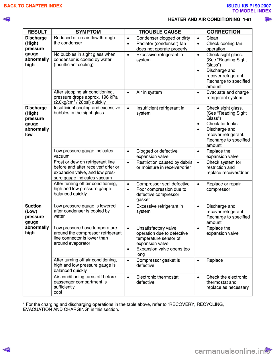
RESULT SYMPTOM TROUBLE CAUSE CORRECTION
Reduced or no air flow through
the condenser
•
Condenser clogged or dirty
• Radiator (condenser) fan
does not operate properly •
Clean
• Check cooling fan
operation
No bubbles in sight glass when
condenser is cooled by water
(Insufficient cooling)
•
Excessive refrigerant in
system
•
Check sight glass.
(See “Reading Sight
Glass”)
• Discharge and
recover refrigerant.
Recharge to specified
amount
Discharge
(High)
pressure
gauge
abnormally
high
After stopping air conditioning,
pressure drops approx. 196 kPa
(2.0kg/cm
2 / 28psi) quickly •
Air in system
•
Evacuate and charge
refrigerant system
Insufficient cooling and excessive
bubbles in the sight glass
•
Insufficient refrigerant in
system
•
Check sight glass.
(See “Reading Sight
Glass”)
• Check for leaks
• Discharge and
recover refrigerant.
Recharge to specified
amount
Low pressure gauge indicates
vacuum •
Clogged or defective
expansion valve •
Replace the
expansion valve
Frost or dew on refrigerant line
before and after receiver/ drier or
expansion valve, and low pres-
sure gauge indicates vacuum •
Restriction caused by debris
or moisture in receiver/drier
•
Check system for
restriction and
replace receiver/drier
Discharge
(High)
pressure
gauge
abnormally
low
After turning off air conditioning,
high and low pressure gauge
balanced quickly
•
Compressor seal defective
• Poor compression due to
defective compressor
gasket •
Replace or repair
compressor
Low pressure gauge is lowered
after condenser is cooled by
water
•
Excessive refrigerant in
system
•
Discharge and
recover refrigerant
Recharge to specified
amount
Low pressure hose temperature
around the compressor refrigerant
line connector is lower than
around evaporator
•
Unsatisfactory valve
operation due to defective
temperature sensor of
expansion valve
• Expansion valve opens too
long •
Replace the
expansion valve
After turning off air conditioning,
high and low pressure gauge is
balanced quickly •
Compressor gasket is
defective
•
Replace
Suction
(Low)
pressure
gauge
abnormally
high
Air conditioning turns off before
passenger compartment is
sufficiently
cool •
Electronic thermostat
defective
•
Check the electronic
thermostat and
replace as necessary
* For the charging and discharging operations in the table above, refer to “RECOVERY, RECYCLING,
EVACUATION AND CHARGING” in this section.
BACK TO CHAPTER INDEX
TO MODEL INDEX
ISUZU KB P190 2007
Page 562 of 6020
4C1-58 FRONT WHEEL DRIVE
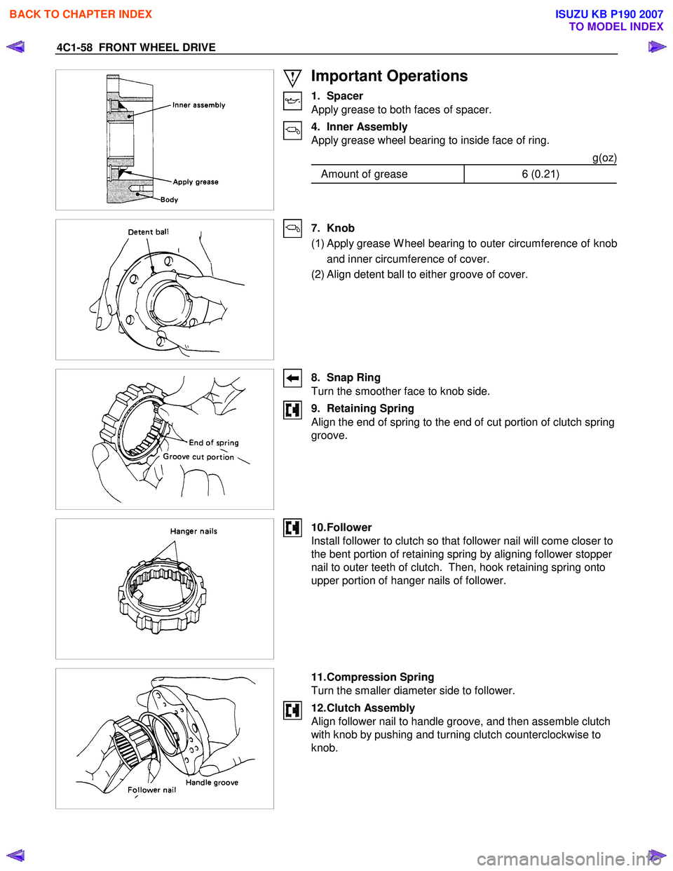
Important Operations
1. Spacer
Apply grease to both faces of spacer.
4. Inner Assembly
Apply grease wheel bearing to inside face of ring.
g(oz)
Amount of grease 6 (0.21)
7. Knob
( 1 ) Apply grease W heel bearing to outer circumference of knob
and inner circumference of cover.
(2) Align detent ball to either groove of cover.
8. Snap Ring
Turn the smoother face to knob side.
9. Retaining Spring
Align the end of spring to the end of cut portion of clutch spring
groove.
10. Follower
Install follower to clutch so that follower nail will come closer to
the bent portion of retaining spring by aligning follower stopper
nail to outer teeth of clutch. Then, hook retaining spring onto
upper portion of hanger nails of follower.
11. Compression Spring
Turn the smaller diameter side to follower.
12. Clutch Assembly
Align follower nail to handle groove, and then assemble clutch
with knob by pushing and turning clutch counterclockwise to
knob.
BACK TO CHAPTER INDEX
TO MODEL INDEX
ISUZU KB P190 2007
Page 809 of 6020
6A – 4 ENGINE MECHANICAL
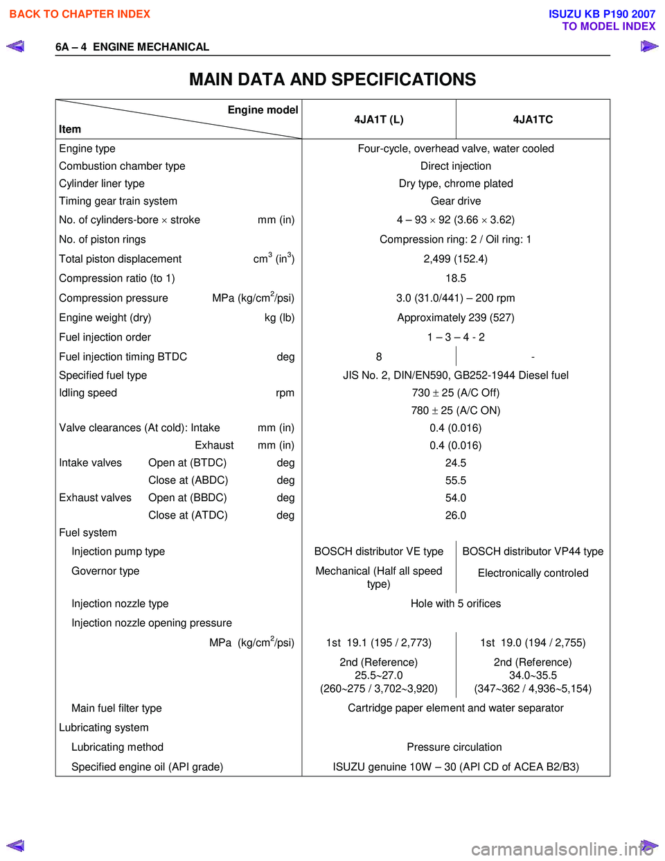
MAIN DATA AND SPECIFICATIONS
Engine model
Item 4JA1T (L)
4JA1TC
Engine type
Combustion chamber type
Cylinder liner type
Timing gear train system Four-cycle, overhead valve, water cooled
Direct injection
Dry type, chrome plated Gear drive
No. of cylinders-bore × stroke mm (in) 4 – 93 × 92 (3.66 × 3.62)
No. of piston rings Compression ring: 2 / Oil ring: 1
Total piston displacement cm3 (in3)
Compression ratio (to 1) 2,499 (152.4)
18.5
Compression pressure MPa (kg/cm2/psi) 3.0 (31.0/441) – 200 rpm
Engine weight (dry) kg (lb)Approximately 239 (527)
Fuel injection order 1 – 3 – 4 - 2
Fuel injection timing BTDC deg8 -
Specified fuel type
Idling speed rpm
Valve clearances (At cold): Intake mm (in)
Exhaust mm (in)
Intake valves Open at (BTDC) deg
Close at (ABDC) deg
Exhaust valves Open at (BBDC) deg
Close at (ATDC) deg
Fuel system JIS No. 2, DIN/EN590, GB252-1944 Diesel fuel
730 ± 25 (A/C Off)
780 ± 25 (A/C ON)
0.4 (0.016)
0.4 (0.016) 24.5
55.5
54.0
26.0
Injection pump type BOSCH distributor VE type BOSCH distributor VP44 type
Governor type Mechanical (Half all speed
type) Electronically controled
Injection nozzle type
Injection nozzle opening pressure Hole with 5 orifices
MPa (kg/cm2/psi) 1st 19.1 (195 / 2,773) 1st 19.0 (194 / 2,755)
2nd (Reference)
25.5 ∼27.0
(260 ∼275 / 3,702 ∼3,920) 2nd (Reference)
34.0 ∼35.5
(347 ∼362 / 4,936 ∼5,154)
Main fuel filter type
Lubricating system
Lubricating method Cartridge paper element and water separator
Pressure circulation
Specified engine oil (API grade) ISUZU genuine 10W – 30 (API CD of ACEA B2/B3)
BACK TO CHAPTER INDEX
TO MODEL INDEX
ISUZU KB P190 2007
Page 811 of 6020
6A – 6 ENGINE MECHANICAL
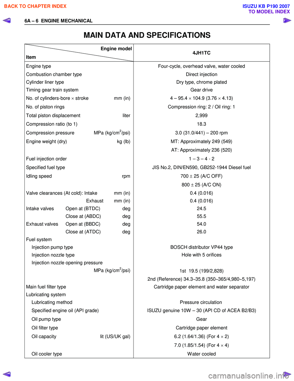
MAIN DATA AND SPECIFICATIONS
Engine model
Item 4JH1TC
Engine type
Four-cycle, overhead valve, water cooled
Combustion chamber type Direct injection
Cylinder liner type
Timing gear train system Dry type, chrome plated
Gear drive
No. of cylinders-bore × stroke mm (in) 4 – 95.4 × 104.9 (3.76 × 4.13)
No. of piston rings Compression ring: 2 / Oil ring: 1
Total piston displacement liter
Compression ratio (to 1) 2,999
18.3
Compression pressure MPa (kg/cm2/psi) 3.0 (31.0/441) – 200 rpm
Engine weight (dry) kg (lb)MT: Approximately 249 (549)
AT: Approximately 236 (520)
Fuel injection order 1 – 3 – 4 - 2
Specified fuel type JIS No.2, DIN/EN590, GB252-1944 Diesel fuel
Idling speed rpm
700 ± 25 (A/C OFF)
800 ± 25 (A/C ON)
Valve clearances (At cold): Intake mm (in)
Exhaust mm (in)
Intake valves Open at (BTDC) deg
Close at (ABDC) deg
Exhaust valves Open at (BBDC) deg
Close at (ATDC) deg
Fuel system
Injection pump type 0.4 (0.016)
0.4 (0.016) 24.5
55.5
54.0
26.0
BOSCH distributor VP44 type
Injection nozzle type
Injection nozzle opening pressure
MPa (kg/cm
2/psi) Hole with 5 orifices
1st 19.5 (199/2,828)
2nd (Reference) 34.3 ∼35.8 (350 ∼365/4,980 ∼5,197)
Main fuel filter type
Lubricating system
Lubricating method Cartridge paper element and water separator
Pressure circulation
Specified engine oil (API grade) ISUZU genuine 10W – 30 (API CD of ACEA B2/B3)
Oil pump type
Oil filter type Gear
Cartridge paper element
Oil capacity lit (US/UK gal)
6.2 (1.64/1.36) (For 4
× 2)
7.0 (1.85/1.54) (For 4 × 4)
Oil cooler type W ater cooled
BACK TO CHAPTER INDEX
TO MODEL INDEX
ISUZU KB P190 2007
Page 836 of 6020
ENGINE MECHANICAL 6A – 31
VALVE CLEARANCE ADJUSTMENT
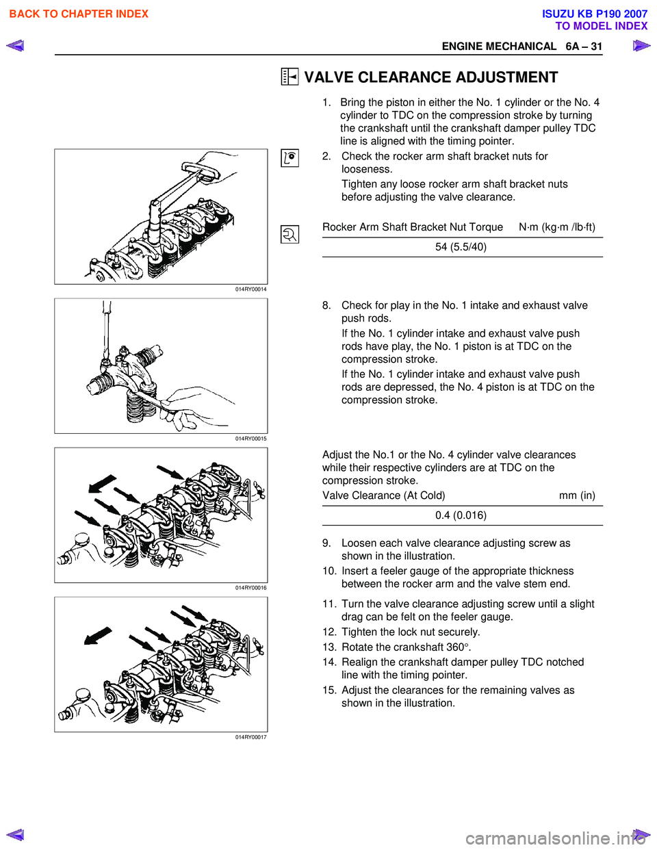
1. Bring the piston in either the No. 1 cylinder or the No. 4 cylinder to TDC on the compression stroke by turning
the crankshaft until the crankshaft damper pulley TDC
line is aligned with the timing pointer.
014RY00014
2. Check the rocker arm shaft bracket nuts for
looseness.
Tighten any loose rocker arm shaft bracket nuts
before adjusting the valve clearance.
Rocker Arm Shaft Bracket Nut Torque N·m (kg·m /lb·ft)
54 (5.5/40)
014RY00015
8. Check for play in the No. 1 intake and exhaust valve
push rods.
If the No. 1 cylinder intake and exhaust valve push
rods have play, the No. 1 piston is at TDC on the
compression stroke.
If the No. 1 cylinder intake and exhaust valve push
rods are depressed, the No. 4 piston is at TDC on the
compression stroke.
014RY00016
Adjust the No.1 or the No. 4 cylinder valve clearances
while their respective cylinders are at TDC on the
compression stroke.
Valve Clearance (At Cold) mm (in)
0.4 (0.016)
9. Loosen each valve clearance adjusting screw as
shown in the illustration.
10. Insert a feeler gauge of the appropriate thickness between the rocker arm and the valve stem end.
014RY00017
11. Turn the valve clearance adjusting screw until a slight
drag can be felt on the feeler gauge.
12. Tighten the lock nut securely.
13. Rotate the crankshaft 360 °.
14. Realign the crankshaft damper pulley TDC notched line with the timing pointer.
15. Adjust the clearances for the remaining valves as shown in the illustration.
BACK TO CHAPTER INDEX
TO MODEL INDEX
ISUZU KB P190 2007
Page 903 of 6020
6A – 98 ENGINE MECHANICAL
RTW 36ASH002001
6. Piston Ring
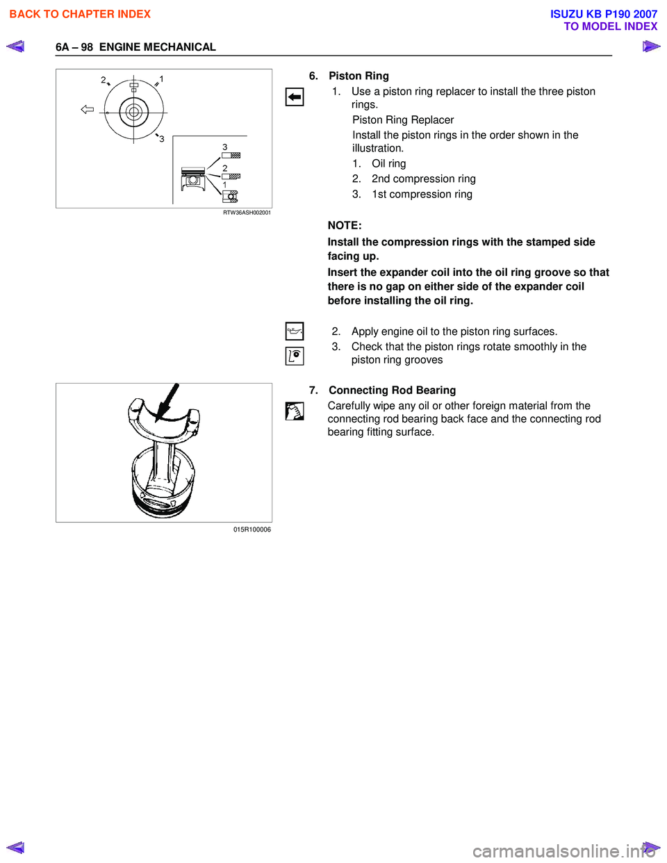
1. Use a piston ring replacer to install the three piston rings.
Piston Ring Replacer
Install the piston rings in the order shown in the
illustration.
1. Oil ring
2. 2nd compression ring
3. 1st compression ring
NOTE:
Install the compression rings with the stamped side
facing up.
Insert the expander coil into the oil ring groove so that
there is no gap on either side of the expander coil
before installing the oil ring.
2. Apply engine oil to the piston ring surfaces.
3. Check that the piston rings rotate smoothly in the piston ring grooves
7. Connecting Rod Bearing
Carefully wipe any oil or other foreign material from the
connecting rod bearing back face and the connecting rod
bearing fitting surface.
015R100006
BACK TO CHAPTER INDEX
TO MODEL INDEX
ISUZU KB P190 2007
Page 912 of 6020
ENGINE MECHANICAL 6A – 107
RTW 36ASH002001
11. Piston and Connecting Rod with Upper Bearing
12. Connecting Rod Bearing Cap with Lower Bearing
1. Apply a coat of engine oil to the circumference of each piston ring and piston.
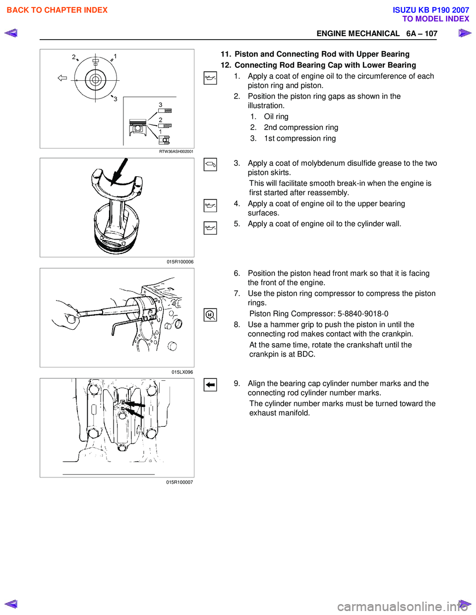
2. Position the piston ring gaps as shown in the illustration.
1. Oil ring
2. 2nd compression ring
3. 1st compression ring
3. Apply a coat of molybdenum disulfide grease to the two
piston skirts.
This will facilitate smooth break-in when the engine is
first started after reassembly.
4. Apply a coat of engine oil to the upper bearing surfaces.
5. Apply a coat of engine oil to the cylinder wall.
6. Position the piston head front mark so that it is facing
the front of the engine.
7. Use the piston ring compressor to compress the piston rings.
Piston Ring Compressor: 5-8840-9018-0
8. Use a hammer grip to push the piston in until the connecting rod makes contact with the crankpin.
At the same time, rotate the crankshaft until the
crankpin is at BDC.
9. Align the bearing cap cylinder number marks and the connecting rod cylinder number marks.
The cylinder number marks must be turned toward the
exhaust manifold.
015LX096
015R100007 015R100006
BACK TO CHAPTER INDEX
TO MODEL INDEX
ISUZU KB P190 2007
Page 942 of 6020
ENGINE MECHANICAL 6A – 137
SPECIAL TOOLS
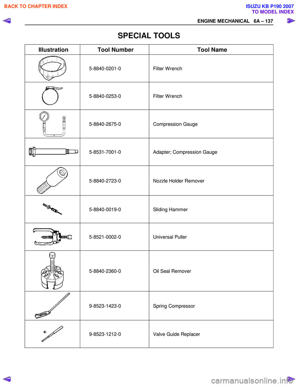
Illustration Tool Number Tool Name
5-8840-0201-0 Filter
W rench
5-8840-0253-0 Filter
W rench
5-8840-2675-0 Compression Gauge
5-8531-7001-0
Adapter; Compression Gauge
5-8840-2723-0
Nozzle Holder Remover
5-8840-0019-0 Sliding Hammer
5-8521-0002-0 Universal Puller
5-8840-2360-0 Oil Seal Remover
9-8523-1423-0 Spring
Compressor
9-8523-1212-0 Valve Guide Replacer
BACK TO CHAPTER INDEX
TO MODEL INDEX
ISUZU KB P190 2007
Page 1294 of 6020
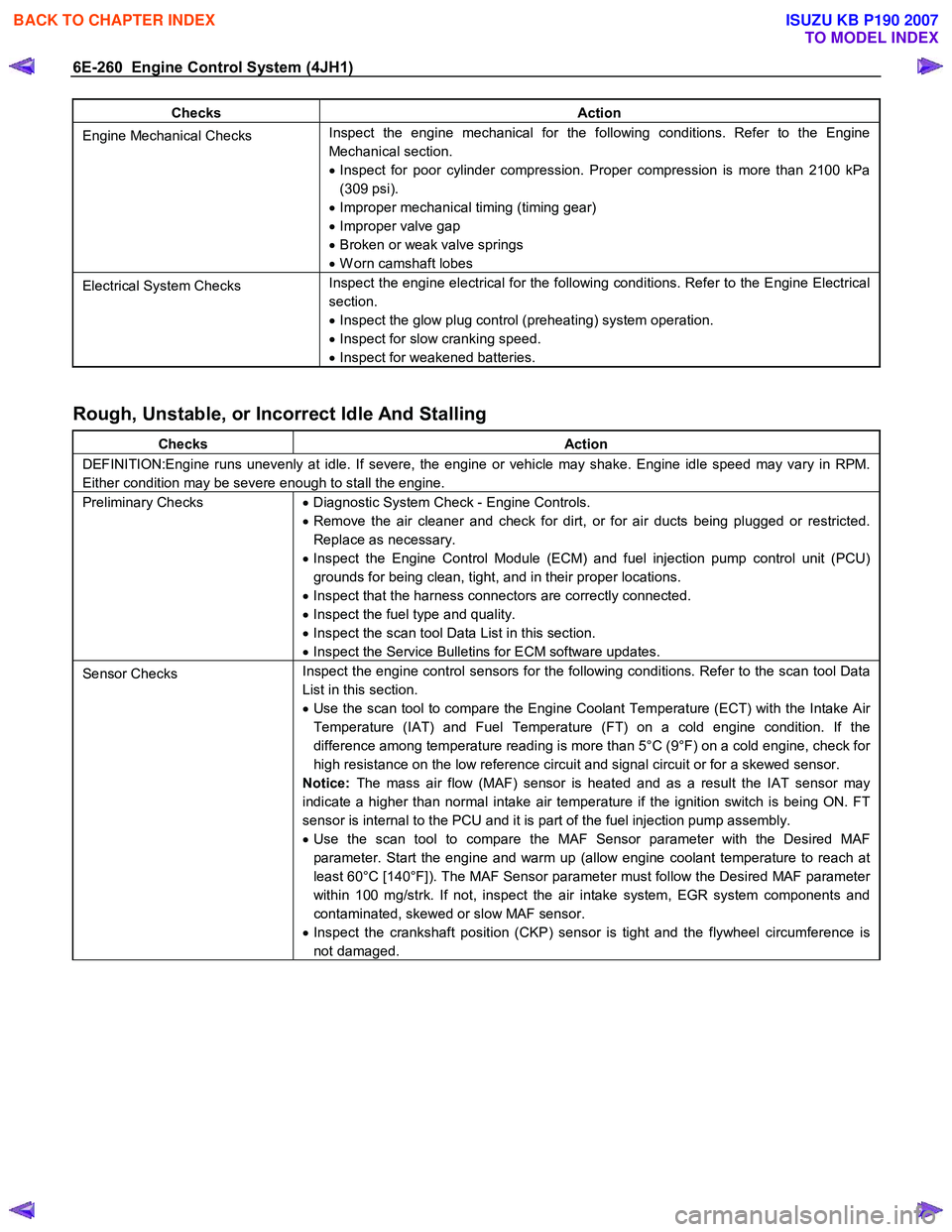
6E-260 Engine Control System (4JH1)
Checks Action
Engine Mechanical Checks Inspect the engine mechanical for the following conditions. Refer to the Engine
Mechanical section.
• Inspect for poor cylinder compression. Proper compression is more than 2100 kPa
(309 psi).
• Improper mechanical timing (timing gear)
• Improper valve gap
• Broken or weak valve springs
• W orn camshaft lobes
Electrical System Checks Inspect the engine electrical for the following conditions. Refer to the Engine Electrical
section.
• Inspect the glow plug control (preheating) system operation.
• Inspect for slow cranking speed.
• Inspect for weakened batteries.
Rough, Unstable, or Incorrect Idle And Stalling
Checks Action
DEFINITION:Engine runs unevenly at idle. If severe, the engine or vehicle may shake. Engine idle speed may vary in RPM.
Either condition may be severe enough to stall the engine.
Preliminary Checks • Diagnostic System Check - Engine Controls.
• Remove the air cleaner and check for dirt, or for air ducts being plugged or restricted.
Replace as necessary.
• Inspect the Engine Control Module (ECM) and fuel injection pump control unit (PCU)
grounds for being clean, tight, and in their proper locations.
• Inspect that the harness connectors are correctly connected.
• Inspect the fuel type and quality.
• Inspect the scan tool Data List in this section.
• Inspect the Service Bulletins for ECM software updates.
Sensor Checks Inspect the engine control sensors for the following conditions. Refer to the scan tool Data
List in this section.
• Use the scan tool to compare the Engine Coolant Temperature (ECT) with the Intake Air
Temperature (IAT) and Fuel Temperature (FT) on a cold engine condition. If the
difference among temperature reading is more than 5°C (9°F) on a cold engine, check for
high resistance on the low reference circuit and signal circuit or for a skewed sensor.
Notice: The mass air flow (MAF) sensor is heated and as a result the IAT sensor may
indicate a higher than normal intake air temperature if the ignition switch is being ON. FT
sensor is internal to the PCU and it is part of the fuel injection pump assembly.
• Use the scan tool to compare the MAF Sensor parameter with the Desired MAF
parameter. Start the engine and warm up (allow engine coolant temperature to reach at
least 60°C [140°F]). The MAF Sensor parameter must follow the Desired MAF parameter
within 100 mg/strk. If not, inspect the air intake system, EGR system components and
contaminated, skewed or slow MAF sensor.
• Inspect the crankshaft position (CKP) sensor is tight and the flywheel circumference is
not damaged.
BACK TO CHAPTER INDEX
TO MODEL INDEX
ISUZU KB P190 2007
Page 1295 of 6020
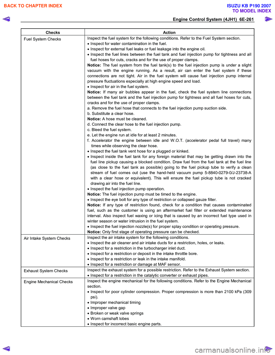
Engine Control System (4JH1) 6E-261
Checks Action
Fuel System Checks Inspect the fuel system for the following conditions. Refer to the Fuel System section.
• Inspect for water contamination in the fuel.
• Inspect for external fuel leaks or fuel leakage into the engine oil.
• Inspect the fuel lines between the fuel tank and fuel injection pump for tightness and all
fuel hoses for cuts, cracks and for the use of proper clamps.
Notice: The fuel system from the fuel tank(s) to the fuel injection pump is under a slight
vacuum with the engine running. As a result, air can enter the fuel system if these
connections are not tight. Air in the fuel system will cause fuel injection pump internal
pressure fluctuations especially at high engine speed and load.
• Inspect for air in the fuel system.
Notice: If many air bubbles appear in the fuel, check the fuel system line connections
between the fuel tank and the fuel injection pump for tightness and all fuel hoses for cuts,
cracks and for the use of proper clamps.
a. Remove the fuel hose that connects to the fuel injection pump suction side.
b. Substitute a clear hose.
Notice: A hose must be cleaned.
d. Connect the clear hose to the fuel injection pump.
c. Bleed the fuel system.
e. Let the engine run at idle for at least 2 minutes.
f. Accelerator the engine between idle and W .O.T. (accelerator pedal full travel) many times while observing the clear hose.
• Inspect the fuel tank vent hose for a plugged or kinked.
• Inspect inside the fuel tank for any foreign material that may be getting drawn into the
fuel line pickup causing a blocked condition. Draw fuel from the fuel tank at the fuel line
(as close to the fuel tank as possible) going to the fuel pickup tube to verify a clean
stream of fuel comes out (use the hand-held vacuum pump 5-8840-0279-0/J-23738-A
with a clear hose or equivalent). This will ensure the fuel pickup tube is not cracked
drawing air into the fuel line.
• Inspect the fuel injection pump operation.
Notice: The fuel injection pump must be timed to the engine.
• Inspect the eye bolt for any type of restriction or collapsed gauze filter.
Notice: If any type of restriction found, check for a condition that causes contaminated
fuel, such as the customer is using an aftermarket fuel filter or extended maintenance
interval. Also inspect fuel waxing or icing that is caused by an incorrect fuel type used in
winter season or water intrusion in the fuel system.
• Inspect the fuel injection nozzle(s) for proper splay condition or operating pressure.
Notice: Only first stage of operating pressure can be checked.
Air Intake System Checks Inspect the air intake system for the following conditions.
• Inspect the air cleaner and air intake ducts for a restriction, holes, or leaks.
• Inspect for a restriction in the turbocharger inlet duct.
• Inspect for a restriction or deposit in the intake throttle bore.
• Inspect for a restriction or leak in the intake manifold.
• Inspect for a restriction or damage at MAF sensor.
Exhaust System Checks Inspect the exhaust system for a possible restriction. Refer to the Exhaust System section.
• Inspect for a restriction in the catalytic converter or exhaust pipes.
Engine Mechanical Checks Inspect the engine mechanical for the following conditions. Refer to the Engine Mechanical
section.
• Inspect for poor cylinder compression. Proper compression is more than 2100 kPa (309
psi).
• Improper mechanical timing
• Improper valve gap
• Broken or weak valve springs
• W orn camshaft lobes
• Inspect for incorrect basic engine parts.
BACK TO CHAPTER INDEX
TO MODEL INDEX
ISUZU KB P190 2007