FLASH CODE ISUZU KB P190 2007 Workshop Repair Manual
[x] Cancel search | Manufacturer: ISUZU, Model Year: 2007, Model line: KB P190, Model: ISUZU KB P190 2007Pages: 6020, PDF Size: 70.23 MB
Page 4011 of 6020

TRANSMISSION CONTROL SYSTEM (AW30–40LE) 7A2-45
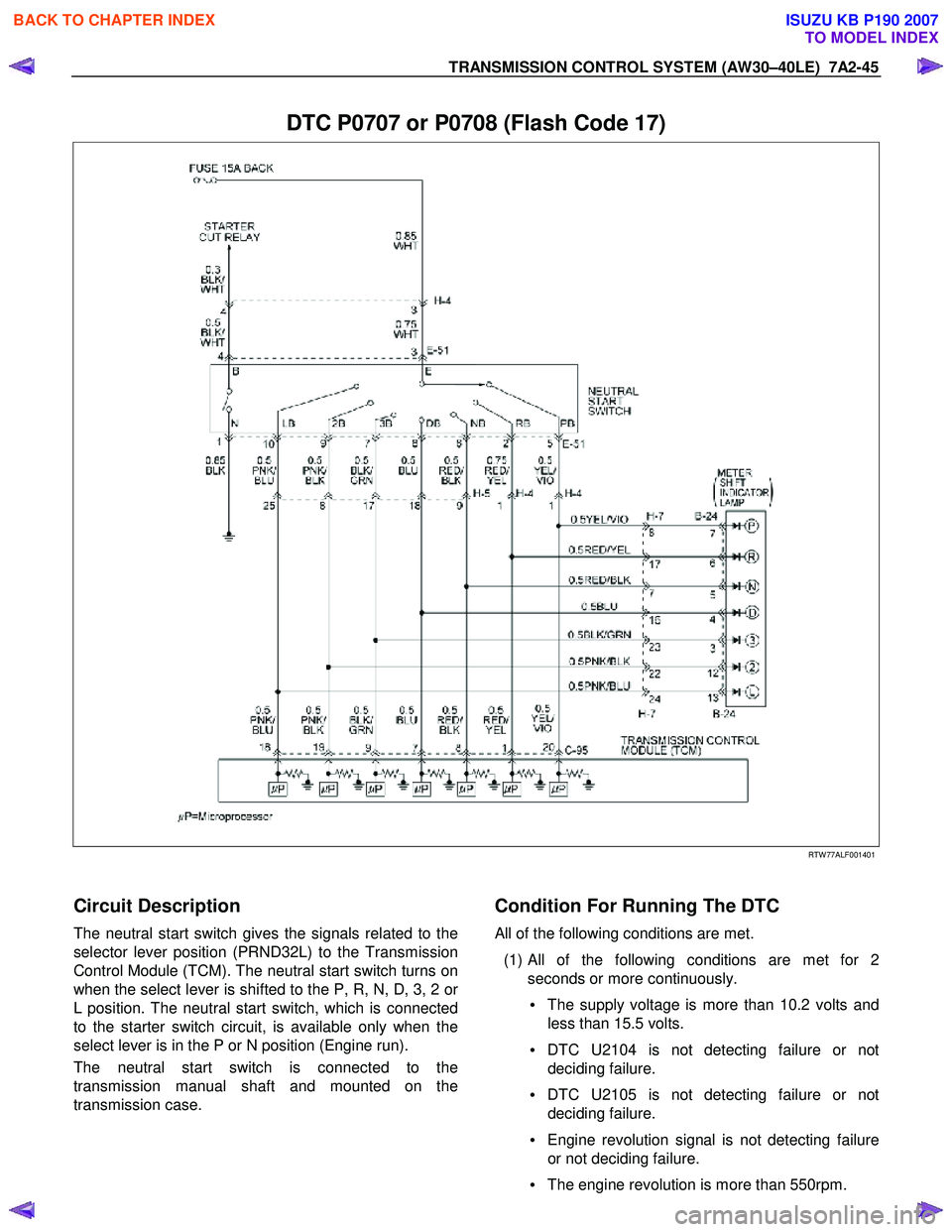
DTC P0707 or P0708 (Flash Code 17)
RTW 77ALF001401
Circuit Description
The neutral start switch gives the signals related to the
selector lever position (PRND32L) to the Transmission
Control Module (TCM). The neutral start switch turns on
when the select lever is shifted to the P, R, N, D, 3, 2 o
r
L position. The neutral start switch, which is connected
to the starter switch circuit, is available only when the
select lever is in the P or N position (Engine run).
The neutral start switch is connected to the
transmission manual shaft and mounted on the
transmission case.
Condition For Running The DTC
All of the following conditions are met.
(1) All of the following conditions are met for 2 seconds or more continuously.
• The supply voltage is more than 10.2 volts and
less than 15.5 volts.
• DTC U2104 is not detecting failure or not
deciding failure.
• DTC U2105 is not detecting failure or not
deciding failure.
• Engine revolution signal is not detecting failure
or not deciding failure.
• The engine revolution is more than 550rpm.
BACK TO CHAPTER INDEX
TO MODEL INDEX
ISUZU KB P190 2007
Page 4015 of 6020

TRANSMISSION CONTROL SYSTEM (AW30–40LE) 7A2-49
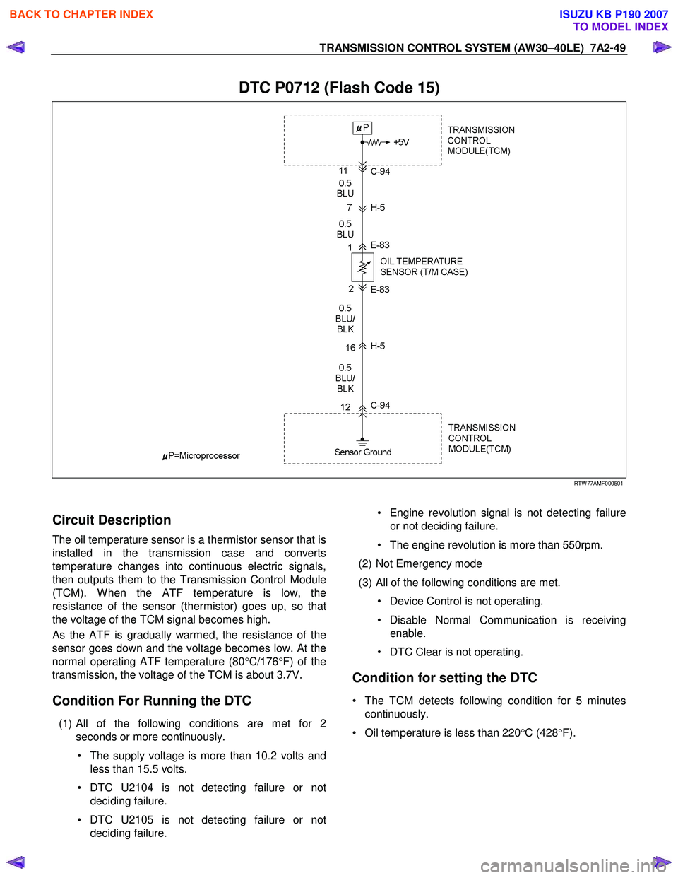
DTC P0712 (Flash Code 15)
RTW 77AMF000501
Circuit Description
The oil temperature sensor is a thermistor sensor that is
installed in the transmission case and converts
temperature changes into continuous electric signals,
then outputs them to the Transmission Control Module
(TCM). W hen the ATF temperature is low, the
resistance of the sensor (thermistor) goes up, so that
the voltage of the TCM signal becomes high.
As the ATF is gradually warmed, the resistance of the
sensor goes down and the voltage becomes low. At the
normal operating ATF temperature (80 °C/176 °F) of the
transmission, the voltage of the TCM is about 3.7V.
Condition For Running the DTC
(1) All of the following conditions are met for 2
seconds or more continuously.
• The supply voltage is more than 10.2 volts and less than 15.5 volts.
• DTC U2104 is not detecting failure or not deciding failure.
• DTC U2105 is not detecting failure or not deciding failure.
• Engine revolution signal is not detecting failure
or not deciding failure.
• The engine revolution is more than 550rpm.
(2) Not Emergency mode
(3) All of the following conditions are met. • Device Control is not operating.
• Disable Normal Communication is receiving enable.
• DTC Clear is not operating.
Condition for setting the DTC
• The TCM detects following condition for 5 minutes continuously.
• Oil temperature is less than 220 °C (428 °F).
BACK TO CHAPTER INDEX
TO MODEL INDEX
ISUZU KB P190 2007
Page 4018 of 6020

7A2-52 TRANSMISSION CONTROL SYSTEM (AW30–40LE)
DTC P0713 (Flash Code 16)
RTW 77AMF000501
Circuit Description
The oil temperature sensor is a thermistor sensor that is
installed in the transmission case and converts
temperature changes into continuous electric signals,
then outputs them to the Transmission Control Module
(TCM). W hen the ATF temperature is low, the
resistance of the sensor (thermistor) goes up, so that
the voltage of the TCM signal becomes high.
As the ATF is gradually warmed, the resistance of the
sensor goes down and the voltage becomes low. At the
normal operating ATF temperature (80 °C/176 °F) of the
transmission, the voltage of the TCM is about 3.7V.
Condition For Running The DTC
All of the following conditions are met.
(1) Detect the state which the all of the following conditions are met since ignition “ON” fo
r
accumulated 15 minutes or more.
• Except P or N position.
• Selector position switch is not detecting failure or not deciding failure.
• Output revolution is more than 600rpm.
• Output revolution sensor is not detecting failure
or not deciding failure.
(2) Engine coolant temperature ≧ 50 °C (122 °F)
(3) Engine coolant temperature signal is not detecting failure or not deciding failure.
Condition For Setting The DTC
The TCM detects following condition for 12 times
continuously.
• Oil temperature is more than –10 °C (14 °F).
Action Taken When The DTC Sets
• Control at A/T oil temperature 80 °C (176 °F).
• No squat control.
• No slope control.
• No 3rd start mode.
• No line pressure reduction at gear change.
• No coast control.
• No line pressure reduction control at garage.
• No shift solenoid functional failure detection.
BACK TO CHAPTER INDEX
TO MODEL INDEX
ISUZU KB P190 2007
Page 4021 of 6020

TRANSMISSION CONTROL SYSTEM (AW30–40LE) 7A2-55
DTC P0717 (Flash Code 14)
RTW 77AMF000601
Circuit Description
Input revolution information is provided to TCM by the
input revolution sensor. This sensor is located in the
transmission case.
The input revolution sensor is an electromagnetic pulse
pickup type that generates a speed signal according to
the revolution of the transmission OD direct clutch
drum. As a result, the sensor sends a sine wave signal
(AC) to the TCM, which converts this sine wave signal
(pulse voltage) to a RPM signal.
Condition For Running The DTC
All of the following conditions are met.
(1)
All of the following conditions are met for 2
seconds or more continuously.
• The supply voltage is more than 10.2 volts and
less than 15.5 volts.
• DTC U2104 is not detecting failure or not
deciding failure.
• DTC U2105 is not detecting failure or not
deciding failure.
• Engine revolution sensor is not detecting failure
or not deciding failure.
• The engine revolution is more than 550rpm.
(2) Not emergency mode.
(3) All of the following conditions are met. • Device Control is not operating.
• Disable Normal Communication Service is
receiving enable.
• DTC Clear is not operating.
Condition For Setting The DTC
All of the following conditions are met.
(1) 25 seconds or more passed after changing to the except P/R/N from P/R/N.
If the following condition is met when 25 seconds
or more passed after changing, it is considered
that 25 seconds or more passed.
• The oil temperature sensor is not detecting
failure or not deciding failure, and also oil
temperature is more than 20 °C (68 °F).
BACK TO CHAPTER INDEX
TO MODEL INDEX
ISUZU KB P190 2007
Page 4025 of 6020

TRANSMISSION CONTROL SYSTEM (AW30–40LE) 7A2-59
DTC P0722 (Flash Code 11)
RTW 77AMF000701
Circuit Description
Vehicle speed information is provided to the TCM by the
output revolution sensor. This sensor is located in the
transmission adapter or extension housing.
The output revolution sensor is an electromagnetic
pulse pickup type that generates a speed signal
according to the revolution of the transmission output
shaft. As a result, the sensor sends a sine wave signal
(AC) to the TCM, which converts this sine wave signal
(pulse voltage) to a RPM signal.
Condition For Running The DTC
All of the following conditions are met.
(1)
All of the following conditions are met for 2
seconds ore more continuously.
• The supply voltage is more than 10.2 volts and less than 15.5 volts.
• DTC U2104 is not detecting failure or not deciding failure.
• DTC U2105 is not detecting failure or not deciding failure
• Engine revolution sensor is not detecting failure
or not deciding failure.
• The engine revolution is more than 550rpm.
(2) Not emergency mode.
(3) All of the following conditions are met. • Device Control is not operating.
• Disable Normal Communication Service is receiving enable.
• DTC Clear is not operating.
Condition For Setting The DTC
All of the following conditions are met.
(1) 25 seconds or more passed after changing to the except P/R/N from P/R/N.
If the following condition is met when 25 seconds
or more passed after changing, it is considered
that 25 seconds or more passed.
• Oil temperature sensor is not detecting failure o
r
not deciding failure, and also oil temperature is
more than 20 °C (68 °F).
BACK TO CHAPTER INDEX
TO MODEL INDEX
ISUZU KB P190 2007
Page 4029 of 6020

TRANSMISSION CONTROL SYSTEM (AW30–40LE) 7A2-63
DTC P0741 (Flash Code 43)
RTW 77ALF001501
Circuit Description
The lock-up solenoid SL of the torque converter clutch
(TCC) controls the lock-up clutch by a signal according
to the lock-up position judgment of the Transmission
Control Module (TCM) when the vehicle runs.
This function can improve the fuel consumption to
almost the same extent as the manual transmission.
The lock-up solenoid SL is put into B+ by the TCM, so
that the solenoid is actuated with the result of lock-up.
Condition For Running The DTC
All of the following conditions are met.
(1)
All of the following conditions are met for 2
seconds or more continuously.
• The supply voltage is more than 10.2 volts and less than 15.5 volts.
• DTC U2104 is not detecting failure or not deciding failure.
• DTC U2105 is not detecting failure or not deciding failure.
• Engine revolution signal is not detecting failure or not deciding failure.
• The engine revolution is more than 550 rpm.
BACK TO CHAPTER INDEX
TO MODEL INDEX
ISUZU KB P190 2007
Page 4033 of 6020

TRANSMISSION CONTROL SYSTEM (AW30–40LE) 7A2-67
DTC P0742 (Flash Code 53)
RTW 77ALF001501
Circuit Description
The lock-up solenoid SL of the torque converter clutch
(TCC) controls the lock-up clutch by a signal according
to the lock-up position judgment of the Transmission
Control Module (TCM) when the vehicle runs.
This function can improve the fuel consumption to
almost the same extent as the manual transmission.
The lock-up solenoid SL is put into B+ by the TCM, so
that the solenoid is actuated with the result of lock-up.
Condition For Running The DTC
All of the following conditions are met.
(1)
All of the following conditions are met for 2
seconds or more continuously.
• The supply voltage is more than 10.2 volts and less than 15.5 volts.
• DTC U2104 is not detecting failure or not deciding failure.
• DTC U2105 is not detecting failure or not deciding failure.
• Engine revolution signal is not detecting failure or not deciding failure.
• The engine revolution is more than 550rpm.
BACK TO CHAPTER INDEX
TO MODEL INDEX
ISUZU KB P190 2007
Page 4037 of 6020

TRANSMISSION CONTROL SYSTEM (AW30–40LE) 7A2-71
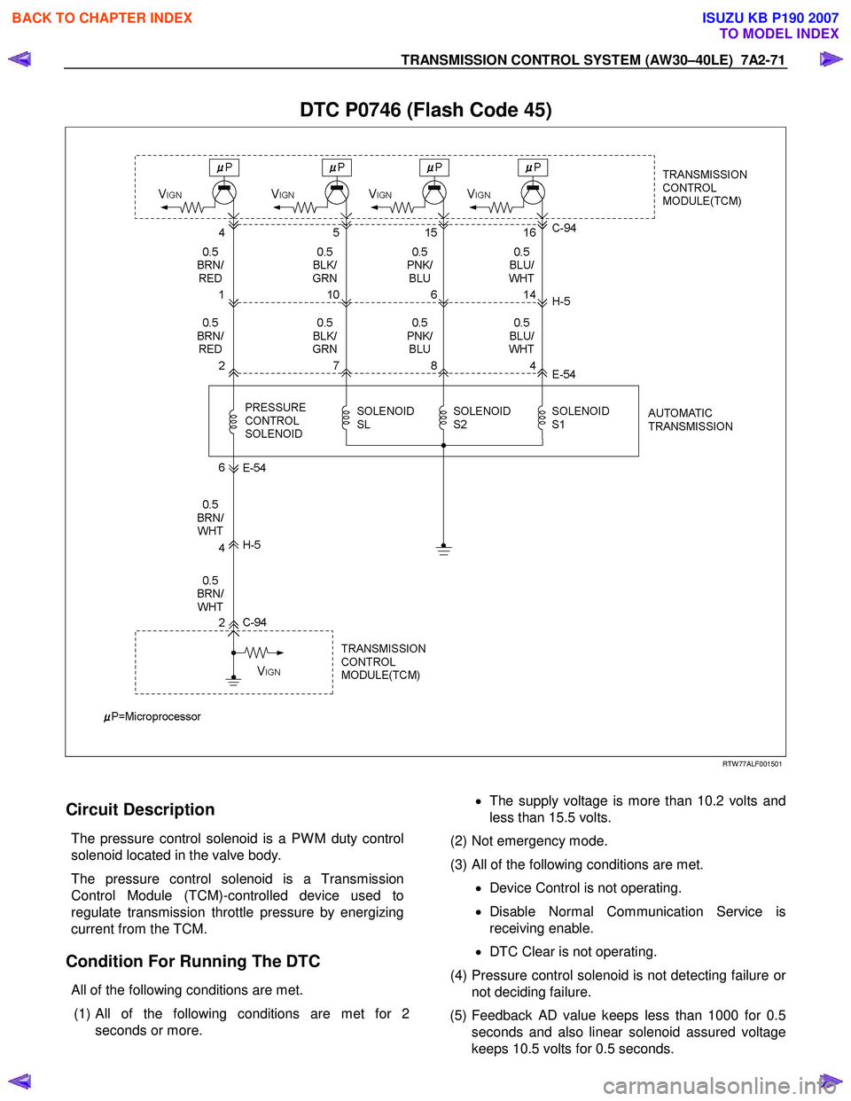
DTC P0746 (Flash Code 45)
RTW 77ALF001501
Circuit Description
The pressure control solenoid is a PW M duty control
solenoid located in the valve body.
The pressure control solenoid is a Transmission
Control Module (TCM)-controlled device used to
regulate transmission throttle pressure by energizing
current from the TCM.
Condition For Running The DTC
All of the following conditions are met.
(1)
All of the following conditions are met for 2
seconds or more.
• The supply voltage is more than 10.2 volts and
less than 15.5 volts.
(2) Not emergency mode.
(3) All of the following conditions are met. • Device Control is not operating.
• Disable Normal Communication Service is
receiving enable.
• DTC Clear is not operating.
(4) Pressure control solenoid is not detecting failure o
r
not deciding failure.
(5) Feedback AD value keeps less than 1000 for 0.5 seconds and also linear solenoid assured voltage
keeps 10.5 volts for 0.5 seconds.
BACK TO CHAPTER INDEX
TO MODEL INDEX
ISUZU KB P190 2007
Page 4040 of 6020

7A2-74 TRANSMISSION CONTROL SYSTEM (AW30–40LE)
DTC P0751 (Flash Code 41)
RTW 77ALF001501
Circuit Description
The shift solenoid S1 changes the hydraulic route with
the signals from the TCM according to the vehicle
speed and the throttle opening to control shifting. W hen
the solenoid S1 or S2 fails, the hydraulic circuit is
mechanically operated as a backup.
Condition For Running The DTC
All of the following conditions are met.
(1)
All of the following conditions are met for 2
seconds or more continuously.
• The supply voltage is more than 10.2 volts and less than 15.5 volts.
• DTC U2104 is not detecting failure or not
deciding failure.
• DTC U2105 is not detecting failure or not deciding failure.
• Engine revolution signal is not detecting failure or not deciding failure.
• The engine revolution is more than 550rpm.
(2) Oil temperature is more than 20 °C (68 °F), and
water temperature signal is more than 70 °C
(158 °F).
(3) 20 seconds or more passed after D position is detected.
(4) Oil temperature sensor is not deciding failure.
BACK TO CHAPTER INDEX
TO MODEL INDEX
ISUZU KB P190 2007
Page 4044 of 6020

7A2-78 TRANSMISSION CONTROL SYSTEM (AW30–40LE)
DTC P0752 (Flash Code 51)
RTW 77ALF001501
Circuit Description
The shift solenoid S1 changes the hydraulic route with
the signals from the TCM according to the vehicle
speed and the throttle opening to control shifting. W hen
the solenoid S1 or S2 fails, the hydraulic circuit is
mechanically operated as a backup.
Condition For Running The DTC
All of the following conditions are met.
(1) All of the following conditions are met for 2 seconds or more continuously.
• The supply voltage is more than 10.2 volts and less than 15.5 volts.
• DTC U2104 is not detecting failure or not
deciding failure.
• DTC U2105 is not detecting failure or not deciding failure.
• Engine revolution signal is not detecting failure or not deciding failure.
• The engine revolution is more than 550 rpm.
(2) Oil temperature is more than 20 °C (68 °F), and
water temperature signal is more than 70 °C
(158 °F).
(3) 20 seconds or more passed after D position is detected.
(4) Oil temperature sensor is not deciding failure.
BACK TO CHAPTER INDEX
TO MODEL INDEX
ISUZU KB P190 2007