alternator ISUZU KB P190 2007 Workshop Owner's Manual
[x] Cancel search | Manufacturer: ISUZU, Model Year: 2007, Model line: KB P190, Model: ISUZU KB P190 2007Pages: 6020, PDF Size: 70.23 MB
Page 3335 of 6020

Engine Management – V6 – Diagnostics Page 6C1-2–57
DTC Description Diagnostic Table
P1629 Immobiliser Fuel Enable Signal Not Received 7.30 DTC P0513, P0633, P1629, P1632,
P1677, P1678 or P1679
P1632 Immobiliser Fuel Disable Signal Received 7.30 DTC P0513, P0633, P1629, P1632,
P1677, P1678 or P1679
P1648 W rong Security Code Entered 7.43 DTC P1648
P1668 Alternator L Terminal Circuit Malfunction 7.44 DTC P1668, P2500 or P2501
P1677 Immobiliser Function not Enabled 7.30 DTC P0513, P0633, P1629, P1632,
P1677, P1678 or P1679
P1678 Engine Control Module Identification Failed 7.30 DTC P0513, P0633, P1629, P1632,
P1677, P1678 or P1679
P1679 Immobiliser Environment Identification Failed 7.30 DTC P0513, P0633, P1629, P1632,
P1677, P1678 or P1679
P1845 Engine Torque Reduction Malfunction 7.45 DTC P1845
P2096 Post Catalyst O2 Sensor Fuel Trim Below Lower Limit
(Bank 1) 7.46 DTC P2096 or P2098
P2097 Post Catalyst O2 Sensor Fuel Trim Above Upper Limit
(Bank 1) 7.47 DTC P2097 or P2099
P2098 Post Catalyst O2 Sensor Fuel Trim Below Lower Limit
(Bank 2) 7.46 DTC P2096 or P2098
P2099 Post Catalyst O2 Sensor Fuel Trim Above Upper Limit
(Bank 2) 7.47 DTC P2097 or P2099
P2100 Throttle Control Motor Malfunction
7.29 DTC P0506, P0507, P0638, P1551,
P2100, P2101, P2119 or P2176
P2101 Throttle Control Position Range / Performance 7.29 DTC P0506, P0507, P0638, P1551,
P2100, P2101, P2119 or P2176
P2105 Throttle Control Forced Engine Shutdown 7.48 DTC P2105
P2107 Throttle Control Malfunction 7.49 DTC P2107
P2119 Closed Throttle Position Range / Performance 7.29 DTC P0506, P0507, P0638, P1551,
P2100, P2101, P2119 or P2176
P2122 Accelerator Pedal Position Sensor 1 Voltage Low 7.50 DTC P2122, P2123, P2127, P2128 or P2138
P2123 Accelerator Pedal Position Sensor 1 Voltage High 7.50 DTC P2122, P2123, P2127, P2128 or P2138
P2127 Accelerator Pedal Position Sensor 2 Voltage Low 7.50 DTC P2122, P2123, P2127, P2128 or P2138
P2128 Accelerator Pedal Position Sensor 2 Voltage High 7.50 DTC P2122, P2123, P2127, P2128 or P2138
P2138 Accelerator Pedal Position Sensor 1-2 Correlation 7.50 DTC P2122, P2123, P2127, P2128 or P2138
P2176 Throttle Control Lower Position not Learned 7.29 DTC P0506, P0507, P0638, P1551,
P2100, P2101, P2119 or P2176
P2177 Fuel Trim Lean during Cruising/Acceleration (Bank 1) 7.51 DTC P2177 or P2179
P2178 Fuel Trim Rich during Cruising/Acceleration (Bank 1) 7.52 DTC P2178 or P2180
P2179 Fuel Trim Lean during Cruising/Acceleration (Bank 2) 7.51 DTC P2177 or P2179
P2180 Fuel Trim Rich during Cruising/Acceleration (Bank 2 7.52 DTC P2178 or P2180
P2187 Fuel Trim Lean during Idling/Deceleration (Bank 1) 7.53 DTC P2187 or P2189
P2188 Fuel Trim Rich during Idling/Deceleration (Bank 1) 7.54 DTC P2188 or P2190
BACK TO CHAPTER INDEX
TO MODEL INDEX
ISUZU KB P190 2007
Page 3338 of 6020

Engine Management – V6 – Diagnostics Page 6C1-2–60
DTC Description Diagnostic Table
P2312 Ignition Coil Cylinder 5 Circuit Low Voltage 7.22 DTC P0351, P0352, P0353, P0354,
P0355, P0356, P2300, P2301, P2303,
P2304, P2306, P2307, P2309, P2310,
P2312, P2313, P2315 or P2316
P2313 Ignition Coil Cylinder 5 Circuit High Voltage 7.22 DTC P0351, P0352, P0353, P0354,
P0355, P0356, P2300, P2301, P2303,
P2304, P2306, P2307, P2309, P2310,
P2312, P2313, P2315 or P2316
P2315 Ignition Coil Cylinder 6 Circuit Low Voltage 7.22 DTC P0351, P0352, P0353, P0354,
P0355, P0356, P2300, P2301, P2303,
P2304, P2306, P2307, P2309, P2310,
P2312, P2313, P2315 or P2316
P2316 Ignition Coil Cylinder 6 Circuit High Voltage 7.22 DTC P0351, P0352, P0353, P0354,
P0355, P0356, P2300, P2301, P2303,
P2304, P2306, P2307, P2309, P2310,
P2312, P2313, P2315 or P2316
P2500 Alternator L Terminal Low Voltage 7.44 DTC P1668, P2500 or P2501
P2501 Alternator L Terminal High Voltage 7.44 DTC P1668, P2500 or P2501
P2626 O2 Sensor Pump Current Trim Circuit Malfunction (Bank 1,
Sensor 1) 7.59 DTC P2237, P2238, P2239, P2240, P2241
or P2242
P2629 O2 Sensor Pump Current Trim Circuit Malfunction (Bank 2, Sensor 1) 7.59 DTC P2237, P2238, P2239, P2240, P2241
or P2242
U0001 No Communication with CAN-Bus (High Speed) 7.61 DTC U0001
U0101 CAN-Bus No Communication W ith TCM (Transmission
Control Module) 7.62 DTC U0101
U0155 CAN-Bus No Communication W ith Gateway
7.63 DTC U0155 or U0423
U0423 CAN-Bus Invalid Data From Gateway 7.63 DTC U0155 or U0423
7.2 DTC P0008, P0009 or P0016
DTC Descriptor
This diagnostic procedure supports the following DTCs:
• DTC P0008 – Engine Position System Performance (Bank 1)
• DTC P0009 – Engine Position System Performance (Bank 2)
• DTC P0016 – Crankshaft / Intake Camshaft Position Not Plausible (Bank 1)
Circuit Description
The engine control relay applies ignition positive battery voltage to the camshaft position (CMP) actuator solenoids
through the ignition voltage circuit.
Using a device called a driver, the ECM applies a pulse width modulated (PW M) ground to the individual CMP solenoid
control circuit. This controls the oil pressure that advances or retards each camshaft position.
The ECM compares the camshaft position to the crankshaft position to detect CMP system malfunction. A CKP / CMP
sensor correlation DTC sets if the ECM detects a deviation between the target position of the camshaft and the
crankshaft position.
Conditions for Running the DTC
DTC P0008 or P0009
Run continuously once the following conditions are met.
BACK TO CHAPTER INDEX
TO MODEL INDEX
ISUZU KB P190 2007
Page 3431 of 6020

Engine Management – V6 – Diagnostics Page 6C1-2–153
Step Action Yes No
When all diagnosis and repairs are completed, check the system for correct operation.
7.36 DTC P0625 or P0626
DTC Descriptors
This diagnostic procedure supports the following DTCs:
• DTC P0625 – Alternator F Terminal Low Voltage
• DTC P0626 – Alternator F Terminal High Voltage
Circuit Description
The voltage regulator within the generator regulates the generator charge output by increasing or decreasing the
generator on time. The generator field (Gen F) duty cycle output signal represents the generator on time. Refer to 6D1-1
Charging System – V6 for details of the charging system operation.
The ECM monitors the Gen F terminal output signal to calculate Gen F duty cycle percentage. This enables the ECM to
provide engine idle compensation based on electrical loads and to detect a fault condition in the generator operation.
A Generator F-terminal circuit DTC sets if the ECM detects the Gen F duty cycle is outside the specified range for a
predetermined set of parameters.
Conditions for Running the DTC
DTC P0625
Runs continuously when the following conditions are met:
• There is no generator, CKP sensor or CMP sensor DTC set.
• The engine speed is less than 3000 rpm
• The generator is not commanded off.
DTC P0626
Runs continuously when the following conditions are met:
• There is no generator, CKP sensor or CMP sensor DTC set.
• The ignition is switched on with the engine not running
Conditions for Setting the DTC
DTC P0625
The ECM detects the Gen F Terminal Signal parameter is less than five percent for 15 seconds.
DTC P0626
The ECM detects the Gen F Terminal Signal parameter is greater than five percent for 15 seconds.
Conditions for Clearing DTC
The Generator F-terminal circuit are Type C DTCs. Refer to 1.4 Diagnostic Trouble Codes in this Section, for action
taken when a Type C DTC sets and conditions for clearing Type C DTCs.
Additional Information
• For an intermittent fault condition, refer to 5.2 Intermittent Fault Conditions in this Section.
• Refer to 6C1-1 Engine Management – V6 – General Information for details of the ECM operation.
BACK TO CHAPTER INDEX
TO MODEL INDEX
ISUZU KB P190 2007
Page 3502 of 6020

Engine Management – V6 – Diagnostics Page 6C1-2–224
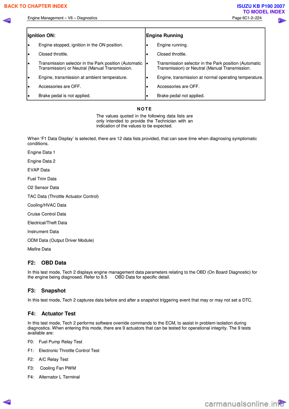
Ignition ON:
• Engine stopped, ignition in the ON position.
• Closed throttle.
• Transmission selector in the Park position (Automatic
Transmission) or Neutral (Manual Transmission.
• Engine, transmission at ambient temperature.
• Accessories are OFF.
• Brake pedal is not applied.
Engine Running
• Engine running.
• Closed throttle.
• Transmission selector in the Park position (Automatic
Transmission) or Neutral (Manual Transmission.
• Engine, transmission at normal operating temperature.
• Accessories are OFF.
• Brake pedal not applied.
NOTE
The values quoted in the following data lists are
only intended to provide the Technician with an
indication of the values to be expected.
W hen ‘F1 Data Display’ is selected, there are 12 data lists provided, that can save time when diagnosing symptomatic
conditions.
Engine Data 1
Engine Data 2
EVAP Data
Fuel Trim Data
O2 Sensor Data
TAC Data (Throttle Actuator Control)
Cooling/HVAC Data
Cruise Control Data
Electrical/Theft Data
Instrument Data
ODM Data (Output Driver Module)
Misfire Data
F2: OBD Data
In this test mode, Tech 2 displays engine management data parameters relating to the OBD (On Board Diagnostic) for
the engine being diagnosed. Refer to 8.5 OBD Data for specific detail.
F3: Snapshot
In this test mode, Tech 2 captures data before and after a snapshot triggering event that may or may not set a DTC.
F4: Actuator Test
In this test mode, Tech 2 performs software override commands to the ECM, to assist in problem isolation during
diagnostics. W hen entering this mode, there are 9 actuators that can be tested for operational integrity. The 9 tests
available are:
F0: Fuel Pump Relay Test
F1: Electronic Throttle Control Test
F2: A/C Relay Test
F3: Cooling Fan PW M
F4: Alternator L Terminal
BACK TO CHAPTER INDEX
TO MODEL INDEX
ISUZU KB P190 2007
Page 3513 of 6020

Engine Management – V6 – Diagnostics Page 6C1-2–235
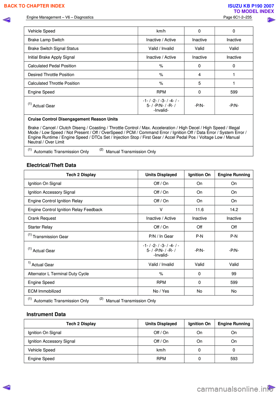
Vehicle Speed km/h 0 0
Brake Lamp Switch Inactive / Active Inactive Inactive
Brake Switch Signal Status Valid / Invalid Valid Valid
Initial Brake Apply Signal Inactive / Active Inactive Inactive
Calculated Pedal Position % 0 0
Desired Throttle Position % 4 1
Calculated Throttle Position % 5 1
Engine Speed RPM 0 599
(1) Actual Gear -1- / -2- / -3- / -4- / -
5- / -P/N- / -R- / -Invalid- -P/N- -P/N-
Cruise Control Disengagement Reason Units
Brake / Cancel / Clutch Diseng / Coasting / Throttle Control / Max. Acceleration / High Decel / High Speed / Illegal
Mode / Low Speed / Not Present / Off / OverSpeed / PCM / Command Error / Ignition Off / Data Error / System Error /
Engine Runtime / Engine Speed / DTCs Set / Injection Stop / First Gear / Accel Pedal Pos / Voltage Low / Manual
Neutral / Over Limit
(1) Automatic Transmission Only (2) Manual Transmission Only
Electrical/Theft Data
Tech 2 Display Units Displayed Ignition On Engine Running
Ignition On Signal Off / On On On
Ignition Accessory Signal Off / On On On
Engine Control Ignition Relay Off / On On On
Engine Control Ignition Relay Feedback V 11.6 14.2
Crank Request Inactive / Active Inactive Inactive
Starter Relay Off / On Off Off
(1) Transmission Gear P/N / In Gear P-N P-N
(1) Actual Gear -1- / -2- / -3- / -4- / -
5- / -P/N- / -R- / -Invalid- -P/N- -P/N-
1) Actual Gear
Valid / Invalid Valid
Valid
Alternator L Terminal Duty Cycle % 0 99
Engine Speed RPM 0 599
ECM Immobilized No / Yes No No
(1) Automatic Transmission Only (2) Manual Transmission Only
Instrument Data
Tech 2 Display Units Displayed Ignition On Engine Running
Ignition On Signal Off / On On On
Ignition Accessory Signal Off / On On On
Vehicle Speed km/h 0 0
Engine Speed RPM 0 593
BACK TO CHAPTER INDEX
TO MODEL INDEX
ISUZU KB P190 2007
Page 3516 of 6020

Engine Management – V6 – Diagnostics Page 6C1-2–238
B2 Average Injection Time (Bank 2) ms 0.0 1.9
Mass Air Flow Sensor V 1.0 1.1
Mass Air Flow g/s 0.00 2.92
Power Enrichment No / Yes No No
Spark Advance °CA 0 13
Calculated Throttle Position % 5 1
Vehicle Speed km/h 0 0
Volumetric Efficiency % 99 13
(1) Automatic Transmission Only (2) Manual Transmission Only
8.4 Tech 2 Data Definitions
NOTE
This listing is arranged in alphabetical order and
defines each parameter shown in the Data Lists.
A/C Cutoff Mode (Air Conditioning): This parameter displays whether the control module is commanding the A/C
compressor clutch relay OFF for a number of reasons, among which is; operating pressure outside given parameters or
throttle position at wide open throttle (W OT).
A/C Disengagement 1 – 8 History: The parameter displays the last 8 air conditioning (A/C) compressor disengages in
order from 1 to 8 with 8 being the most recent. There are 8 possible causes listed for the A/C compressor to disengage;
High Pressure, Engine Speed, Battery Voltage, Stall Prevention, Full Load, Performance, Engine Temperature or Signal
not Present. Any of these causes need to be outside calibrated values, to cause the A/C to disengage.
A/C Pressure Sensor (Air Conditioning): This parameter displays the voltage from the A/C high side pressure sensor
signal circuit to the control module.
A/C Pressure Sensor (Air Conditioning): This parameter displays the pressure in kPa from the A/C high side pressure
sensor signal circuit to the control module.
A/C Relay (Air Conditioning): This parameter displays the state of the A/C clutch relay control circuit, either as ‘ON’ or
‘OFF’.
A/C Relay Status: This parameter displays the state of the A/C request input to the control module from the heating,
ventilation, and air conditioning (HVAC) controls.
A/C Request: Represents the commanded state of the A/C clutch control relay. Clutch should be engaged when ON is
displayed.
Actual Gear: This parameter displays the transmission range input to the control module, determined directly from the
decoding of the PRNDL – A, B, C, and P inputs from the transmission internal mode switch (IMS).
Actual Gear: Based on the evaluation of the PRNDL – A, B, C, and P inputs, the ECM determines whether the
parameter is valid or invalid.
Actual Intake Camshaft Position (Bank 1 or Bank 2): This parameter displays the actual intake camshaft position in
degrees of crankshaft angle.
Alternator L Terminal Duty Cycle: This parameter displays the ECM commanded state of the voltage regulator on the
alternator, expressed as a percentage from 0 to 100.
APP Sensor 1 (Accelerator Pedal Position): This parameter displays the actual voltage on the APP sensor 1 signal
circuit as measured by the ECM, that can range from 0.9 – 4.5 volts.
APP Sensor 2 (Accelerator Pedal Position): This parameter displays the actual voltage on the APP sensor 1 signal
circuit as measured by the ECM, that can range from 0.45 – 2.25 volts.
APP Sensor 1 and 2 Correlation (Accelerator Pedal Position): This parameter displays ‘Okay’ under normal
operating conditions or ‘Fault’ if the control module detects the signal voltage from APP sensor 1 that is not in the
correct relationship to APP sensor 2.
Average Injection Time (Bank 1 or Bank 2): This parameter displays the average pulse width of the fuel injectors for
each bank of the engine as determined by the ECM.
BACK TO CHAPTER INDEX
TO MODEL INDEX
ISUZU KB P190 2007
Page 3522 of 6020

Engine Management – V6 – Diagnostics Page 6C1-2–244
Precondition: Ignition ‘On’.
Cooling Fan (PWM)
Take care that no-one can access the engine
compartment during these tests!
This test allows the Technician to turn the cooling fan on in increments to its maximum speed.
Precondition: Ignition ‘On’ Air conditioning is ‘Off’..
Alternator L Terminal
This test allows the Technician to turn ‘On’ and ‘Off’, the commanded state of the voltage regulator in the alternator. ‘On’
displays a commanded state of 99%, while ‘Off’ displays a commanded state of 0%.
Precondition: Engine running.
EVAP Purge Solenoid
This test allows the Technician to control the EVAP purge solenoid valve. The normal commanded state is ‘0%’. The
system will increase or decrease the amount of purge by changing the duty cycle of the purge valve in 10% increments
within a range of 0 – 100%. The system will remain in the commanded state until cancelled by Tech 2.
NOTE
The EVAP Purge Solenoid Command parameter
may not change states when using this output
control.
Precondition: Ignition ‘On’, engine ‘Off’.
Engine Speed Control
Other DTCs may set when the Engine Speed
Control function is used. Disregard those
DTCs that set under this condition.
Allows the increase / decrease of the engine speed in 20 – 30 rpm increments from the base idle speed, up to 1,600
rpm.
NOTE
If the engine coolant temperature is below the
prescribed minimum, a message to that effect is
displayed and access to engine speed control is
blocked.
Preconditions: Engine running, engine temperature above 80 °C, transmission in Park or Neutral.
BACK TO CHAPTER INDEX
TO MODEL INDEX
ISUZU KB P190 2007
Page 3588 of 6020

Charging System – V6 Page 6D1-1-1
6D1-1
Charging System – V6
ATTENTION
Before performing any service operations or other procedure described in this Section, refer to
1.2 WARNING, CAUTION and NOTES for correct workshop practices with regard to safety and / or
property damage.
1 General Information ............................................................................................................ ...................3
1.1 Components ........................................................................................................................................................... 3
Generator................................................................................................................................................................ 3
Generator Types ................................................................................................................................................ 3
Voltage Regulator .................................................................................................................................................. 4
1.2 WARNING, CAUTION and NOTES..................................................................................................... .................... 4
Definition of WARNING, CAUTION and NOTE Statements............................................................................. .... 4
W ARNING defined ............................................................................................................................................. 4
CAUTION defined .............................................................................................................................................. 5
NOTE defined .................................................................................................................................................... 5
1.3 System Operation .................................................................................................................................................. 5
Operation ........................................................................................................................................................... 5
Alternator W arning ............................................................................................................. ................................ 6
2 Diagnosis ................................................................................................................................................7
2.1 Diagnostic General Information ........................................................................................................................... 7
Basic Diagnostic Tools Required ................................................................................................ ......................... 7
2.2 Tech 2 Data List ..................................................................................................................................................... 7
2.3 Diagnostic Systems Check ....................................................................................................... ............................ 7
2.4 Wiring Diagram ...................................................................................................................................................... 8
2.5 Charging System Inoperative / Malfunctioning ................................................................................................... 9
Diagnostic Table Notes ......................................................................................................... ............................. 9
Diagnostic Table 120A Generator ................................................................................................ ...................... 9
3 Minor Service Operations ....................................................................................................................10
3.1 Safety Precautions............................................................................................................................................... 10
3.2 Maintenance ......................................................................................................................................................... 10
Regular Checks................................................................................................................. ................................... 10
Lubrication ....................................................................................................................................................... 10
3.3 On-vehicle Testing ............................................................................................................. .................................. 11
Generator On-vehicle Checks.................................................................................................... ......................... 11
Prerequisites .................................................................................................................................................... 11
Generator Test ................................................................................................................................................. 11
Charging Circuit Voltage Drop Test ............................................................................................. ...................... 13
Prerequisites .................................................................................................................................................... 13
Voltage Drop Test ............................................................................................................................................ 13
4 Major Service Operations ....................................................................................................................15
4.1 Generator.............................................................................................................................................................. 15
Remove ................................................................................................................................................................. 15
Reinstall ................................................................................................................................................................ 16
4.2 Generator Mounting Bracket ..................................................................................................... ......................... 17
Remove ................................................................................................................................................................. 17
Reinstall ................................................................................................................................................................ 17
BACK TO CHAPTER INDEX
TO MODEL INDEX
ISUZU KB P190 2007
Page 3593 of 6020

Charging System – V6 Page 6D1-1-6
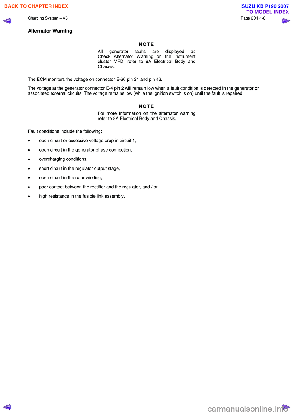
Alternator Warning
NOTE
All generator faults are displayed as
Check Alternator W arning on the instrument
cluster MFD, refer to 8A Electrical Body and
Chassis.
The ECM monitors the voltage on connector E-60 pin 21 and pin 43.
The voltage at the generator connector E-4 pin 2 will remain low when a fault condition is detected in the generator or
associated external circuits. The voltage remains low (while the ignition switch is on) until the fault is repaired.
NOTE
For more information on the alternator warning
refer to 8A Electrical Body and Chassis.
Fault conditions include the following:
• open circuit or excessive voltage drop in circuit 1,
• open circuit in the generator phase connection,
• overcharging conditions,
• short circuit in the regulator output stage,
• open circuit in the rotor winding,
• poor contact between the rectifier and the regulator, and / or
• high resistance in the fusible link assembly.
BACK TO CHAPTER INDEX
TO MODEL INDEX
ISUZU KB P190 2007
Page 3594 of 6020

Charging System – V6 Page 6D1-1-7
2 Diagnosis
2.1 Diagnostic General Information
Basic Diagnostic Tools Required
Use of incorrect electrical circuit diagnostic
tools when performing the generator
diagnostic procedures could result in
incorrect diagnostic results or damage to
components.
The following electrical circuit testing tools are required to perform the diagnostic procedures detailed in this Section:
• digital multimeter with 10 mega ohms impedance, and
• connector test adapter kit Tool No. KM609.
For further information on the use of these tools, refer to 8A Electrical Body and Chassis.
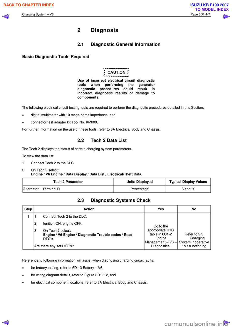
2.2 Tech 2 Data List
The Tech 2 displays the status of certain charging system parameters.
To view the data list:
1 Connect Tech 2 to the DLC.
2 On Tech 2 select: Engine / V6 Engine / Data Display / Data List / Electrical/Theft Data .
Tech 2 Parameter Units Displayed Typical Display Values
Alternator L Terminal D Percentage Various
2.3 Diagnostic Systems Check
Step Action Yes No
1 1 Connect Tech 2 to the DLC.
2 Ignition ON, engine OFF.
3 On Tech 2 select: Engine / V6 Engine / Diagnostic Trouble codes / Read
DTC’s.
Are there any set DTC’s? Go to the
appropriate DTC table in 6C1-2 Engine
Management – V6 – Diagnostics. Refer to 2.5
Charging
System Inoperative / Malfunctioning
Reference to following information will assist when diagnosing charging circuit faults:
• for battery testing, refer to 6D1-3 Battery – V6,
• for wiring diagram details, refer to Figure 6D1-1 2, and
• for electrical component locations, refer to 8A Electrical Body and Chassis.
BACK TO CHAPTER INDEX
TO MODEL INDEX
ISUZU KB P190 2007