spark plugs replace ISUZU KB P190 2007 Workshop Repair Manual
[x] Cancel search | Manufacturer: ISUZU, Model Year: 2007, Model line: KB P190, Model: ISUZU KB P190 2007Pages: 6020, PDF Size: 70.23 MB
Page 20 of 6020
0B-2 MAINTENANCE AND LUBRICATION
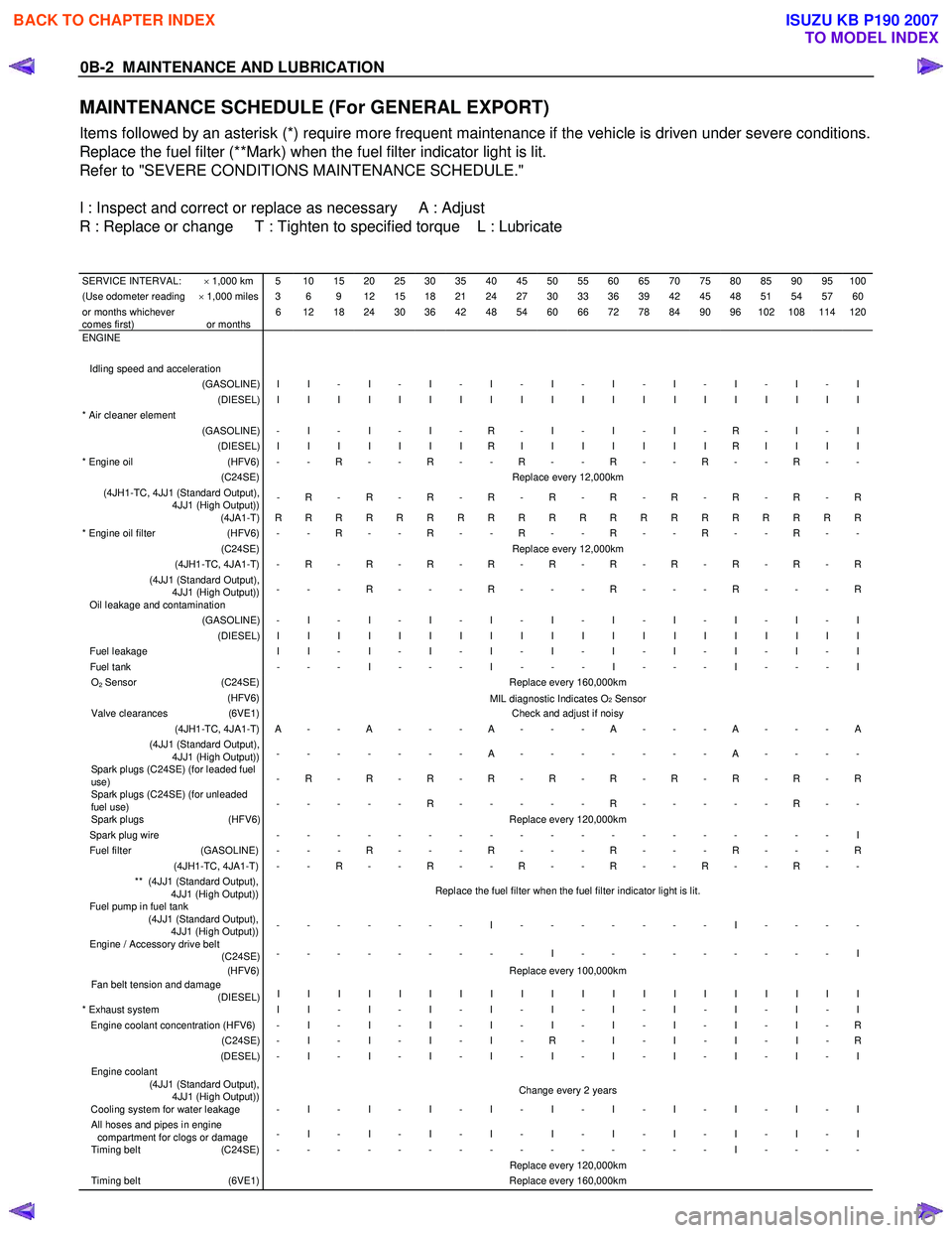
MAINTENANCE SCHEDULE (For GENERAL EXPORT)
Items followed by an asterisk (*) require more frequent maintenance if the vehicle is driven under severe conditions.
Replace the fuel filter (**Mark) when the fuel filter indicator light is lit.
Refer to "SEVERE CONDITIONS MAINTENANCE SCHEDULE."
I : Inspect and correct or replace as necessary A : Adjust
R : Replace or change T : Tighten to specified torque L : Lubricate
SERVICE INTERVAL: × 1,000 km 5 10 15 20 25 30 35 40 45 50 55 60 65 70 75 80 85 90 95 100(Use odometer reading × 1,000 miles 3 6 9 12 15 18 21 24 27 30 33 36 39 42 45 48 51 54 57 60or months whichever
comes first)
or months 6 12 18 24 30 36 42 48 54 60 66 72 78 84 90 96 102 108 114 120
ENGINE
Idling speed and acceleration
(GASOLINE) I I - I - I - I - I - I - I - I - I - I (DIESEL) I I I I I I I I I I I I I I I I I I I I * Air cleaner element
(GASOLINE) - I - I - I - R - I - I - I - R - I - I (DIESEL) I I I I I I I R I I I I I I I R I I I I * Engine oil (HFV6) - - R - - R - - R - - R - - R - - R - - (C24SE) Replace every 12,000km (4JH1-TC, 4JJ1 (Standard Output),
4JJ1 (High Output)) - R - R - R - R - R - R - R - R - R - R
(4JA1-T) R R R R R R R R R R R R R R R R R R R R * Engine oil filter (HFV6) - - R - - R - - R - - R - - R - - R - - (C24SE) Replace every 12,000km (4JH1-TC, 4JA1-T) - R - R - R - R - R - R - R - R - R - R (4JJ1 (Standard Output),
4JJ1 (High Output)) - - - R - - - R - - - R - - - R - - - R
Oil leakage and contamination (GASOLINE) - I - I - I - I - I - I - I - I - I - I (DIESEL) I I I I I I I I I I I I I I I I I I I I Fuel leakage
I I - I - I - I - I - I - I - I - I - I Fuel tank - - - I - - - I - - - I - - - I - - - I O2 Sensor (C24SE) Replace every 160,000km (HFV6)
MIL diagnostic Indicates O2 Sensor Valve clearances (6VE1) Check and adjust if noisy (4JH1-TC, 4JA1-T) A - - A - - - A - - - A - - - A - - - A (4JJ1 (Standard Output),
4JJ1 (High Output)) - - - - - - - A - - - - - - - A - - - -
Spark plugs (C24SE) (for leaded fuel
use) - R - R - R - R - R - R - R - R - R - R
Spark plugs (C24SE) (for unleaded
fuel use) - - - - - R - - - - - R - - - - - R - -
Spark plugs
(HFV6) Replace every 120,000km Spark plug wire - - - - - - - - - - - - - - - - - - - I Fuel filter (GASOLINE) - - - R - - - R - - - R - - - R - - - R (4JH1-TC, 4JA1-T) - - R - - R - - R - - R - - R - - R - - ** (4JJ1 (Standard Output),
4JJ1 (High Output)) Replace the fuel filter when the fuel filter indicator light is lit.
Fuel pump in fuel tank
(4JJ1 (Standard Output),
4JJ1 (High Output)) - - - - - - - I - - - - - - - I - - - -
Engine / Accessory drive belt
(C24SE) - - - - - - - - - I - - - - - - - - - I
(HFV6) Replace every 100,000km Fan belt tension and damage
(DIESEL) I I I I I I I I I I I I I I I I I I I I
* Exhaust system
I I - I - I - I - I - I - I - I - I - I Engine coolant concentration (HFV6) - I - I - I - I - I - I - I - I - I - R (C24SE) - I - I - I - I - R - I - I - I - I - R (DESEL) - I - I - I - I - I - I - I - I - I - I Engine coolant
(4JJ1 (Standard Output),
4JJ1 (High Output)) Change every 2 years
Cooling system for water leakage - I - I - I - I - I - I - I - I - I - I All hoses and pipes in engine
compartment for clogs or damage - I - I - I - I - I - I - I - I - I - I
Timing belt
(C24SE) - - - - - - - - - - - - - - - I - - - - Replace every 120,000km Timing belt (6VE1) Replace every 160,000km
BACK TO CHAPTER INDEX
TO MODEL INDEX
ISUZU KB P190 2007
Page 2003 of 6020
ENGINE DIAGNOSIS (C24SE) 6-3
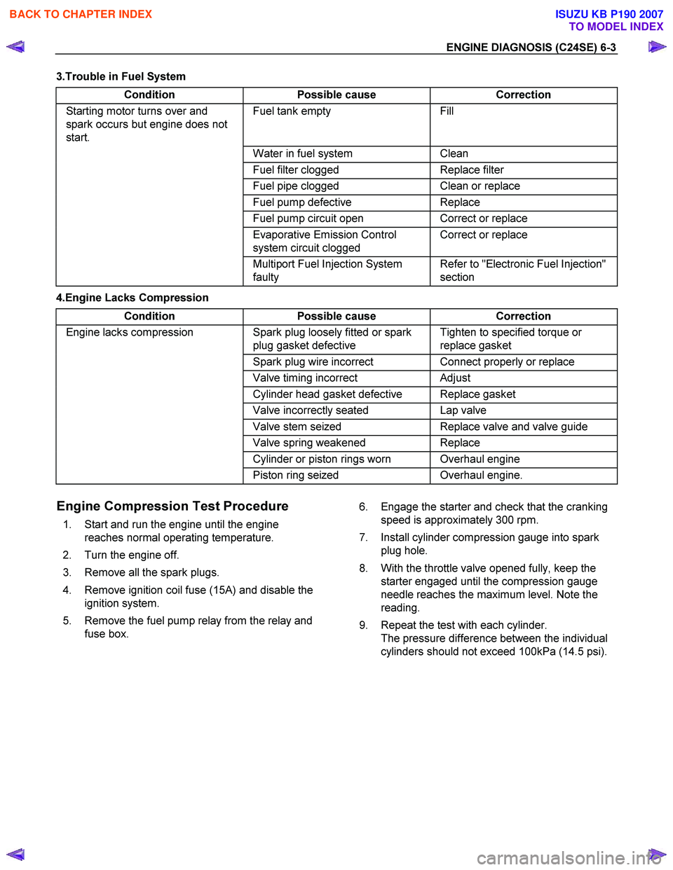
3.Trouble in Fuel System Condition Possible cause Correction
Starting motor turns over and
spark occurs but engine does not
start. Fuel tank empty Fill
Water in fuel system Clean
Fuel filter clogged Replace filter
Fuel pipe clogged Clean or replace
Fuel pump defective Replace
Fuel pump circuit open Correct or replace
Evaporative Emission Control
system circuit clogged Correct or replace
Multiport Fuel Injection System
faulty Refer to "Electronic Fuel Injection"
section
4.Engine Lacks Compression
Condition Possible cause Correction
Engine lacks compression Spark plug loosely fitted or spark
plug gasket defective Tighten to specified torque or
replace gasket
Spark plug wire incorrect Connect properly or replace
Valve timing incorrect Adjust
Cylinder head gasket defective Replace gasket
Valve incorrectly seated Lap valve
Valve stem seized Replace valve and valve guide
Valve spring weakened Replace
Cylinder or piston rings worn Overhaul engine
Piston ring seized Overhaul engine.
Engine Compression Test Procedure
1. Start and run the engine until the engine
reaches normal operating temperature.
2. Turn the engine off.
3. Remove all the spark plugs.
4. Remove ignition coil fuse (15A) and disable the ignition system.
5. Remove the fuel pump relay from the relay and fuse box. 6. Engage the starter and check that the cranking
speed is approximately 300 rpm.
7. Install cylinder compression gauge into spark plug hole.
8. With the throttle valve opened fully, keep the starter engaged until the compression gauge
needle reaches the maximum level. Note the
reading.
9. Repeat the test with each cylinder. The pressure difference between the individual
cylinders should not exceed 100kPa (14.5 psi).
BACK TO CHAPTER INDEX
TO MODEL INDEX
ISUZU KB P190 2007
Page 2005 of 6020
ENGINE DIAGNOSIS (C24SE) 6-5
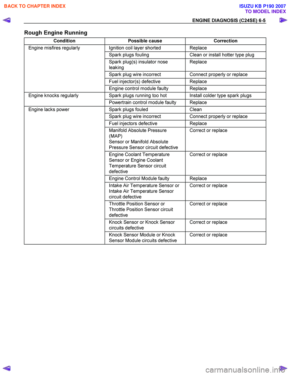
Rough Engine Running
Condition Possible cause Correction
Engine misfires regularly Ignition coil layer shorted Replace
Spark plugs fouling Clean or install hotter type plug
Spark plug(s) insulator nose
leaking Replace
Spark plug wire incorrect Connect properly or replace
Fuel injector(s) defective Replace
Engine control module faulty Replace
Engine knocks regularly Spark plugs running too hot Install colder type spark plugs
Powertrain control module faulty Replace
Engine lacks power Spark plugs fouled Clean
Spark plug wire incorrect Connect properly or replace
Fuel injectors defective Replace
Manifold Absolute Pressure
(MAP)
Sensor or Manifold Absolute
Pressure Sensor circuit defective Correct or replace
Engine Coolant Temperature
Sensor or Engine Coolant
Temperature Sensor circuit
defective Correct or replace
Engine Control Module faulty Replace
Intake Air Temperature Sensor or
Intake Air Temperature Sensor
circuit defective Correct or replace
Throttle Position Sensor or
Throttle Position Sensor circuit
defective Correct or replace
Knock Sensor or Knock Sensor
circuits defective Correct or replace
Knock Sensor Module or Knock
Sensor Module circuits defective Correct or replace
BACK TO CHAPTER INDEX
TO MODEL INDEX
ISUZU KB P190 2007
Page 2007 of 6020
ENGINE DIAGNOSIS (C24SE) 6-7
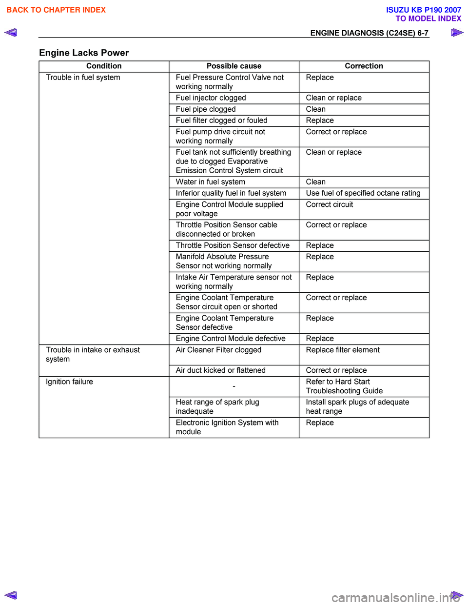
Engine Lacks Power
Condition Possible cause Correction
Trouble in fuel system Fuel Pressure Control Valve not
working normally Replace
Fuel injector clogged Clean or replace
Fuel pipe clogged Clean
Fuel filter clogged or fouled Replace
Fuel pump drive circuit not
working normally Correct or replace
Fuel tank not sufficiently breathing
due to clogged Evaporative
Emission Control System circuit Clean or replace
Water in fuel system Clean
Inferior quality fuel in fuel system Use fuel of specified octane rating
Engine Control Module supplied
poor voltage Correct circuit
Throttle Position Sensor cable
disconnected or broken Correct or replace
Throttle Position Sensor defective Replace
Manifold Absolute Pressure
Sensor not working normally Replace
Intake Air Temperature sensor not
working normally Replace
Engine Coolant Temperature
Sensor circuit open or shorted Correct or replace
Engine Coolant Temperature
Sensor defective Replace
Engine Control Module defective Replace
Trouble in intake or exhaust
system Air Cleaner Filter clogged Replace filter element
Air duct kicked or flattened Correct or replace
Ignition failure
- Refer to Hard Start
Troubleshooting Guide
Heat range of spark plug
inadequate Install spark plugs of adequate
heat range
Electronic Ignition System with
module Replace
BACK TO CHAPTER INDEX
TO MODEL INDEX
ISUZU KB P190 2007
Page 2010 of 6020
6-10 ENGINE DIAGNOSIS (C24SE)
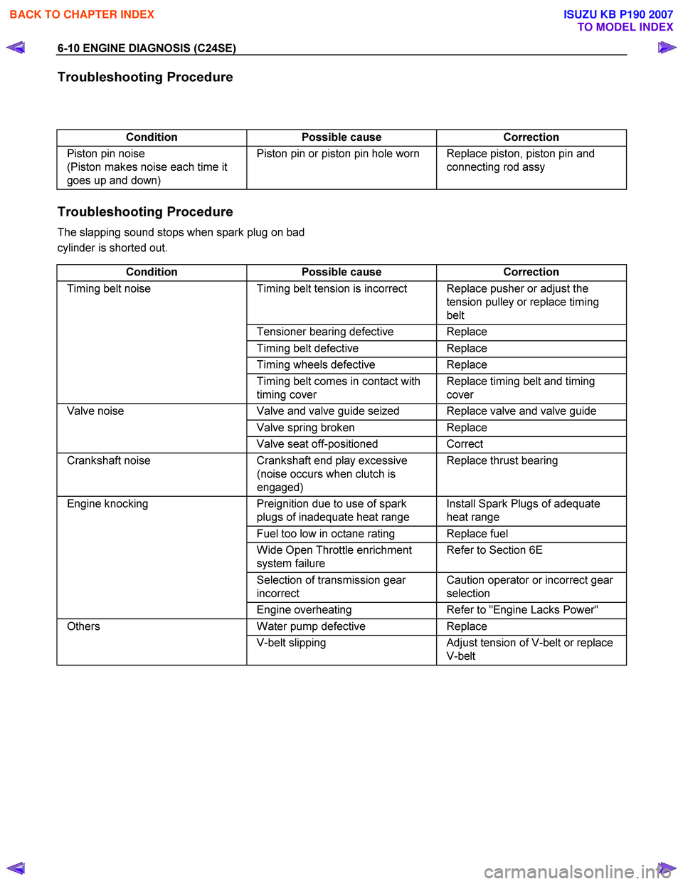
Troubleshooting Procedure
Condition Possible cause Correction
Piston pin noise
(Piston makes noise each time it
goes up and down) Piston pin or piston pin hole worn Replace piston, piston pin and
connecting rod assy
Troubleshooting Procedure
The slapping sound stops when spark plug on bad
cylinder is shorted out.
Condition Possible cause Correction
Timing belt noise Timing belt tension is incorrect Replace pusher or adjust the
tension pulley or replace timing
belt
Tensioner bearing defective Replace
Timing belt defective Replace
Timing wheels defective Replace
Timing belt comes in contact with
timing cover Replace timing belt and timing
cover
Valve noise Valve and valve guide seized Replace valve and valve guide
Valve spring broken Replace
Valve seat off-positioned Correct
Crankshaft noise Crankshaft end play excessive
(noise occurs when clutch is
engaged) Replace thrust bearing
Engine knocking
Preignition due to use of spark
plugs of inadequate heat range Install Spark Plugs of adequate
heat range
Fuel too low in octane rating Replace fuel
Wide Open Throttle enrichment
system failure Refer to Section 6E
Selection of transmission gear
incorrect Caution operator or incorrect gear
selection
Engine overheating Refer to "Engine Lacks Power"
Others Water pump defective Replace
V-belt slipping Adjust tension of V-belt or replace
V-belt
BACK TO CHAPTER INDEX
TO MODEL INDEX
ISUZU KB P190 2007
Page 2027 of 6020
ENGINE MECHANICAL (C24SE) 6A-13
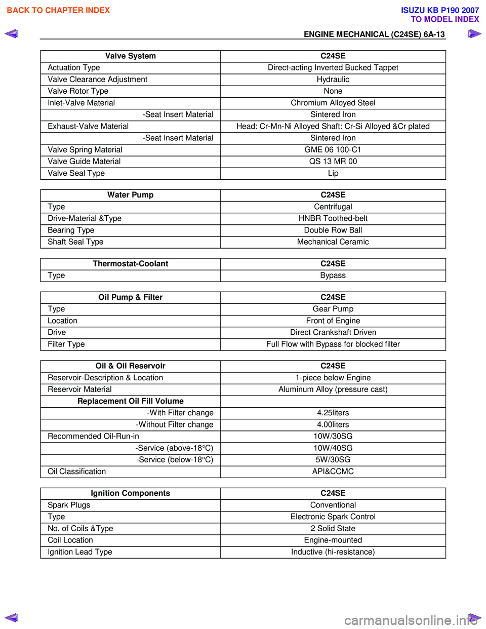
Valve System C24SE
Actuation Type Direct-acting Inverted Bucked Tappet
Valve Clearance Adjustment Hydraulic
Valve Rotor Type None
Inlet-Valve Material Chromium Alloyed Steel
-Seat Insert MaterialSintered Iron
Exhaust-Valve Material Head: Cr-Mn-Ni Alloyed Shaft: Cr-Si Alloyed &Cr plated
-Seat Insert MaterialSintered Iron
Valve Spring Material GME 06 100-C1
Valve Guide Material QS 13 MR 00
Valve Seal Type Lip
Water Pump C24SE
Type Centrifugal
Drive-Material &Type HNBR Toothed-belt
Bearing Type Double Row Ball
Shaft Seal Type Mechanical Ceramic
Thermostat-Coolant C24SE
Type Bypass
Oil Pump & Filter C24SE
Type Gear Pump
Location Front of Engine
Drive Direct Crankshaft Driven
Filter Type Full Flow with Bypass for blocked filter
Oil & Oil Reservoir C24SE
Reservoir-Description & Location 1-piece below Engine
Reservoir Material Aluminum Alloy (pressure cast)
Replacement Oil Fill Volume
-W ith Filter change4.25liters
-W ithout Filter change 4.00liters
Recommended Oil-Run-in 10W /30SG
-Service (above-18°C) 10W /40SG
-Service (below-18°C) 5W /30SG
Oil Classification API&CCMC
Ignition Components C24SE
Spark Plugs Conventional
Type Electronic Spark Control
No. of Coils &Type 2 Solid State
Coil Location Engine-mounted
Ignition Lead Type Inductive (hi-resistance)
BACK TO CHAPTER INDEX
TO MODEL INDEX
ISUZU KB P190 2007
Page 2051 of 6020
ENGINE MECHANICAL (C24SE) 6A-37
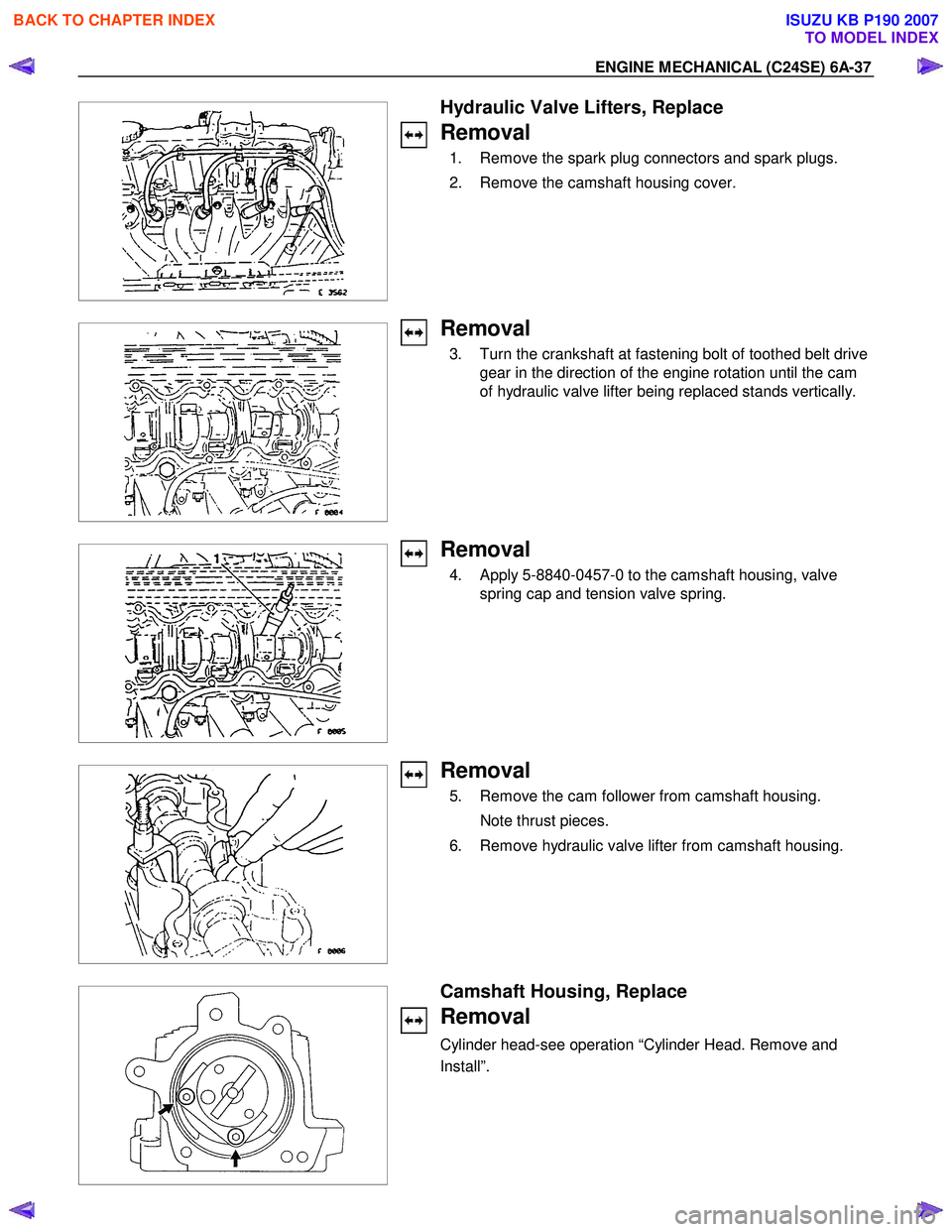
Hydraulic Valve Lifters, Replace
Removal
1. Remove the spark plug connectors and spark plugs.
2. Remove the camshaft housing cover.
Removal
3. Turn the crankshaft at fastening bolt of toothed belt drive gear in the direction of the engine rotation until the cam
of hydraulic valve lifter being replaced stands vertically.
Removal
4. Apply 5-8840-0457-0 to the camshaft housing, valve spring cap and tension valve spring.
Removal
5. Remove the cam follower from camshaft housing.
Note thrust pieces.
6. Remove hydraulic valve lifter from camshaft housing.
Camshaft Housing, Replace
Removal
Cylinder head-see operation “Cylinder Head. Remove and
Install”.
BACK TO CHAPTER INDEX
TO MODEL INDEX
ISUZU KB P190 2007
Page 2146 of 6020
IGNITION SYSTEM 6D2-3
Spark Plug
Removal
1. Remove spark plugs.
Inspection and Repair
The spark plug affects entire engine performance and
therefore its inspection is very important.
• Check electrode and insulator for presence of cracks, and
replace if any.
• Check electrode for wear, and replace if necessary.
• Check gasket for damage, and replace if necessary.
• Measure insulation resistance with an ohmmeter, and
replace if faulty.
• Adjust spark plug gap to 1.0 - 1.1 mm (0.027 in) - 0.8 mm
(0.031 in).
• Check fuel and electrical systems if spark plug is extremely
dirty.
• Use spark plugs having low heat value (hot type plug) if fuel
and electrical systems are normal.
• Use spark plugs having high heat value (cold type plug) i
f
insulator and electrode are extremely burned.
Sooty Spark Plugs
Much deposit of carbon or oil on the electrode and insulator of
spark plug reduces the engine performance.
Possible causes:
• Too rich mixture
• Presence of oil in combustion chamber
• Incorrectly adjusted spark plug gap
Burning Electrodes
This fault is characterized by scorched or heavily oxidized
electrode or blistered insulator nose.
Possible causes:
• Too lean mixture
• Improper heat value
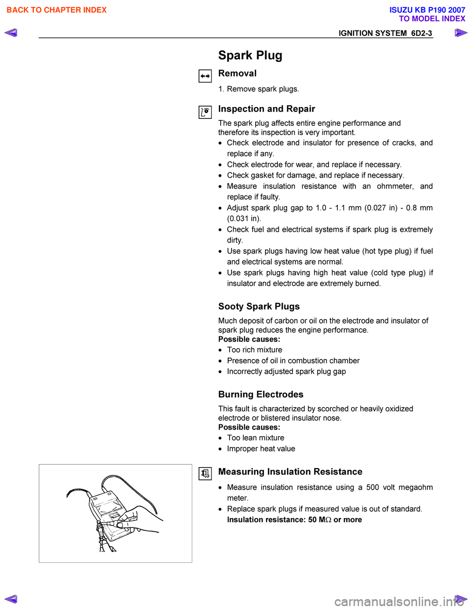
Measuring Insulation Resistance
• Measure insulation resistance using a 500 volt megaohm
meter.
• Replace spark plugs if measured value is out of standard.
Insulation resistance: 50 M Ω or more
BACK TO CHAPTER INDEX
TO MODEL INDEX
ISUZU KB P190 2007
Page 2224 of 6020
6E–54 ENGINE DRIVEABILITY AND EMISSIONS
GENERAL DESCRIPTION FOR ELECTRIC
IGNITION SYSTEM
The engine use two ignition coils, one per two cylinders.
A two wire connector provides a battery voltage primary
supply through the ignition fuse.
The ignition control spark timing is the ECM’s method of
controlling the spark advance and the ignition dwell.
The ignition control spark advance and the ignition dwell
are calculated by the ECM using the following inputs.
• Engine speed
• Crankshaft position (CKP) sensor
• Engine coolant temperature (ECT) sensor
• Throttle position sensor
• Vehicle speed sensor
• ECM and ignition system supply voltage
Ignition coil works to generate only the secondary
voltage be receiving the primary voltage from ECM.
The primary voltage is generated at the coil driver
located in the ECM. The coil driver generate the primary
voltage based on the crankshaft position signal. In
accordance with the crankshaft position signal, ignition
coil driver determines the adequate ignition timing and
also cylinder number to ignite.
Ignition timing is determined the coolant temperature,
intake air temperature, engine speed, engine load,
knock sensor signal, etc.
Spark Plug
Although worn or dirty spark plugs may give satisfactory
operation at idling speed, they frequently fail at higher
engine speeds. Faulty spark plugs may cause poor fuel
economy, power loss, loss of speed, hard starting and
generally poor engine performance. Follow the
scheduled maintenance service recommendations to
ensure satisfactory spark plug performance. Refer to
Maintenance and Lubrication .
Normal spark plug operation will result in brown to
grayish-tan deposits appearing on the insulator portion
of the spark plug. A small amount of red-brown, yellow,
and white powdery material may also be present on the
insulator tip around the center electrode. These
deposits are normal combustion by-products of fuels
and lubricating oils with additives. Some electrode wear
will also occur. Engines which are not running properly
are often referred to as “misfiring.” This means the
ignition spark is not igniting the air/fuel mixture at the
proper time. While other ignition and fuel system causes
must also be considered, possible causes include
ignition system conditions which allow the spark voltage
to reach ground in some other manner than by jumping
across the air gap at the tip of the spark plug, leaving
the air/fuel mixture unburned. Misfiring may also occur
when the tip of the spark plug becomes overheated and
ignites the mixture before the spark jumps. This is
referred to as “pre-ignition.”
Spark plugs may also misfire due to fouling, excessive
gap, or a cracked or broken insulator. If misfiring occurs before the recommended replacement interval, locate
and correct the cause.
Carbon fouling of the spark plug is indicated by dry,
black carbon (soot) deposits on the portion of the spark
plug in the cylinder. Excessive idling and slow speeds
under light engine loads can keep the spark plug
temperatures so low that these deposits are not burned
off. Very rich fuel mixtures or poor ignition system output
may also be the cause. Refer to DTC P1167.
Oil fouling of the spark plug is indicated by wet oily
deposits on the portion of the spark plug in the cylinder,
usually with little electrode wear. This may be caused by
oil during break-in of new or newly overhauled engines.
Deposit fouling of the spark plug occurs when the
normal red-brown, yellow or white deposits of
combustion by-products become sufficient to cause
misfiring. In some cases, these deposits may melt and
form a shiny glaze on the insulator around the center
electrode. If the fouling is found in only one or two
cylinders, valve stem clearances or intake valve seals
may be allowing excess lubricating oil to enter the
cylinder, particularly if the deposits are heavier on the
side of the spark plug facing the intake valve.
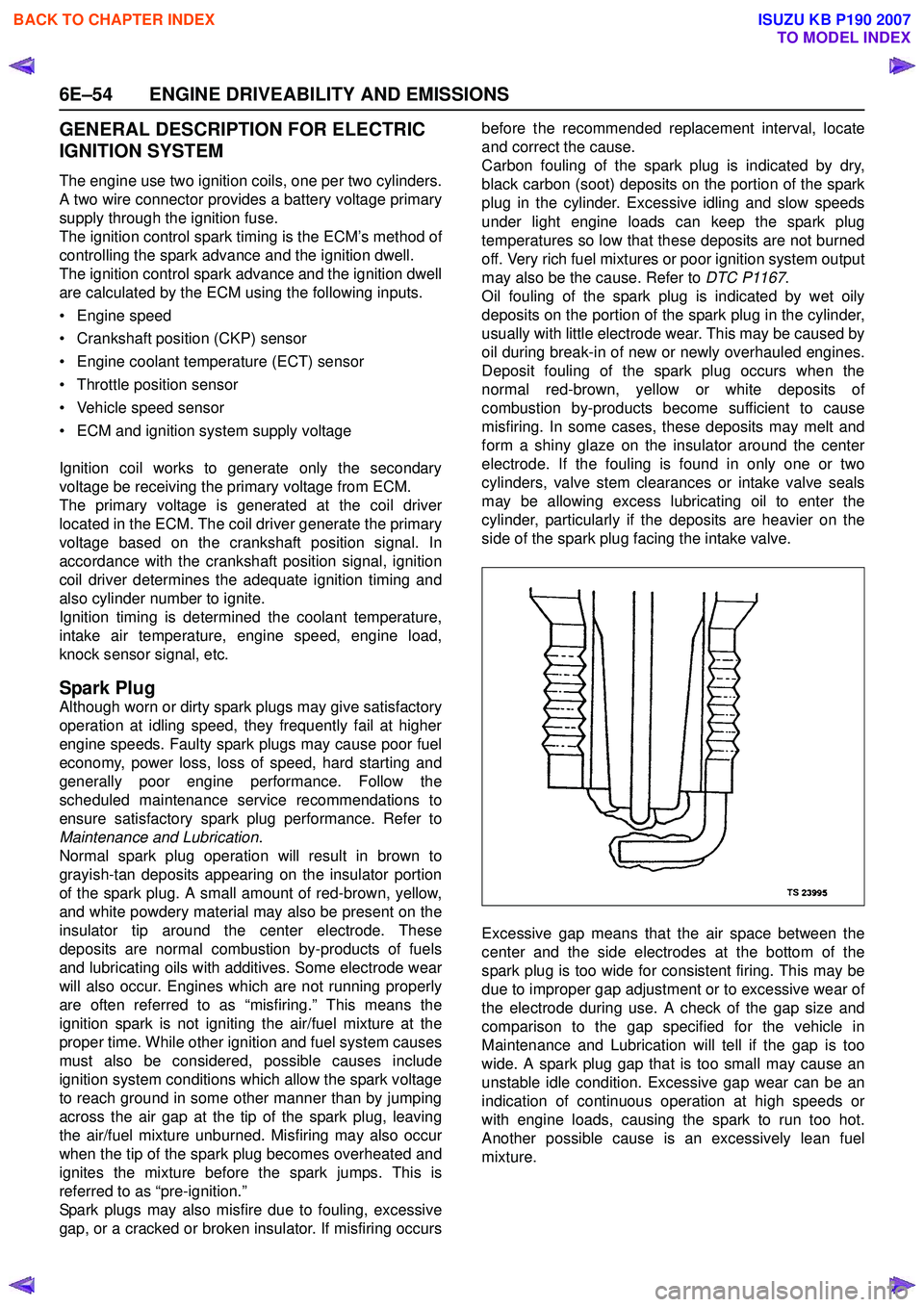
Excessive gap means that the air space between the
center and the side electrodes at the bottom of the
spark plug is too wide for consistent firing. This may be
due to improper gap adjustment or to excessive wear of
the electrode during use. A check of the gap size and
comparison to the gap specified for the vehicle in
Maintenance and Lubrication will tell if the gap is too
wide. A spark plug gap that is too small may cause an
unstable idle condition. Excessive gap wear can be an
indication of continuous operation at high speeds or
with engine loads, causing the spark to run too hot.
Another possible cause is an excessively lean fuel
mixture.
BACK TO CHAPTER INDEX
TO MODEL INDEX
ISUZU KB P190 2007
Page 2226 of 6020
6E–56 ENGINE DRIVEABILITY AND EMISSIONS
returned to service. However, if there is any doubt about
the serviceability of a spark plug, replace it. Spark plugs
with cracked or broken insulators should always be
replaced.
BACK TO CHAPTER INDEX
TO MODEL INDEX
ISUZU KB P190 2007