alternator ISUZU KB P190 2007 Workshop Owner's Guide
[x] Cancel search | Manufacturer: ISUZU, Model Year: 2007, Model line: KB P190, Model: ISUZU KB P190 2007Pages: 6020, PDF Size: 70.23 MB
Page 3742 of 6020

Powertrain Interface Module – V6 Page 6E1–81
13.3 Powertrain Interface Module Data List
Diagnostic Data Display
Tech 2 Display Units Displayed Switch On Switch Off
AC Switch On/Off On Off
Cruise Cancel Switch Active/Inactive Active Inactive
Cruise Resume Switch Active/Inactive Active Inactive
Cruise Set Switch Active/Inactive Active Inactive
Cruise Main Switch Active/Inactive Active Inactive
Cruise Control Set Lamp On/Off On Off
Cruise Control On Lamp On/Off On Off
Power Drive Switch On/Off On Off
Power Drive Lamp On/Off On Off
3rd Start Switch On/Off On Off
3rd Start Lamp On/Off On Off
4W D Low Gear Active/Inactive Active Inactive
G-Sensor V 2.43 2.43
G-Sensor Pa 0.027 0.027
Engine Speed RPM 152 1093
Coolant temperature Input °C 35 25
Coolant Temperature % 70 70
Fuel Level Input % 26 26
Fuel Level % 43 43
Alternator Lamp On/Off On Off
Oil Pressure Lamp On/Off On Off
SVS Lamp (Service Vehicle soon) On/Off On Off
Check transmission MIL On/Off On Off
Transmission Oil Temperature Lamp On/Off On Off
LED [ - P - ] On/Off On Off
LED [ - R - ] On/Off On Off
LED [ - N - ] On/Off On Off
LED [ - D - ] On/Off On Off
LED [ - 3 - ] On/Off On Off
LED [ - 2 - ] On/Off On Off
LED [ - 1 - ] On/Off On Off
BACK TO CHAPTER INDEX
TO MODEL INDEX
ISUZU KB P190 2007
Page 3743 of 6020

Powertrain Interface Module – V6 Page 6E1–82
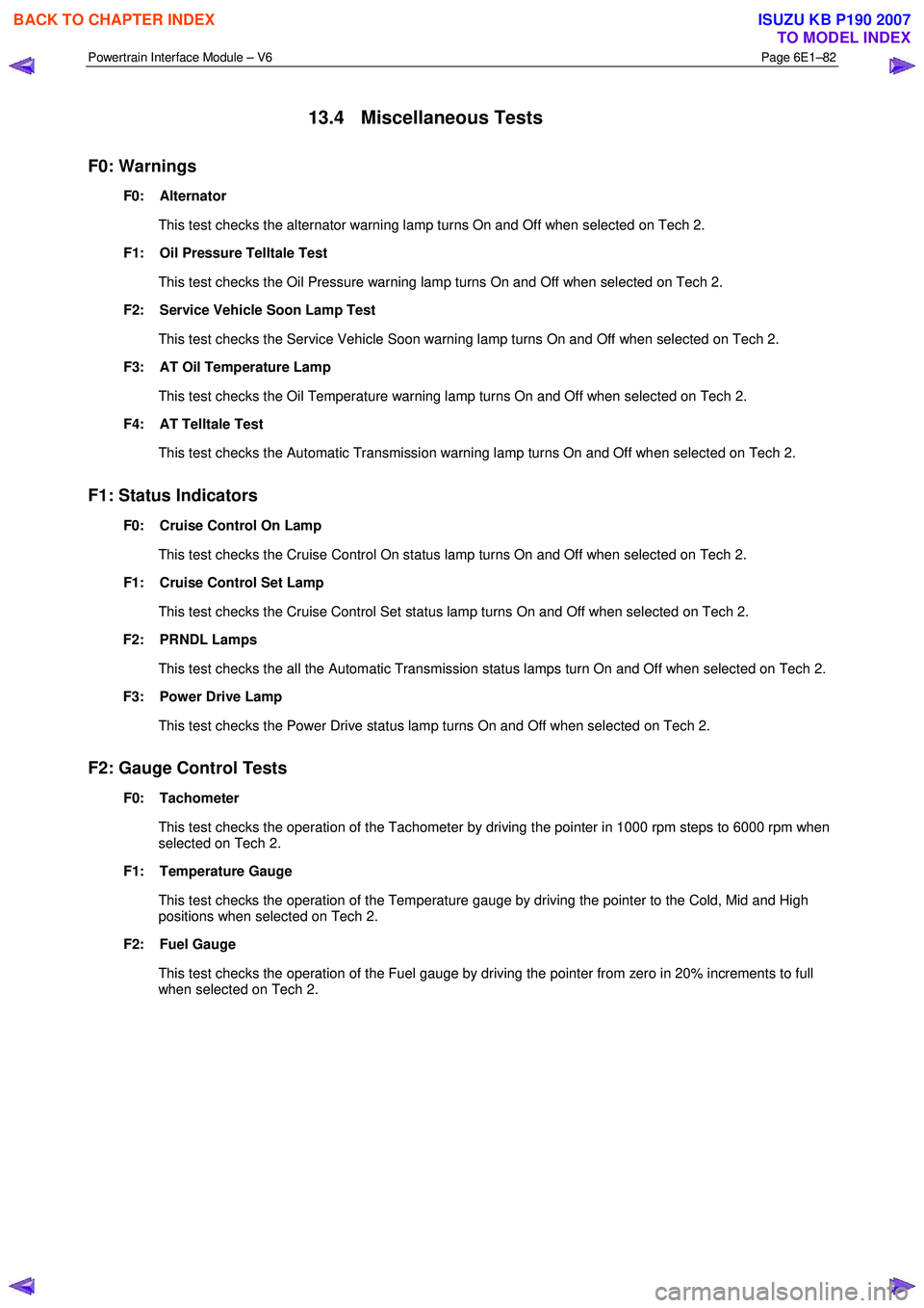
13.4 Miscellaneous Tests
F0: Warnings
F0: Alternator
This test checks the alternator warning lamp turns On and Off when selected on Tech 2.
F1: Oil Pressure Telltale Test
This test checks the Oil Pressure warning lamp turns On and Off when selected on Tech 2.
F2: Service Vehicle Soon Lamp Test
This test checks the Service Vehicle Soon warning lamp turns On and Off when selected on Tech 2.
F3: AT Oil Temperature Lamp
This test checks the Oil Temperature warning lamp turns On and Off when selected on Tech 2.
F4: AT Telltale Test
This test checks the Automatic Transmission warning lamp turns On and Off when selected on Tech 2.
F1: Status Indicators
F0: Cruise Control On Lamp
This test checks the Cruise Control On status lamp turns On and Off when selected on Tech 2.
F1: Cruise Control Set Lamp
This test checks the Cruise Control Set status lamp turns On and Off when selected on Tech 2.
F2: PRNDL Lamps
This test checks the all the Automatic Transmission status lamps turn On and Off when selected on Tech 2.
F3: Power Drive Lamp
This test checks the Power Drive status lamp turns On and Off when selected on Tech 2.
F2: Gauge Control Tests
F0: Tachometer
This test checks the operation of the Tachometer by driving the pointer in 1000 rpm steps to 6000 rpm when
selected on Tech 2.
F1: Temperature Gauge
This test checks the operation of the Temperature gauge by driving the pointer to the Cold, Mid and High
positions when selected on Tech 2.
F2: Fuel Gauge
This test checks the operation of the Fuel gauge by driving the pointer from zero in 20% increments to full when selected on Tech 2.
BACK TO CHAPTER INDEX
TO MODEL INDEX
ISUZU KB P190 2007
Page 3822 of 6020

Automatic Transmission – 4L60E – Electrical Diagnosis Page 7C2–36
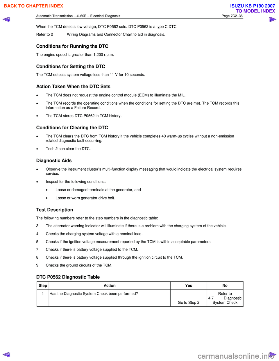
When the TCM detects low voltage, DTC P0562 sets. DTC P0562 is a type C DTC.
Refer to 2 W iring Diagrams and Connector Chart to aid in diagnosis.
Conditions for Running the DTC
The engine speed is greater than 1,200 r.p.m.
Conditions for Setting the DTC
The TCM detects system voltage less than 11 V for 10 seconds.
Action Taken When the DTC Sets
• The TCM does not request the engine control module (ECM) to illuminate the MIL.
• The TCM records the operating conditions when the conditions for setting the DTC are met. The TCM records this
information as a Failure Record.
• The TCM stores DTC P0562 in TCM history.
Conditions for Clearing the DTC
• The TCM clears the DTC from TCM history if the vehicle completes 40 warm-up cycles without a non-emission
related diagnostic fault occurring.
• Tech 2 can clear the DTC.
Diagnostic Aids
• Observe the instrument cluster’s multi-function display messaging that would indicate the electrical system requires
service.
• Inspect for the following conditions:
• Loose or damaged terminals at the generator, and
• Loose or worn generator drive belt.
Test Description
The following numbers refer to the step numbers in the diagnostic table:
3 The alternator warning indicator will illuminate if there is a problem with the charging system of the vehicle.
4 Checks the charging system voltage with a nominal load.
5 Checks if the ignition voltage measurement reported by the TCM is within acceptable parameters.
7 Checks if there is battery voltage supplied to the TCM.
8 Checks if there is battery voltage supplied through the ignition circuit to the TCM.
9 Checks the ground circuits of the TCM.
DTC P0562 Diagnostic Table
Step Action Yes No
1 Has the Diagnostic System Check been performed?
Go to Step 2 Refer to
4.7 Diagnostic
System Check
BACK TO CHAPTER INDEX
TO MODEL INDEX
ISUZU KB P190 2007
Page 3823 of 6020

Automatic Transmission – 4L60E – Electrical Diagnosis Page 7C2–37
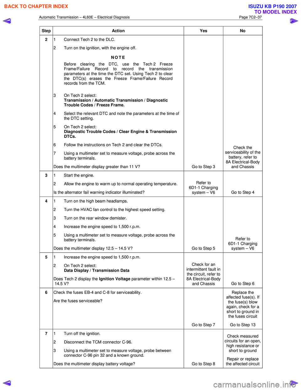
Step Action Yes No
2 1 Connect Tech 2 to the DLC.
2 Turn on the ignition, with the engine off.
NOTE
Before clearing the DTC, use the Tech 2 Freeze
Frame/Failure Record to record the transmission
parameters at the time the DTC set. Using Tech 2 to clear
the DTC(s) erases the Freeze Frame/Failure Record
records from the TCM.
3 On Tech 2 select: Transmission / Automatic Transmission / Diagnostic
Trouble Codes / Freeze Frame.
4 Select the relevant DTC and note the parameters at the time of the DTC setting.
5 On Tech 2 select:
Diagnostic Trouble Codes / Clear Engine & Transmission
DTCs.
6 Follow the instructions on Tech 2 and clear the DTCs.
7 Using a multimeter set to measure voltage, probe across the battery terminals.
Does the multimeter display greater than 11 V? Go to Step 3 Check the
serviceability of the battery, refer to
8A Electrical-Body and Chassis
3 1 Start the engine.
2 Allow the engine to warm up to normal operating temperature.
Is the alternator fail warning indicator illuminated? Refer to
6D1-1 Charging system – V6 Go to Step 4
4 1 Turn on the high beam headlamps.
2 Turn the HVAC fan control to the highest speed setting.
3 Turn on the rear window demister.
4 Increase the engine speed to 1,500 r.p.m.
5 Using a multimeter set to measure voltage, probe across the battery terminals.
Does the multimeter display 12.5 – 14.5 V? Go to Step 5 Refer to
6D1-1 Charging system – V6
5 1 Increase the engine speed to 1,500 r.p.m.
2 On Tech 2 select: Data Display / Transmission Data
Does Tech 2 display the Ignition Voltage parameter within 12.5 –
14.5 V? Check for an
intermittent fault in the circuit, refer to
8A Electrical-Body
and Chassis Go to Step 6
6
Check the fuses EB-4 and C-8 for serviceability.
Are the fuses serviceable?
Go to Step 7 Replace the
affected fuse(s). If the fuse(s) blow
again, check for a short to ground in the fuses circuit
Go to Step 13
7 1 Turn off the ignition.
2 Disconnect the TCM connector C-96.
3 Using a multimeter set to measure voltage, probe between connector C-96 pin 32 and a known ground.
Does the multimeter display battery voltage? Go to Step 8 Check measured
circuits for an open,
high resistance or short to ground
Repair or replace
the affected circuit
BACK TO CHAPTER INDEX
TO MODEL INDEX
ISUZU KB P190 2007
Page 3825 of 6020

Automatic Transmission – 4L60E – Electrical Diagnosis Page 7C2–39
Conditions for Setting the DTC
The TCM detects system voltage greater than 18 V for 10 seconds.
Action Taken When the DTC Sets
•
The TCM does not request the engine control module (ECM) to illuminate the MIL.
• The TCM records the operating conditions when the conditions for setting the DTC are met. The TCM records this
information as a Failure Record.
• The TCM stores DTC P0563 in TCM history.
Conditions for Clearing the DTC
•
The TCM clears the DTC from TCM history if the vehicle completes 40 warm-up cycles without a non-emission
related diagnostic fault occurring.
• Tech 2 can clear the DTC.
Diagnostic Aids
• Observe the instrument cluster’s multi-function display for messaging that would indicate the electrical system
requires service.
• Use Tech 2 to inspect all other modules for voltage related DTCs.
• Running the engine with a battery charger attached may cause DTC P0563 to set.
• Inspect the charging circuit for high resistance.
• Inspect the vehicle battery for open or sulphated cells.
Test Description
The following numbers refer to the step numbers in the diagnostic table:
3 The alternator warning indicator will illuminate if there is a problem with the charging system of the vehicle.
4 Checks the charging system voltage with a minimal load.
5 Checks if there is a difference between the Tech 2 reading and the voltage measure in an earlier step.
DTC P0563 Diagnostic Table
Step Action Yes No
1 Has the Diagnostic System Check been performed?
Go to Step 2 Refer to
4.7 Diagnostic System Check
BACK TO CHAPTER INDEX
TO MODEL INDEX
ISUZU KB P190 2007
Page 3826 of 6020

Automatic Transmission – 4L60E – Electrical Diagnosis Page 7C2–40
Step Action Yes No
2 1 Connect Tech 2 to the DLC.
2 Turn on the ignition, with the engine off.
NOTE
Before clearing the DTC, use the Tech 2 Freeze
Frame/Failure Record to record the transmission
parameters at the time the DTC set. Using Tech 2 to clear
the DTC(s) erases the Freeze Frame/Failure Record
records from the TCM.
3 On Tech 2 select: Transmission / Automatic Transmission / Diagnostic
Trouble Codes / Freeze Frame.
4 Select the relevant DTC and note the parameters at the time of the DTC setting.
5 On Tech 2 select:
Diagnostic Trouble Codes / Clear Engine & Transmission
DTCs.
6 Follow the instructions on Tech 2 and clear the DTCs.
7 On Tech 2 select: Diagnostic Trouble Codes / Read DTC Information.
Has DTC P0562 set? Refer to
4.10 DTC
P0562 – System
Voltage Low Go to Step 3
3 1 Start the engine.
2 Allow the engine to warm up to normal operating temperature.
Is the alternator fail warning indicator illuminated? Refer to
6D1-1 Charging system – V6 Go to Step 4
4 1 Turn off all electrical accessories.
2 Increase the engine speed to 2,000 r.p.m.
3 Using the multimeter set to measure voltage, probe across the battery terminals. Record the measurement for reference.
Does the multimeter display 12.5 – 14.5 V? Go to Step 5 Refer to
6D1-1 Charging system – V6
5 1 Leave the engine running.
2 On Tech 2 select: Data Display / Transmission Data
and observe the Ignition Voltage on Tech 2.
3 Increase the engine speed to 2,000 r.p.m.
Is the difference between the voltage displayed on Tech 2 and the
voltage measurement in Step 4 greater than 1.0 V? Go to Step 7 Go to Step 6
6 Did DTC P0563 reset?
Go to Step 7 Check for an
intermittent fault in the circuit, refer to
8A Electrical-Body and Chassis
7 Replace the TCM, refer to 7C4 Automatic Transmission – 4L60E –
On-vehicle Servicing.
Is the action complete? Go to Step 8 —
BACK TO CHAPTER INDEX
TO MODEL INDEX
ISUZU KB P190 2007
Page 4942 of 6020

8A-4 ELECTRICAL-BODY AND CHASSIS
GENERAL INFORMATION
The body and chassis electrical system operates on a twelve volt power supply with negative ground polarity.
The main harness consists of the engine harness, the instrument harness, the body harness, and the chassis
harness.
The harnesses use a split corrugated tube to protect the wires from the elements.
W ire size is determined by current flow, circuit length, and voltage drop.
All wires have color-coded insulation.
W ire color-codes are shown in the circuit diagrams.
This makes it easier to trace circuits and to make the proper connections.
Each circuit consists of the following:
5. Power source – The battery and the alternator
5. W ires – To carry electrical current through the circuit
5. Fuses – To protect the circuit against current overload
5. Relays – To protect voltage drop between the battery and the circuit parts and to protect the switch points against burning
5. Switches – To open and close the circuit
5. Load – Any device, such as a light or motor, which converts the electrical current into useful work
5. Ground – To allow the current to flow back to the power source
BACK TO CHAPTER INDEX TO MODEL INDEXISUZU KB P190 2007
Page 4958 of 6020

8A-20 ELECTRICAL-BODY AND CHASSIS
Caution:
Never push or tow the vehicle in an attempt to start it.
Extensive damage to the emission system and other
vehicle parts will result.
(Only catalytic converter vehicle)
Treat both the discharged battery and the booster battery
with great care when using jumper cables.
Carefully follow the procedure outlined below.
Always be aware of the dangers of sparking.
Failure to follow the following procedure can result in:
a. Serious personal injury, specially to your eyes.
b. Extensive property damage from a battery explosion, battery acid discharge, or electrical file.
c. Extensive damage to the electronic components o
f
both vehicles.
Do not use a 24 volt booster battery.
Serious damage to the vehicle's electrical system and
electronic components will result.
Jump Starting Procedure
1. Set the parking brake on both vehicles.
2. If one or both vehicles is equipped with a manual transmission, place the gear shift in the "NEUTRAL"
position.
3. Turn off the ignition on both vehicles.
4. Turn off all vehicle lights and accessories.
5 Be sure that the two vehicles are not touching.
Attach the end of one jumper cable to the booster battery
positive terminal.
6
Attach the other end of the same cable to the discharged
battery positive terminal.
7. Once again, check that the booster battery has a 12 volt rating.
8.
Attach one end of the remaining booster cable to the
booster battery negative terminal.
9.
Attach the other end of the booster cable to a solid ground
(such as the air conditioner compressor mounting bracket
or the alternator mounting bracket) in the engine room o
f
the vehicle with the discharged battery.
10.Be sure that the ground connection is at least 500 mm (20 in) from the discharged battery.
BACK TO CHAPTER INDEX TO MODEL INDEXISUZU KB P190 2007