fuse ISUZU KB P190 2007 Workshop Owner's Manual
[x] Cancel search | Manufacturer: ISUZU, Model Year: 2007, Model line: KB P190, Model: ISUZU KB P190 2007Pages: 6020, PDF Size: 70.23 MB
Page 152 of 6020
1-118 HEATER AND AIR CONDITIONING
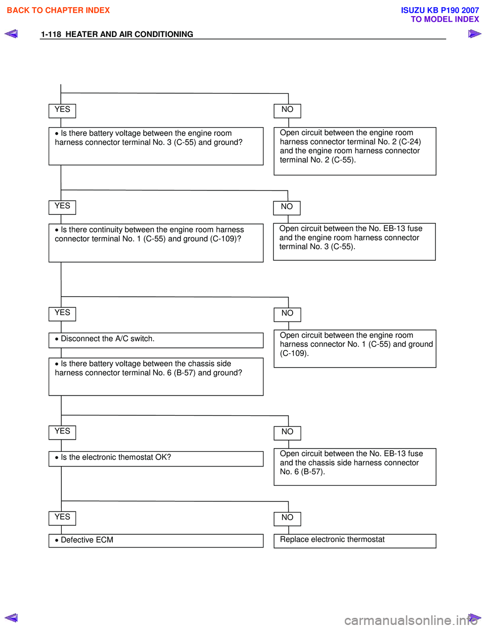
YES
• Disconnect the A/C switch.
• Is there battery voltage between the chassis side
harness connector terminal No. 6 (B-57) and ground?
Open circuit between the engine room
harness connector terminal No. 2 (C-24)
and the engine room harness connector
terminal No. 2 (C-55).
NO YES
• Is there battery voltage between the engine room
harness connector terminal No. 3 (C-55) and ground?
Open circuit between the No. EB-13 fuse
and the engine room harness connector
terminal No. 3 (C-55).
NO YES
• Is there continuity between the engine room harness
connector terminal No. 1 (C-55) and ground (C-109)?
Open circuit between the engine room
harness connector No. 1 (C-55) and ground
(C-109).
NO
YES
• Is the electronic themostat OK? Open circuit between the No. EB-13 fuse
and the chassis side harness connector
No. 6 (B-57).
NO
YES
• Defective ECM Replace electronic thermostat
NO
BACK TO CHAPTER INDEX
TO MODEL INDEX
ISUZU KB P190 2007
Page 608 of 6020

BRAKE CONTROL SYSTEM 5A-15
No. Connector face No. Connector face
H-6
White
Engine room ~ INST P-7
Battery (ALT)
H-7
White
Engine room ~ INST P-10
SilverEngine ground
H-9
White
Engine room ~ Chassis P-11
SilverFuse & relay box
H-15
White
Engine room ~ Chassis
H-18
White
Engine room ~ INST
H-48
White
Engine room ~ INST
P-1
Silver
Battery (+)
P-2
Silver
Relay & Fuse box
P-5
Silver
Battery (-)
P-6
Silver
Body ground
BACK TO CHAPTER INDEX
TO MODEL INDEX
ISUZU KB P190 2007
Page 617 of 6020
5A-24 BRAKE CONTROL SYSTEM
Computer System Service Precautions
The Anti-lock Brake System and Electronic Brake-force
Distribution interfaces directly with the Electronic
Hydraulic Control Unit (EHCU) which is a control
computer that is similar in some regards to the Engine
Control Module. These modules are designed to
withstand normal current draws associated with vehicle
operation. However, care must be taken to avoid
overloading any of the EHCU circuits. In testing for
opens or shorts, do not ground or apply voltage to any
of the circuits unless instructed to do so by the
appropriate diagnostic procedure. These circuits should
only be tested with a high impedance multimeter
5-8840-0366-0 or special tools as described in this
section. Power should never be removed or applied to
any control module with the ignition in the “ON” position.
Before removing or connecting battery cables, fuses or
connectors, always turn the ignition switch to the “OFF”
position.
General Service Precautions
The following are general precautions which should be
observed when servicing and diagnosing the Anti-lock
Brake System and/or other vehicle systems. Failure to
observe these precautions may result in Anti-lock Brake
System and Electronic Brake-force Distribution
damage.
• If welding work is to be performed on the vehicle using an electric arc welder, the EHCU and valve
block connectors should be disconnected before the
welding operation begins.
• The EHCU and valve block connectors should never be connected or disconnected with the
ignition “ON”.
Note:
• If only rear wheels are rotated using jacks or drum tester, the system will diagnose a speed sensor
malfunction and the “ABS and Brake” warning lamp
will illuminate. But actually no trouble exists. W hen
the DTC is not detected and the ABS and BRAKE
warning lamp is on, “How to erase code” is
performed and an ABS and BRAKE warning lamp
are off.
If the battery has been discharged
The engine may stall if the battery has been completely
discharged and the engine is started via jumper cables.
This is because the Anti-lock Brake System (ABS) and
Electronic Brake-force Distribution (EBD) System
requires a large quantity of electricity. In this case, wait
until the battery is recharged, or set the ABS and EBD
to a non-operative state by removing the fuse for the
ABS. After the battery has been recharged, stop the
engine and install the ABS fuse. Start the engine again,
and confirm that the ABS warning Lamp does not light.
Note on Intermittents
As with virtually any electronic system, it is difficult to
identify an intermittent failure. In such a case duplicating
the system malfunction during a test drive or a good
description of vehicle behavior from the customer may
be helpful in locating a “most likely” failed component or
circuit. The symptom diagnosis chart may also be
useful in isolating the failure. Most intermittent
problems are caused by faulty electrical connections or
wiring. W hen an intermittent failure is encountered,
check suspect circuits for:
• Suspected harness damage.
• Poor mating of connector halves or terminals not fully seated in the connector body (backed out).
• Improperly formed or damaged terminals.
Test Driving ABS Complaint Vehicles
If there has been an abnormality in the lighting pattern
of the “ABS” warning lamp, the fault can be located in
accordance with the “DIAGNOSIS BY “ABS” W ARNING
LAMP ILLUMINATION PATTERN”. Although such
problems can be detected by the driver as a vehicle
symptom, it is still necessary to perform a test drive
following the test procedure mentioned below, in order
to reproduce the symptom for problem diagnosis on a
symptom basis:
1. Start the engine and make sure that the “ABS” W /L
goes OFF. If the W /L remains ON, it means that
the Diagnostic Trouble Code (DTC) is stored.
Therefore, read the code and locate the fault.
Note: The DTC cannot be cleared if the vehicle speed
does not exceed about 10km/h (6mph) at DTC, even
though the repair operation is completed.
2. Start the vehicle and accelerate to about 30 km/h (19 mph) or more.
3. Slowly brake and stop the vehicle completely.
4. Then restart the vehicle and accelerate to about 40 km/h (25 mph) or more.
5. Brake at a time so as to actuate the ABS and stop the vehicle.
6. Be cautious of abnormality during the test. If the W /L is actuated while driving, read the DTC and
locate the fault.
7. If the abnormality is not reproduced by the test, make best efforts to reproduce the situation
reported by the customer.
8. If the abnormality has been detected, repair in accordance with the “SYMPTOM DIAGNOSIS”.
Note:
• Be sure to perform a test drive on a wide, even road
with light traffic.
• If an abnormality is detected, be sure to suspend the test and start trouble diagnosis at once.
BACK TO CHAPTER INDEX
TO MODEL INDEX
ISUZU KB P190 2007
Page 637 of 6020

5A-44 BRAKE CONTROL SYSTEM
Brake Pedal Feed Is Abnormal
Step Action Value(s) Yes No
1 Is the stop light actuated when the brake pedal is
depressed? - Go to Step 2 Go to Step 3
2 1. Turn the ignition switch off.
2. Disconnect EHCU connector. Is the check voltage for EHCU connector terminals
when brake pedal is depressed than battery voltage? - Go to Step 4 Harness NG
between stop light SW and EHCU.
Go to Step 6
3 Is stop light fuse normal?
- Go to Step 5 Replace stop
light fuse.
Go to Step 6
4 Is the check continuity between EHCU connector to body grounded?
- Go to Step 6 Repair body
grounded harness.
Go to Step 6
5 Is stop light switch operation normal?
- Repair stop
light harness.
Go to Step 6 Replace stop
light switch.
Go to Step 6
6 Reconnect all components, ensure all components are properly mounted.
Is this step finished? - Repeat the
“Basic
diagnostic
flow chart” Go to Step 6
BACK TO CHAPTER INDEX
TO MODEL INDEX
ISUZU KB P190 2007
Page 639 of 6020
5A-46 BRAKE CONTROL SYSTEM
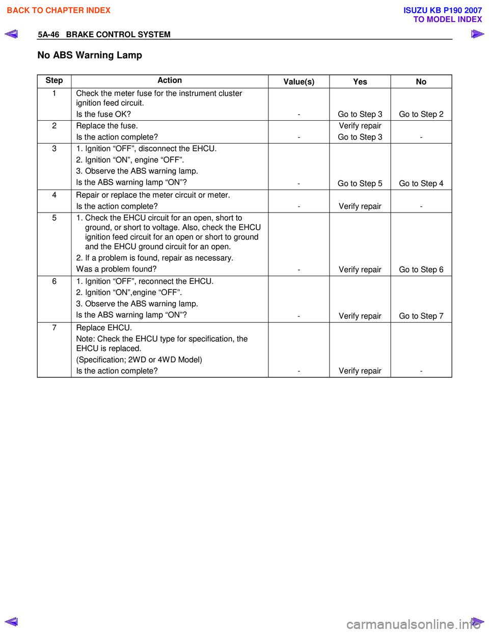
No ABS Warning Lamp
Step Action Value(s) Yes No
1 Check the meter fuse for the instrument cluster
ignition feed circuit.
Is the fuse OK? - Go to Step 3 Go to Step 2
2 Replace the fuse. Is the action complete? - Verify repair
Go to Step 3 -
3 1. Ignition “OFF”, disconnect the EHCU. 2. Ignition “ON”, engine “OFF”.
3. Observe the ABS warning lamp. Is the ABS warning lamp “ON”? - Go to Step 5 Go to Step 4
4 Repair or replace the meter circuit or meter.
Is the action complete? - Verify repair -
5 1. Check the EHCU circuit for an open, short to
ground, or short to voltage. Also, check the EHCU
ignition feed circuit for an open or short to ground
and the EHCU ground circuit for an open.
2. If a problem is found, repair as necessary. W as a problem found? - Verify repair Go to Step 6
6 1. Ignition “OFF”, reconnect the EHCU.
2. Ignition “ON”,engine “OFF”.
3. Observe the ABS warning lamp. Is the ABS warning lamp “ON”? - Verify repair Go to Step 7
7 Replace EHCU.
Note: Check the EHCU type for specification, the
EHCU is replaced.
(Specification; 2W D or 4W D Model)
Is the action complete? - Verify repair -
BACK TO CHAPTER INDEX
TO MODEL INDEX
ISUZU KB P190 2007
Page 788 of 6020
TROUBLESHOOTING 6 – 3
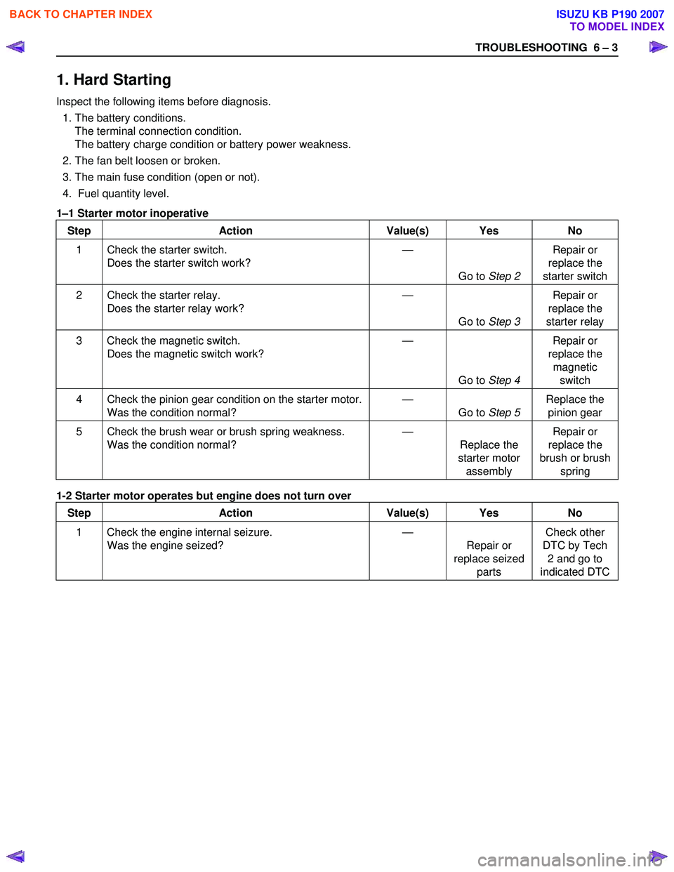
1. Hard Starting
Inspect the following items before diagnosis.
1. The battery conditions. The terminal connection condition.
The battery charge condition or battery power weakness.
2. The fan belt loosen or broken.
3. The main fuse condition (open or not).
4. Fuel quantity level.
1 –1 Starter motor inoperative
Step Action Value(s) Yes No
1 Check the starter switch. Does the starter switch work? —
Go to Step 2 Repair or
replace the
starter switch
2 Check the starter relay. Does the starter relay work? —
Go to Step 3 Repair or
replace the
starter relay
3 Check the magnetic switch. Does the magnetic switch work? —
Go to Step 4 Repair or
replace the magnetic switch
4 Check the pinion gear condition on the starter motor. Was the condition normal? —
Go to Step 5 Replace the
pinion gear
5 Check the brush wear or brush spring weakness. Was the condition normal? —
Replace the
starter motor assembly Repair or
replace the
brush or brush spring
1-2 Starter motor operates but engine does not turn over
Step Action Value(s) Yes No
1 Check the engine internal seizure. Was the engine seized? —
Repair or
replace seized parts Check other
DTC by Tech 2 and go to
indicated DTC
BACK TO CHAPTER INDEX
TO MODEL INDEX
ISUZU KB P190 2007
Page 1034 of 6020
ENGINE ELECTRICAL 6D – 33
PRE-HEATING SYSTEM
INSPECTION AND REPAIR
Make the necessary adjustments, repairs, and part replacement if excessive wear of damage is discovered during
inspection.
VISUAL CHECK
Check the main fuses and glow indicator for damage.
Replace the part(s) if required.
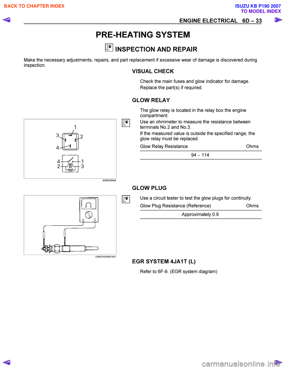
GLOW RELAY
The glow relay is located in the relay box the engine
compartment.
825R300046
Use an ohmmeter to measure the resistance between
terminals No.2 and No.3.
If the measured value is outside the specified range, the
glow relay must be replaced.
Glow Relay Resistance Ohms
94 − 114
GLOW PLUG
LNW21KSH001401
Use a circuit tester to test the glow plugs for continuity.
Glow Plug Resistance (Reference) Ohms
Approximately 0.9
EGR SYSTEM 4JA1T (L)
Refer to 6F-9. (EGR system diagram)
BACK TO CHAPTER INDEX
TO MODEL INDEX
ISUZU KB P190 2007
Page 1052 of 6020

6E-18 Engine Control System (4JH1)
Component Locator
Engine Controls Component Views
3
4
1 2
6
45
Legend
1. Mass Air Flow (MAF) & Intake Air Temperature (IAT) Sensor Assembly
2. Throttle Cable
3. Air Cleaner Case
4. Battery
5. Relay & Fuse Box
6. EGR Cooler (Euro3) / EGR Pipe (Except Euro3)
BACK TO CHAPTER INDEX
TO MODEL INDEX
ISUZU KB P190 2007
Page 1056 of 6020
6E-22 Engine Control System (4JH1)
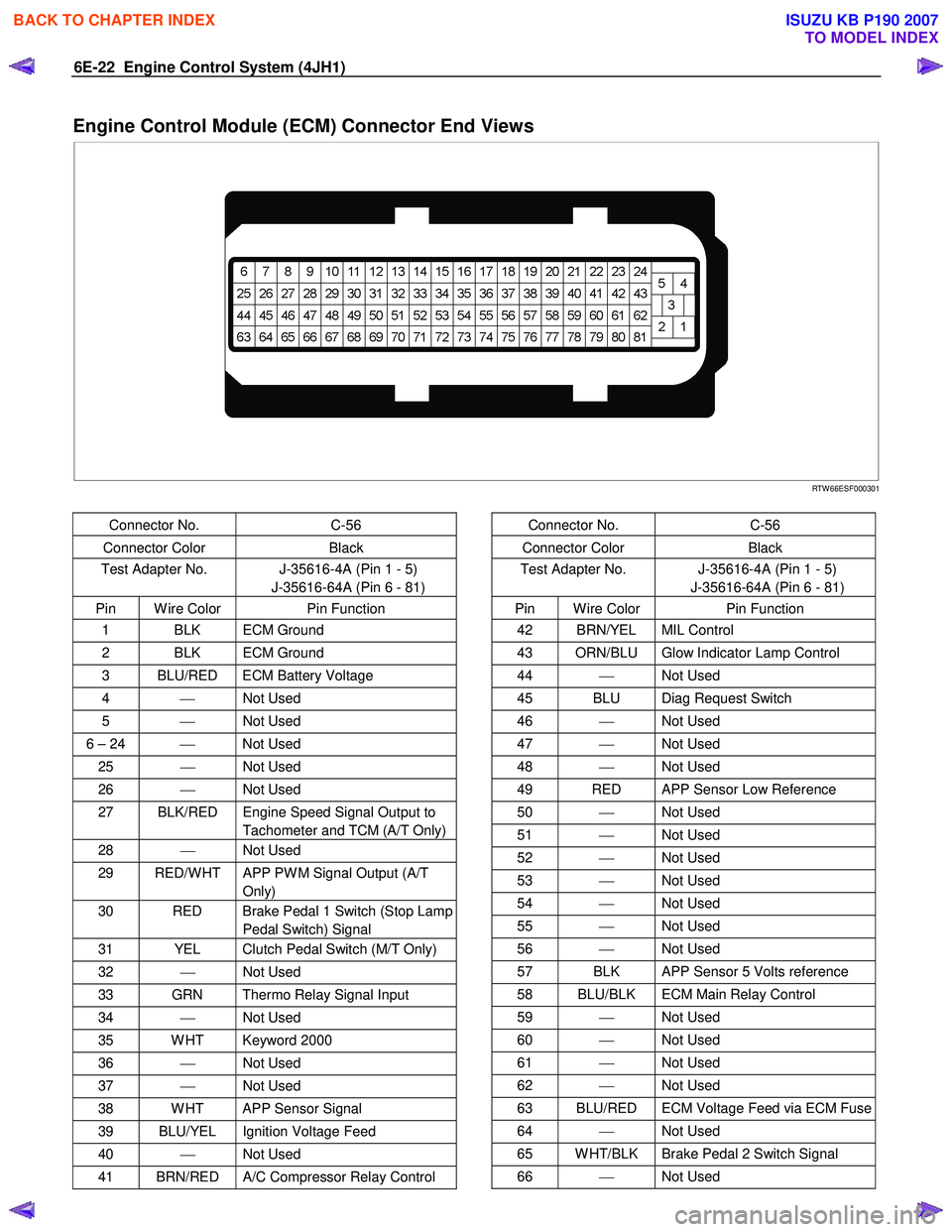
Engine Control Module (ECM) Connector End Views
RTW 66ESF000301
Connector No. C-56
Connector Color Black
Test Adapter No. J-35616-4A (Pin 1 - 5)
J-35616-64A (Pin 6 - 81)
Pin W ire Color Pin Function
1 BLK ECM Ground
2 BLK ECM Ground
3 BLU/RED ECM Battery Voltage
4 Not Used
5 Not Used
6 – 24 Not Used
25 Not Used
26 Not Used
27 BLK/RED Engine Speed Signal Output to
Tachometer and TCM (A/T Only)
28 Not Used
29 RED/W HT APP PW M Signal Output (A/T
Only)
30 RED Brake Pedal 1 Switch (Stop Lamp Pedal Switch) Signal
31 YEL Clutch Pedal Switch (M/T Only)
32 Not Used
33 GRN Thermo Relay Signal Input
34 Not Used
35 W HT Keyword 2000
36 Not Used
37 Not Used
38 W HT APP Sensor Signal
39 BLU/YEL Ignition Voltage Feed
40 Not Used
41 BRN/RED A/C Compressor Relay Control
Connector No. C-56
Connector Color Black
Test Adapter No. J-35616-4A (Pin 1 - 5)
J-35616-64A (Pin 6 - 81)
Pin W ire Color Pin Function
42 BRN/YEL MIL Control
43 ORN/BLU Glow Indicator Lamp Control
44 Not Used
45 BLU Diag Request Switch
46 Not Used
47 Not Used
48 Not Used
49 RED APP Sensor Low Reference
50 Not Used
51 Not Used
52 Not Used
53 Not Used
54 Not Used
55 Not Used
56 Not Used
57 BLK APP Sensor 5 Volts reference
58 BLU/BLK ECM Main Relay Control
59 Not Used
60 Not Used
61 Not Used
62 Not Used
63 BLU/RED ECM Voltage Feed via ECM Fuse
64 Not Used
65 W HT/BLK Brake Pedal 2 Switch Signal
66 Not Used
BACK TO CHAPTER INDEX
TO MODEL INDEX
ISUZU KB P190 2007
Page 1075 of 6020
Engine Control System (4JH1) 6E-41
Scan Tool Does Not Power Up
Circuit Description
The data link connector (DLC) is a standardized 16-
cavity connector. Connector design and location is
dictated by an industry wide standard, and is required to
provide the following:
• Scan tool power battery positive voltage at terminal
16.
• Scan tool power ground at terminal 4.
•
Common signal ground at terminal 5.
The scan tool will power up with the ignition OFF. Some
modules however, will not communicate unless the
ignition is ON.
Scan tool Does Not Power Up
Schematic Reference: Engine Controls Schematics
Connector End View Reference: Engine Controls
Connector End Views
Step Action Value(s) Yes No
1 Important: Make sure the scan tool works properly
on another vehicle before using this chart.
1. Turn OFF the ignition.
2. Inspect the Meter (+B) (10A) fuse (C-19) in the cabin fuse box.
Is the Meter (+B) (10A) fuse (C-19) open?
Go to Step 2 Go to Step 3
2 Replace the Meter (+B) (10A) fuse (C-19). If the fuse continues to open, repair the short to ground on one
of the circuits that is fed by the Meter (+B) (10A) fuse
(C-19) or replace the shorted attached component
fed by the Meter (+B) (10A) fuse (C-19).
Did you complete the repair?
Go to Step 7
3 1. Check each circuit at the data link connector
(DLC) (B-58 connector) for a backed out, spread
or missing terminal.
2. Repair the terminal as necessary.
Did you find and complete the repair?
Go to Step 7 Go to Step 4
4 Connect a test lamp between the B+ circuit (pin 16 of B-58 connector) at the DLC and a known ground.
Does the test lamp illuminate?
Go to Step 6 Go to Step 5
5 Repair the open in the battery voltage circuit to the DLC.
Did you complete the repair?
Go to Step 7
6 1. Test each ground circuit at the DLC (pins 4 and 5
of B-58 connector) for an open circuit or high
resistance.
2. Repair the circuit(s) as necessary.
Did you find and correct the condition?
Go to Step 7 Go to Intermittent
Conditions
7 1. Connect the scan tool to the DLC. 2. Attempt to turn ON the scan tool.
Does the scan tool ON?
System OK Go to Step 1
BACK TO CHAPTER INDEX
TO MODEL INDEX
ISUZU KB P190 2007