oil capacity ISUZU KB P190 2007 Workshop Owner's Manual
[x] Cancel search | Manufacturer: ISUZU, Model Year: 2007, Model line: KB P190, Model: ISUZU KB P190 2007Pages: 6020, PDF Size: 70.23 MB
Page 2844 of 6020

Engine Mechanical – V6 Page 6A1–67
Page 6A1–67
Replace
NOTE
• Quicker and more complete draining will
occur if the engine oil is at normal operating
temperature. However, care must be taken to
avoid scalding from the hot oil.
• It recommended the oil filter be changed at
each engine oil change, refer to 3.2 Oil Filter.
1 Remove the oil fill cap.
2 To ensure complete draining of the oil pan, raise the front and rear of the vehicle to maintain a level attitude. If not
using a hoist, support the vehicle with safety stands, refer to Section 0A General Information.
3 Clean any foreign material from around the oil drain pl ug and place a suitable, clean drain tray under the engine.
The oil may be hot. Avoid contact with the oil.
Ensure that eyes and skin are protected.
4 Remove the drain plug (1), taking care to avoid sca lding from the hot oil. Allow the oil to drain.
5 Clean and inspect the drain plug threads . If damaged, replace the drain plug.
Figure 6A1 – 24
6 Once the oil has completely drained, reinstall the dr ain plug and tighten to the correct torque specification.
Oil pan drain plug
torque specificat ion ............................................ 25.0 Nm
7 Replace the oil filter, refer to 3.2 Oil Filter.
8 Lower the vehicle to the ground and fill with the specified amount of SAE 5W30 lubricant.
Engine Oil Capacity:
With Oil Filter Change........................................6.5 litres
9 Install the oil fill cap.
10 Start the engine and check for leaks.
BACK TO CHAPTER INDEX
TO MODEL INDEX
ISUZU KB P190 2007
Page 3127 of 6020

Engine Mechanical – V6 Page 6A1–350
Page 6A1–350
Lubrication System
Oil Type.................................................................................................................. SAE 5 W30
Oil Capacity – with Filter................................................................................................... 6. 5 L
Oil Pressure – Mini mum at idle ......................................................................................69 kPa
Oil Pressure – Minimum at 2000 r.p.m. ....................................................................... 138 kPa
Piston Cooling Jet Valve Op ening Pressure...................................................... 170 – 230 kPa
BACK TO CHAPTER INDEX
TO MODEL INDEX
ISUZU KB P190 2007
Page 3399 of 6020

Engine Management – V6 – Diagnostics Page 6C1-2–121
Step Action Yes No
10 Replace the ECM. Refer to 6C1-3 Engine Management – V6 –
Service Operations.
W as the repair completed? Go to Step 11 —
11 1 Using Tech 2, clear the DTCs.
2 Switch off the ignition for 30 seconds.
3 Start the engine.
4 Operate the vehicle within the conditions for running the DTC.
Does any of the ignition coil control circuit DTCs fail this ignition
cycle? Go to Step 2 Go to Step 12
12 Using Tech 2, select the DTC display function.
Does Tech 2 display any DTCs? Go to the
appropriate DTC
Table in this Section System OK
When all diagnosis and repairs are completed, check the system for correct operation.
7.23 DTC P0420 or P0430
DTC Descriptors
This diagnostic procedure supports the following DTCs:
• DTC P0420 Catalyst System Low Efficiency Bank 1
• DTC P0430 Catalyst System Low Efficiency Bank 2
Circuit Description
To maintain a reasonably low emission level of hydrocarbons (HC), carbon monoxide (CO), and oxides of nitrogen
(NOx) a 3-way catalytic converter (TW C) is used. The catalyst within the converter promotes a chemical reaction that
oxidizes the HC and CO present in the exhaust gas. This reaction converts the gases into harmless water vapour and
carbon dioxide. The catalyst also reduces the NOx, converting the NOx into nitrogen. The engine control module (ECM)
monitors this process using the post catalyst heated oxygen sensor (HO2S) signal. The post-catalyst HO2S located in
the exhaust stream after the TW C, produces an output signal that indicates the oxygen storage capacity of the catalyst.
The oxygen storage capacity (OSC) determines the ability of the catalyst to convert the exhaust emissions effectively. If
the catalyst is functioning correctly, the post-catalyst HO2S signal will be far less active than the signal produced by the
pre-catalyst HO2S.
To determine OSC, the ECM commands a rich air / fuel mixture until all oxygen is removed from the catalyst. The ECM
then commands a lean air / fuel mixture and monitors the rear heated oxygen sensors to calculate the oxygen storage
capacity. The catalyst is operated in this mode until one of the following conditions occur:
• The oxygen stored in the catalyst exceeds a calibrated threshold, which is determined from the rear HO2S signal.
• The rear HO2S indicates the catalyst to be completely saturated with oxygen, which is determined from the rear
HO2S signal.
If the ECM detects the average OSC is less than a threshold, this DTC sets. This indicates that the TW C oxygen
storage capacity is below a threshold considered acceptable.
Conditions for Running the DTC
• Before the ECM can report, the following DTCs must run and pass:
DTC P0420 or P0430 failed, DTCs P0030, P0031, P0032, P0036, P0037, P0038, P0050, P0051, P0052, P0053,
P0056, P0057, P0058, P0059, P0101, P0102, P0103, P0121, P0122, P0123, P0130, P0131, P0132, P0133,
P0135, P0137, P0138, P0139, P0140, P0141, P0150, P0151, P0152, P0153, P0155, P0157, P0158, P0159,
P0160, P0161, P0221, P0222, P0223, P0335, P0336, P0338, P167A, P167B, P2096, P2097, P2098, P2099,
P2195, P2196, P2197, P2198, P2232, P2235, P2237, P2240, P2243, P2247, P2251, P2254, P2270, P2271,
P2272, P2273, P2297, P2298, P2626, and P2629.
• The following DTCs are not set:
DTCs P0030, P0031, P0032, P0036, P0037, P0038, P0050, P0051, P0052, P0053, P0056, P0057, P0058,
P0059, P0101, P0102, P0103, P0116, P0117, P0118, P0119, P0121, P0122, P0123, P0125, P0130, P0131,
P0132, P0133, P0135, P0137, P0138, P0139, P0140, P0141, P0150, P0151, P0152, P0153, P0155, P0157,
BACK TO CHAPTER INDEX
TO MODEL INDEX
ISUZU KB P190 2007
Page 3777 of 6020

Automatic Transmission – 4L60E – General Information Page 7C1–17
7 Transmission Specifications
7.1 General
Type
Hydra-matic 4L60E
Special Features
Electronically controlled shift pattern, feel and torque
Converter clutch operation
Overdrive 4th speed range
Selector Location ..................................................................................Floor mounted console
Gear Ratios Park (P) ....................................................................................................................... ........... –
Reverse (R) .................................................................................................................... ... 2.29
Neutral (N) .............................................................................................................................. –
Drive (D – 4) .................................................................................................................. ...... 0.7
Drive (D – 3) .................................................................................................................. ...... 1.0
Second (2) ......................................................................................................................... 1.63
First (1) ...................................................................................................................... ........ 3.06
Shift Speeds Refer to 7C3 Automatic Transmission – 4L60E – Hydraulic and Mechanical Diagnosis
Oil Pressure
Refer to 7C3 Automatic Transmission – 4L60E – Hydraulic and Mechanical Diagnosis
Torque Converter
Number of Elements .................................................................. 3 plus torque converter clutch
Torque Converter Diameter and End Play
HFV6 ........................................................................................................................... 258 mm
End Play .............................................................................................................. 0.1 – 0.5 mm
Lubricant
Type recommended ................................................................................................ Dexron
® III
Capacity......................... Nominal only. Check when transmission is at operating temperature
Service Refill ............................................................................................................... 4. 8 litres
Total (Dry)................................................................................................................... 8 .8 litres
Fluid Cooling.....................................Transmission fluid to engine coolant in one radiator tank
Clutches and Band 2 – 4 Band:
Type........................................................................................... Composition lined, steel band
Operation: ..................................................................................................................... .. Servo
Adjustment: ................................................................................................ Selective Apply Pin
Pin Size and Identification.
65.82 – 66.12 mm ...................................................................................................... 1 Groove
67.23 – 67.53 mm ...................................................................................................... 2 Groove
68.64 – 68.94 mm ....................................................................................................No Groove
Reverse Input Clutch Type................................................................................................................Multiple we t disc
Backing plate ........................................................................................................ (1) Select ive
Clutch plate (numbers):
Steel ....................................................................................................................................... 4
Composition............................................................................................................................ 4
Belleville ..................................................................................................................... ............ 1
Backing Plate ........................................................................................................ 1 (Selecti ve)
Backing plate, identification and thickness:
BACK TO CHAPTER INDEX
TO MODEL INDEX
ISUZU KB P190 2007
Page 4566 of 6020

7B-2 MSG MODEL
MAIN DATA AND SPECIFICATIONS
Transmission type Fully synchronized 5-forward gears with a constant
mesh type reverse gear.
Transmission Control Direct control with the gear shift lever on the floor.
Gear ratio MSG5K
1st : 4.122
2nd : 2.493
3rd : 1.504
4th : 1.000
5th : 0.855
Rev : 3.720
Oil capacity lit. (US gal.) 1.55(0.41)
W eight ; approx. kg(lbs) 33.3(73.8)
BACK TO CHAPTER INDEX
TO MODEL INDEX
ISUZU KB P190 2007
Page 4653 of 6020
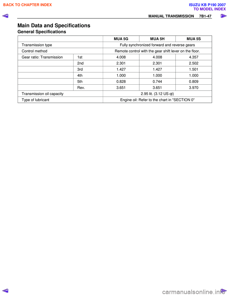
MANUAL TRANSMISSION 7B1-47
Main Data and Specifications
General Specifications
MUA 5G MUA 5H MUA 5S
Transmission type Fully synchronized forward and reverse gears
Control method Remote control with the gear shift lever on the floor.
Gear ratio: Transmission 1st 4.008 4.008 4.357
2nd 2.301 2.301 2.502
3rd 1.427 1.427 1.501
4th 1.000 1.000 1.000
5th 0.828 0.744 0.809
Rev. 3.651 3.651 3.970
Transmission oil capacity 2.95 lit. (3.12 US qt)
Type of lubricant Engine oil: Refer to the chart in "SECTION 0"
BACK TO CHAPTER INDEX
TO MODEL INDEX
ISUZU KB P190 2007
Page 4707 of 6020
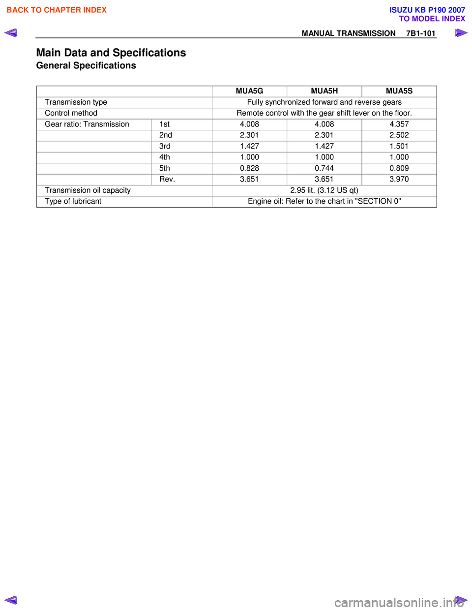
MANUAL TRANSMISSION 7B1-101
Main Data and Specifications
General Specifications
MUA5G MUA5H MUA5S
Transmission type Fully synchronized forward and reverse gears
Control method Remote control with the gear shift lever on the floor.
Gear ratio: Transmission 1st 4.008 4.008 4.357
2nd 2.301 2.301 2.502
3rd 1.427 1.427 1.501
4th 1.000 1.000 1.000
5th 0.828 0.744 0.809
Rev. 3.651 3.651 3.970
Transmission oil capacity 2.95 lit. (3.12 US qt)
Type of lubricant Engine oil: Refer to the chart in "SECTION 0"
BACK TO CHAPTER INDEX
TO MODEL INDEX
ISUZU KB P190 2007
Page 4724 of 6020

Manual Transmission (MUX) 7B1-5
Main Specifications
Walking or Jumping Out of Gear Change lever sliding portion wornand excessive playReplace worn parts
Shift rod and/or quadrant box
sliding faces worn Replace worn parts
Shift arm and synchronizer sleeve
groove worn Replace worn parts
Collar and/or gear thrust faces worn
(Input shaft and counter shaft thrust
play) Replace worn parts
Bearing worn or broken (Input shaft,
counter shaft, and individual gears) Replace bearing(s)
Input shaft spline, output shaft
spline, and synchronizer clutch hub
splines worn Replace input shaft, output shaft,
and synchronizer clutch hub
Synchronizer parts worn or broken Replace worn or broken parts
Taper bolt slack Replace taper bolt
Oil Leakage Oil level too high Drain oil to correct level Improper lubricant Replace lubricant
Drain plug and/or filler plug loose Tighten plug and replenish lubricant
Defective or improperly installed
gasket (s) Replace gasket(s)
Front oil seal worn or scratched Replace oil seal
Rear oil seal worn or scratched Replace oil seal
Model MUX5S
Transmission Type Fully synchronized forward and reverse gears
Control method Remote control with the gear shift lever on the floor
Gear ratio 1st 4.326
2nd 2.557
3rd 1.490
4th 1.000
5th 0.790
Revese 3.942
Transmission oil capacity 3.0 lit. (3.17 US qt)
Type of lubricant BESCO TRANS AXLE OIL (5W-30 SF)
Condition
Possible Cause Correction
BACK TO CHAPTER INDEX
TO MODEL INDEX
ISUZU KB P190 2007
Page 4871 of 6020
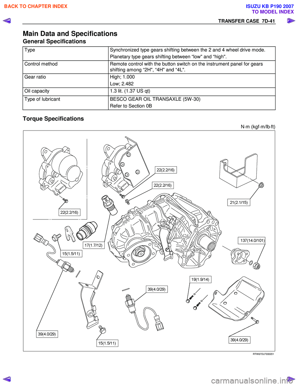
TRANSFER CASE 7D-41
Main Data and Specifications
General Specifications
Type Synchronized type gears shifting between the 2 and 4 wheel drive mode.
Planetary type gears shifting between “low" and “high".
Control method Remote control with the button switch on the instrument panel for gears
shifting among “2H", “4H" and “4L".
Gear ratio High; 1.000
Low; 2.482
Oil capacity 1.3 lit. (1.37 US qt)
Type of lubricant BESCO GEAR OIL TRANSAXLE (5W -30)
Refer to Section 0B
Torque Specifications
N⋅m (kgf ⋅m/lb ⋅ft)
RTW 67DLF000201
BACK TO CHAPTER INDEX
TO MODEL INDEX
ISUZU KB P190 2007
Page 4971 of 6020
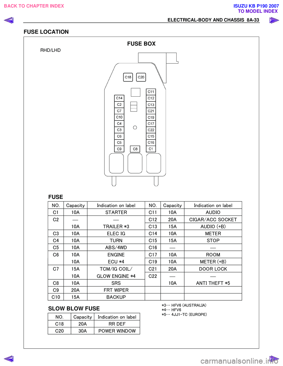
ELECTRICAL-BODY AND CHASSIS 8A-33
FUSE LOCATION
RHD/LHD
FUSE
NO. Capacity Indication on label NO. Capacity Indication on label
C 1 10A STARTER C 1110A AUDIO
C2
C
12 20A CIGAR/ACC SOCKET
10A TRAILER *3 C 13 15A AUDIO (+B)
C3 10A ELEC IG C 14 10A METER
C4 10A TURN C 15 15A STOP
C5 10A ABS/4WD C 16
C6 10A ENGINE C 17 10A ROOM
10A ECU *4 C19 10A METER (+B)
C7 15A TCM/IG COIL/ C2 120A DOOR LOCK
10A GLOW ENGINE *4 C22
C8 10A SRS 10A ANTI THEFT *5
C9 20A FRT WIPER
C10 15A BACKUP
SLOW BLOW FUSE
NO. Capacity Indication on label
C 18 20A RR DEF
C20 30A POWER WINDOW
FUSE BOX
*3 … HFV6 (AUSTRALIA)
*4 … HFV6
*5 … 4JJ 1-TC (EUROPE)
BACK TO CHAPTER INDEX
TO MODEL INDEXISUZU KB P190 2007