sensor ISUZU KB P190 2007 Workshop Repair Manual
[x] Cancel search | Manufacturer: ISUZU, Model Year: 2007, Model line: KB P190, Model: ISUZU KB P190 2007Pages: 6020, PDF Size: 70.23 MB
Page 20 of 6020
0B-2 MAINTENANCE AND LUBRICATION
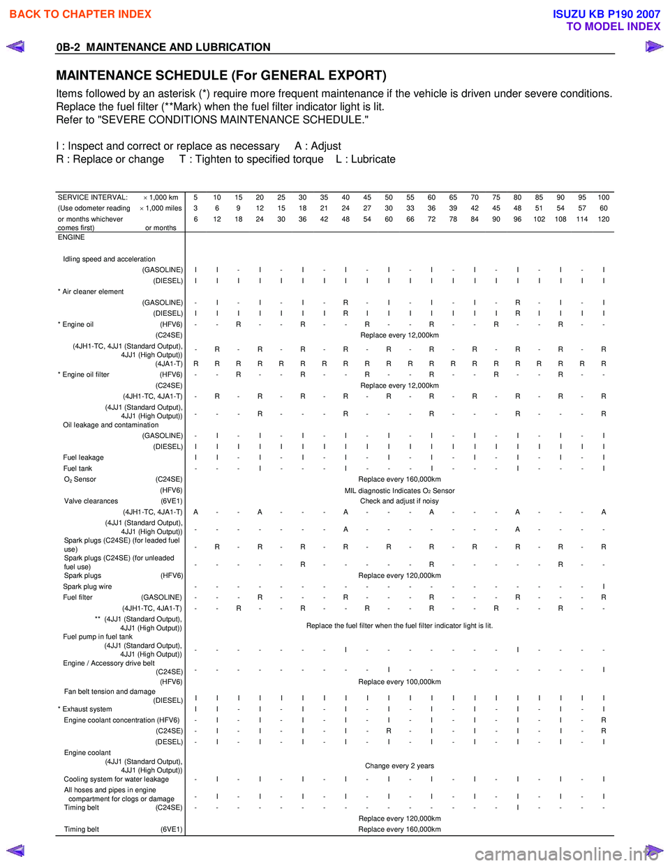
MAINTENANCE SCHEDULE (For GENERAL EXPORT)
Items followed by an asterisk (*) require more frequent maintenance if the vehicle is driven under severe conditions.
Replace the fuel filter (**Mark) when the fuel filter indicator light is lit.
Refer to "SEVERE CONDITIONS MAINTENANCE SCHEDULE."
I : Inspect and correct or replace as necessary A : Adjust
R : Replace or change T : Tighten to specified torque L : Lubricate
SERVICE INTERVAL: × 1,000 km 5 10 15 20 25 30 35 40 45 50 55 60 65 70 75 80 85 90 95 100(Use odometer reading × 1,000 miles 3 6 9 12 15 18 21 24 27 30 33 36 39 42 45 48 51 54 57 60or months whichever
comes first)
or months 6 12 18 24 30 36 42 48 54 60 66 72 78 84 90 96 102 108 114 120
ENGINE
Idling speed and acceleration
(GASOLINE) I I - I - I - I - I - I - I - I - I - I (DIESEL) I I I I I I I I I I I I I I I I I I I I * Air cleaner element
(GASOLINE) - I - I - I - R - I - I - I - R - I - I (DIESEL) I I I I I I I R I I I I I I I R I I I I * Engine oil (HFV6) - - R - - R - - R - - R - - R - - R - - (C24SE) Replace every 12,000km (4JH1-TC, 4JJ1 (Standard Output),
4JJ1 (High Output)) - R - R - R - R - R - R - R - R - R - R
(4JA1-T) R R R R R R R R R R R R R R R R R R R R * Engine oil filter (HFV6) - - R - - R - - R - - R - - R - - R - - (C24SE) Replace every 12,000km (4JH1-TC, 4JA1-T) - R - R - R - R - R - R - R - R - R - R (4JJ1 (Standard Output),
4JJ1 (High Output)) - - - R - - - R - - - R - - - R - - - R
Oil leakage and contamination (GASOLINE) - I - I - I - I - I - I - I - I - I - I (DIESEL) I I I I I I I I I I I I I I I I I I I I Fuel leakage
I I - I - I - I - I - I - I - I - I - I Fuel tank - - - I - - - I - - - I - - - I - - - I O2 Sensor (C24SE) Replace every 160,000km (HFV6)
MIL diagnostic Indicates O2 Sensor Valve clearances (6VE1) Check and adjust if noisy (4JH1-TC, 4JA1-T) A - - A - - - A - - - A - - - A - - - A (4JJ1 (Standard Output),
4JJ1 (High Output)) - - - - - - - A - - - - - - - A - - - -
Spark plugs (C24SE) (for leaded fuel
use) - R - R - R - R - R - R - R - R - R - R
Spark plugs (C24SE) (for unleaded
fuel use) - - - - - R - - - - - R - - - - - R - -
Spark plugs
(HFV6) Replace every 120,000km Spark plug wire - - - - - - - - - - - - - - - - - - - I Fuel filter (GASOLINE) - - - R - - - R - - - R - - - R - - - R (4JH1-TC, 4JA1-T) - - R - - R - - R - - R - - R - - R - - ** (4JJ1 (Standard Output),
4JJ1 (High Output)) Replace the fuel filter when the fuel filter indicator light is lit.
Fuel pump in fuel tank
(4JJ1 (Standard Output),
4JJ1 (High Output)) - - - - - - - I - - - - - - - I - - - -
Engine / Accessory drive belt
(C24SE) - - - - - - - - - I - - - - - - - - - I
(HFV6) Replace every 100,000km Fan belt tension and damage
(DIESEL) I I I I I I I I I I I I I I I I I I I I
* Exhaust system
I I - I - I - I - I - I - I - I - I - I Engine coolant concentration (HFV6) - I - I - I - I - I - I - I - I - I - R (C24SE) - I - I - I - I - R - I - I - I - I - R (DESEL) - I - I - I - I - I - I - I - I - I - I Engine coolant
(4JJ1 (Standard Output),
4JJ1 (High Output)) Change every 2 years
Cooling system for water leakage - I - I - I - I - I - I - I - I - I - I All hoses and pipes in engine
compartment for clogs or damage - I - I - I - I - I - I - I - I - I - I
Timing belt
(C24SE) - - - - - - - - - - - - - - - I - - - - Replace every 120,000km Timing belt (6VE1) Replace every 160,000km
BACK TO CHAPTER INDEX
TO MODEL INDEX
ISUZU KB P190 2007
Page 101 of 6020

HEATER AND AIR CONDITIONING 1-67
RTW 710SH000901
This illustration is based on RHD model
Important Operation -Reassembly
6. Electronic Thermostat
1) Install the electronic thermostat to the evaporator core specified position with the clip.
2) Sensor part must not interfere with the evaporator core.
BACK TO CHAPTER INDEX
TO MODEL INDEX
ISUZU KB P190 2007
Page 125 of 6020
HEATER AND AIR CONDITIONING 1-91
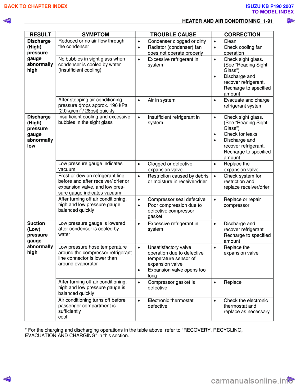
RESULT SYMPTOM TROUBLE CAUSE CORRECTION
Reduced or no air flow through
the condenser
•
Condenser clogged or dirty
• Radiator (condenser) fan
does not operate properly •
Clean
• Check cooling fan
operation
No bubbles in sight glass when
condenser is cooled by water
(Insufficient cooling)
•
Excessive refrigerant in
system
•
Check sight glass.
(See “Reading Sight
Glass”)
• Discharge and
recover refrigerant.
Recharge to specified
amount
Discharge
(High)
pressure
gauge
abnormally
high
After stopping air conditioning,
pressure drops approx. 196 kPa
(2.0kg/cm
2 / 28psi) quickly •
Air in system
•
Evacuate and charge
refrigerant system
Insufficient cooling and excessive
bubbles in the sight glass
•
Insufficient refrigerant in
system
•
Check sight glass.
(See “Reading Sight
Glass”)
• Check for leaks
• Discharge and
recover refrigerant.
Recharge to specified
amount
Low pressure gauge indicates
vacuum •
Clogged or defective
expansion valve •
Replace the
expansion valve
Frost or dew on refrigerant line
before and after receiver/ drier or
expansion valve, and low pres-
sure gauge indicates vacuum •
Restriction caused by debris
or moisture in receiver/drier
•
Check system for
restriction and
replace receiver/drier
Discharge
(High)
pressure
gauge
abnormally
low
After turning off air conditioning,
high and low pressure gauge
balanced quickly
•
Compressor seal defective
• Poor compression due to
defective compressor
gasket •
Replace or repair
compressor
Low pressure gauge is lowered
after condenser is cooled by
water
•
Excessive refrigerant in
system
•
Discharge and
recover refrigerant
Recharge to specified
amount
Low pressure hose temperature
around the compressor refrigerant
line connector is lower than
around evaporator
•
Unsatisfactory valve
operation due to defective
temperature sensor of
expansion valve
• Expansion valve opens too
long •
Replace the
expansion valve
After turning off air conditioning,
high and low pressure gauge is
balanced quickly •
Compressor gasket is
defective
•
Replace
Suction
(Low)
pressure
gauge
abnormally
high
Air conditioning turns off before
passenger compartment is
sufficiently
cool •
Electronic thermostat
defective
•
Check the electronic
thermostat and
replace as necessary
* For the charging and discharging operations in the table above, refer to “RECOVERY, RECYCLING,
EVACUATION AND CHARGING” in this section.
BACK TO CHAPTER INDEX
TO MODEL INDEX
ISUZU KB P190 2007
Page 126 of 6020
1-92 HEATER AND AIR CONDITIONING
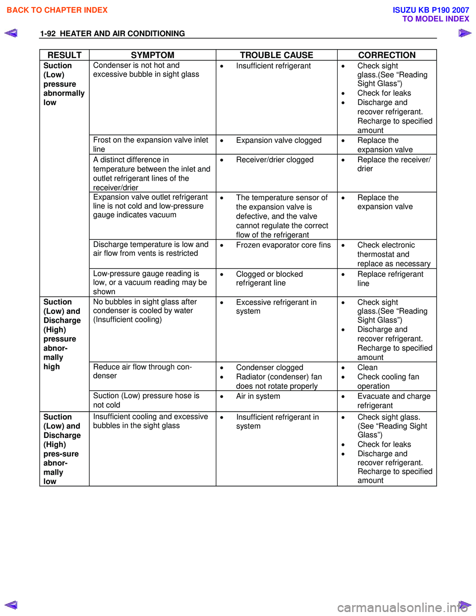
RESULT SYMPTOM TROUBLE CAUSE CORRECTION
Condenser is not hot and
excessive bubble in sight glass
•
Insufficient refrigerant
•
Check sight
glass.(See “Reading
Sight Glass”)
• Check for leaks
• Discharge and
recover refrigerant.
Recharge to specified
amount
Frost on the expansion valve inlet
line •
Expansion valve clogged
•
Replace the
expansion valve
A distinct difference in
temperature between the inlet and
outlet refrigerant lines of the
receiver/drier •
Receiver/drier clogged
•
Replace the receiver/
drier
Expansion valve outlet refrigerant
line is not cold and low-pressure
gauge indicates vacuum
•
The temperature sensor of
the expansion valve is
defective, and the valve
cannot regulate the correct
flow of the refrigerant •
Replace the
expansion valve
Discharge temperature is low and
air flow from vents is restricted
•
Frozen evaporator core fins
•
Check electronic
thermostat and
replace as necessary
Suction
(Low)
pressure
abnormally
low
Low-pressure gauge reading is
low, or a vacuum reading may be
shown •
Clogged or blocked
refrigerant line
•
Replace refrigerant
line
No bubbles in sight glass after
condenser is cooled by water
(Insufficient cooling)
•
Excessive refrigerant in
system
•
Check sight
glass.(See “Reading
Sight Glass”)
• Discharge and
recover refrigerant.
Recharge to specified
amount
Reduce air flow through con-
denser
•
Condenser clogged
• Radiator (condenser) fan
does not rotate properly •
Clean
• Check cooling fan
operation
Suction
(Low) and
Discharge
(High)
pressure
abnor-
mally
high
Suction (Low) pressure hose is
not cold •
Air in system • Evacuate and charge
refrigerant
Suction
(Low) and
Discharge
(High)
pres-sure
abnor-
mally
low Insufficient cooling and excessive
bubbles in the sight glass •
Insufficient refrigerant in
system
•
Check sight glass.
(See “Reading Sight
Glass”)
• Check for leaks
• Discharge and
recover refrigerant.
Recharge to specified
amount
BACK TO CHAPTER INDEX
TO MODEL INDEX
ISUZU KB P190 2007
Page 339 of 6020
FRONT SUSPENSION 3C-19
6. Remove the stabilizer link nuts. Right and left.
7. Remove the wheel speed sensor from the knuckle.
8. Remove back plate.
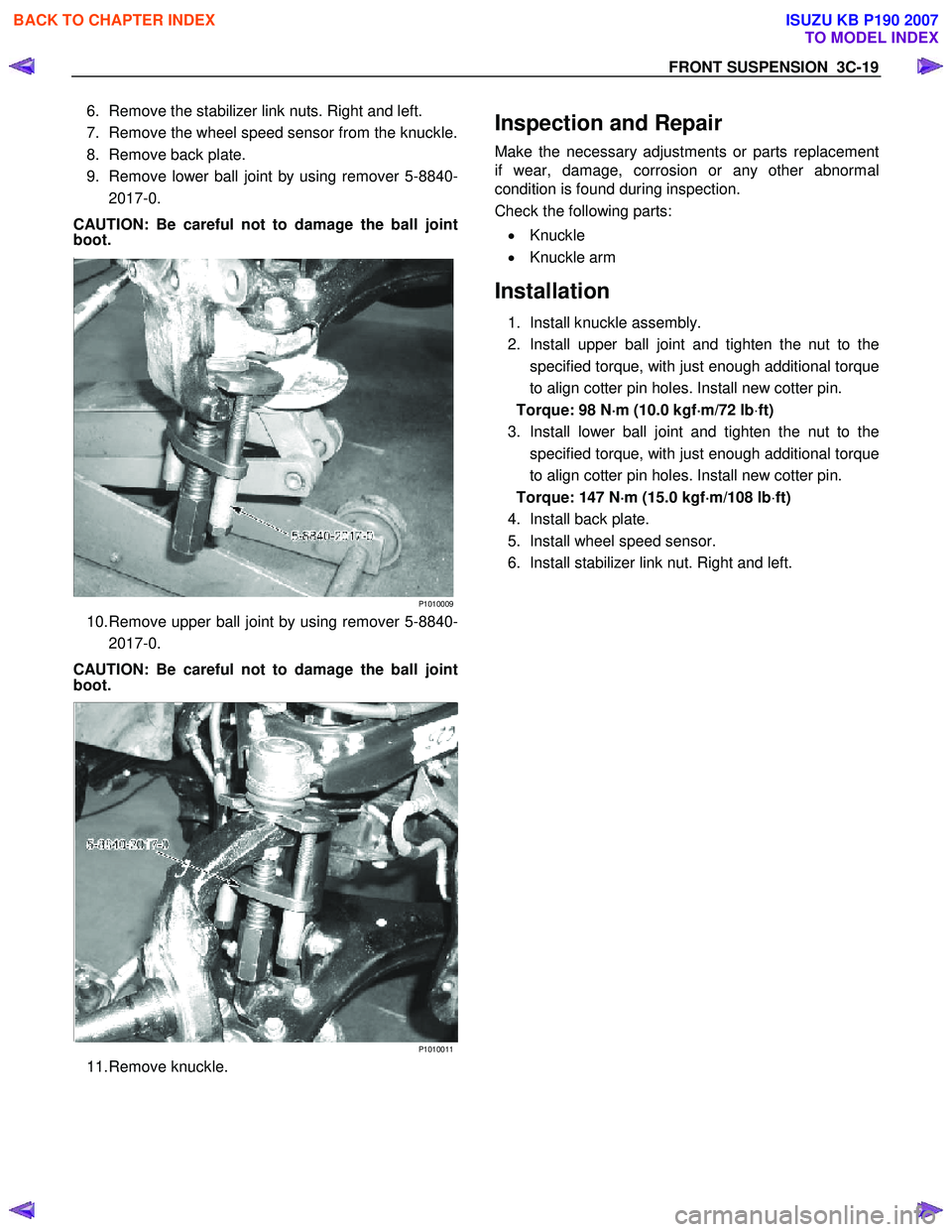
9. Remove lower ball joint by using remover 5-8840- 2017-0.
CAUTION: Be careful not to damage the ball joint
boot.
P1010009
10. Remove upper ball joint by using remover 5-8840-2017-0.
CAUTION: Be careful not to damage the ball joint
boot.
P1010011
11. Remove knuckle.
Inspection and Repair
Make the necessary adjustments or parts replacement
if wear, damage, corrosion or any other abnormal
condition is found during inspection.
Check the following parts:
• Knuckle
• Knuckle arm
Installation
1. Install knuckle assembly.
2. Install upper ball joint and tighten the nut to the specified torque, with just enough additional torque
to align cotter pin holes. Install new cotter pin.
Torque: 98 N ⋅
⋅⋅
⋅
m (10.0 kgf ⋅
⋅⋅
⋅
m/72 lb ⋅ft)
3. Install lower ball joint and tighten the nut to the specified torque, with just enough additional torque
to align cotter pin holes. Install new cotter pin.
Torque: 147 N ⋅
⋅⋅
⋅
m (15.0 kgf ⋅
⋅⋅
⋅
m/108 lb ⋅ft)
4. Install back plate.
5. Install wheel speed sensor.
6. Install stabilizer link nut. Right and left.
BACK TO CHAPTER INDEX
TO MODEL INDEX
ISUZU KB P190 2007
Page 340 of 6020
3C-20 FRONT SUSPENSION
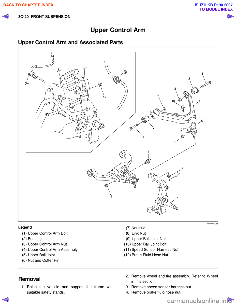
Upper Control Arm
Upper Control Arm and Associated Parts
450R300038
Legend
(1) Upper Control Arm Bolt
(2) Bushing
(3) Upper Control Arm Nut
(4) Upper Control Arm Assembly
(5) Upper Ball Joint
(6) Nut and Cotter Pin
(7) Knuckle
(8) Link Nut
(9) Upper Ball Joint Nut
(10) Upper Ball Joint Bolt
(11) Speed Sensor Harness Nut
(12) Brake Fluid Hose Nut
Removal
1. Raise the vehicle and support the frame with
suitable safety stands.
2. Remove wheel and tire assembly. Refer to W heel
in this section.
3. Remove speed sensor harness nut.
4. Remove brake fluid hose nut.
BACK TO CHAPTER INDEX
TO MODEL INDEX
ISUZU KB P190 2007
Page 341 of 6020
FRONT SUSPENSION 3C-21
5. Remove link nut.
6. Remove upper ball joint by using remover 5-8840- 2017-0.
CAUTION: Be careful not to damage the ball joint
boot.
P1010005
7. Remove upper control arm nut.
8. Remove upper control arm bolt.
9. Remove upper ball joint bolt and nut.
10. Remove upper ball joint.
11. Remove upper control arm assembly.
12. Remove bushing.
Inspection and Repair
Make necessary parts replacement if wear, damage,
corrosion or any other abnormal conditions are found
during inspection.
Check the following parts:
• Upper control arm
• Bushing
Installation
1. Install bushing by using installer 5-8840-0257-0
and 5-8840-2327-0.
P1010062
2. Install upper ball joint and tighten it to the specified
torque.
Torque: 31 N ⋅
⋅⋅
⋅
m (3.2 kgf ⋅
⋅⋅
⋅
m/23 lb ⋅ft)
3. Install nut and cotter pin then tighten the nut to the specified torque, with just enough additional torque
to align cotter pin holes. Install new cotter pin.
Torque: 98 N ⋅
⋅⋅
⋅
m (10.0 kgf ⋅
⋅⋅
⋅
m/72 lb ⋅ft)
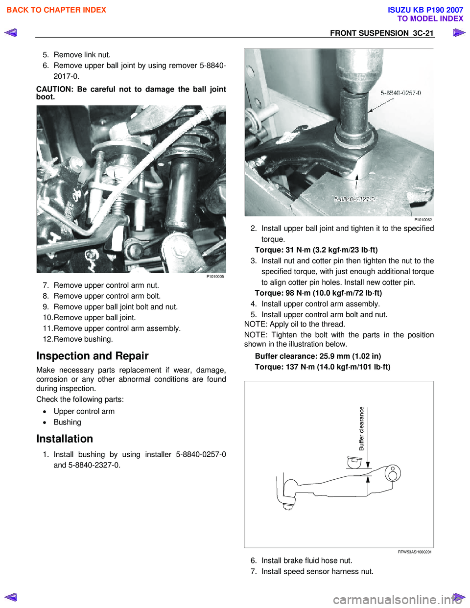
4. Install upper control arm assembly.
5. Install upper control arm bolt and nut.
NOTE: Apply oil to the thread.
NOTE: Tighten the bolt with the parts in the position
shown in the illustration below.
Buffer clearance: 25.9 mm (1.02 in)
Torque: 137 N ⋅
⋅⋅
⋅
m (14.0 kgf ⋅
⋅⋅
⋅
m/101 lb ⋅ft)
RTW 53ASH000201
6. Install brake fluid hose nut.
7. Install speed sensor harness nut.
BACK TO CHAPTER INDEX
TO MODEL INDEX
ISUZU KB P190 2007
Page 358 of 6020

FRONT SUSPENSION 3C-37
Knuckle
Knuckle and Associated Parts
RUW 63CLF000101
Legend
(1) Torsion Bar
(2) Nut and Cotter Pin, Lower Ball Joint
(3) Back Plate
(4) Nut and Cotter Pin, Upper Ball Joint
(5) Nut and Cotter Pin, Tie-rod End
(6) Knuckle Assembly
(7) Knuckle
(8) Needle Bearing (4 ×4 Model Only)
(9) Thrust W asher (4 ×4 Model Only)
(10) Oil Seal (4 ×4 Model Only)
(11) Speed Sensor harness
Removal
1. Raise the vehicle and support the frame with suitable safety stands.
2. Remove wheel and tire assembly. Refer to W heel
in this section.
3. Remove the brake caliper. Refer to Disc Brakes in Brake section.
BACK TO CHAPTER INDEX
TO MODEL INDEX
ISUZU KB P190 2007
Page 359 of 6020

3C-38 FRONT SUSPENSION
4. Remove the hub assembly. Refer to Front Hub
and Disk in this section.
5. Remove tie-rod end from the knuckle. Refer to Power Steering Unit in Steering section.
6. Remove the speed sensor from the knuckle.
7. Loosen torsion bar by height control arm adjust bolt, and then remove torsion bar. Refer to Torsion
Bar in this section.
8. Remove speed sensor harness.
9. Remove back plate.
10. Remove lower ball joint by using remover 5-8840- 2005-0.
CAUTION: Be careful not to damage the ball joint
boot.
901RW 271
11. Remove upper ball joint by using remover 5-8840-
2121-0.
CAUTION: Be careful not to damage the ball joint
boot.
901RW 272
12. Remove knuckle assembly.
13. Remove oil seal. If replacement required. (4×4 Model Only)
14. Remove washer. If replacement required. (4×4 Model Only)
15. Remove needle bearing by using remover 5-8840- 2000-0 and sliding hammer 5-8840-0019-0.
If replacement required. (4 ×4 Model Only)
(4 ×4 Model Only)
RTW 340SH00401
BACK TO CHAPTER INDEX
TO MODEL INDEX
ISUZU KB P190 2007
Page 360 of 6020

FRONT SUSPENSION 3C-39
Inspection and Repair
Make necessary correction or replace parts if wear,
damage, corrosion or any other abnormal condition is
found through inspection.
Check the following parts:
• Knuckle
• Thrust washer (4 ×4 Model Only)
Installation
1. Apply appropriate amount of multipurpose type
grease to the new bearing (Approx. 5 g (0.18 oz))
and install needle bearing by using installer 5-
8840-2128-0 and grip 5-8840-0007-0. (4 ×4 Model
Only)
(4 ×4 Model Only)
901RW 275
2. Apply multipurpose type grease to the thrust
washer, and install washer with chamfered side
facing knuckle. (4 ×4 Model Only)
3. Use a new oil seal, and apply multipurpose type
grease to the area surrounded by the lip (approx. 2
g (0.07 oz)). Then use installer 5-8840-2851-0 (2)
and grip 5-8840-0007-0 (1) to install oil seal. Afte
r
fitting the oil seal to the installer, drive it to the
knuckle using a hammer or bench press until the
tool front face contacts with the thrust washer.
(4 ×4 Model Only)
RTW 73CSH000101
4. Install knuckle assembly.
5. Install upper ball joint and tighten the nut to the specified torque, with just enough additional torque
to align cotter pin holes. Install new cotter pin.
Torque: 98 N ⋅
⋅⋅
⋅
m (10.0 kgf ⋅
⋅⋅
⋅
m/72 lb ⋅
⋅⋅
⋅
ft)
6. Install lower ball joint and tighten the nut to the specified torque, with just enough additional torque
to align cotter pin holes. Install new cotter pin.
Torque: 147 N ⋅
⋅⋅
⋅
m (15.0 kgf ⋅
⋅⋅
⋅
m/108 lb ⋅
⋅⋅
⋅
ft)
7. Install back plate.
8. Install speed sensor harness.
9. Install torsion bar; refer to Torsion Bar in this
section.
NOTE: Adjust the trim height. Refer to Front End
Alignment Inspection and Adjustment in Steering.
BACK TO CHAPTER INDEX
TO MODEL INDEX
ISUZU KB P190 2007