engine mount ISUZU KB P190 2007 Workshop Repair Manual
[x] Cancel search | Manufacturer: ISUZU, Model Year: 2007, Model line: KB P190, Model: ISUZU KB P190 2007Pages: 6020, PDF Size: 70.23 MB
Page 3569 of 6020
Engine Management – V6 – Service Operations Page 6C1-3–45
Ensure the knock sensor is fully seated
before tightening the attaching bolt.
Do not over-tighten the attaching bolt as
incorrect operation of the knock sensor may
result.
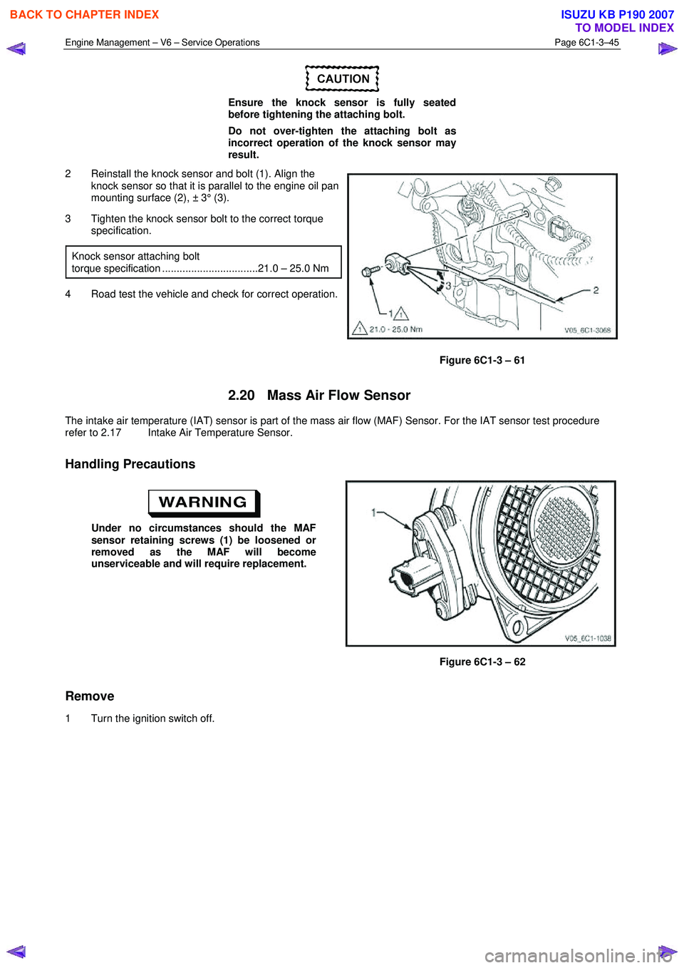
2 Reinstall the knock sensor and bolt (1). Align the knock sensor so that it is parallel to the engine oil pan
mounting surface (2), ± 3° (3).
3 Tighten the knock sensor bolt to the correct torque specification.
Knock sensor attaching bolt
torque specification .................................21.0 – 25.0 Nm
4 Road test the vehicle and check for correct operation.
Figure 6C1-3 – 61
2.20 Mass Air Flow Sensor
The intake air temperature (IAT) sensor is part of the mass air flow (MAF) Sensor. For the IAT sensor test procedure
refer to 2.17 Intake Air Temperature Sensor.
Handling Precautions
Under no circumstances should the MAF
sensor retaining screws (1) be loosened or
removed as the MAF will become
unserviceable and will require replacement.
Figure 6C1-3 – 62
Remove
1 Turn the ignition switch off.
BACK TO CHAPTER INDEX
TO MODEL INDEX
ISUZU KB P190 2007
Page 3571 of 6020
Engine Management – V6 – Service Operations Page 6C1-3–47
2.21 Schrader Valve – Fuel Pressure Gauge
Connection Point
If the Schrader valve is to be removed but not
replaced immediately, it is advisable to
disconnect the battery to avoid possible fuel
discharge if an accidental attempt is made to
start the engine.
Disconnection of the battery affects vehicle
electronic systems. Refer to 6D1-3 Battery –
V6 before disconnecting the battery.
Remove
1 Depressurise the fuel system, refer to 6C Fuel System - V6.
2 Turn the ignition off.
A small amount of fuel may be released when
servicing the fuel pressure test point. To
reduce the chance of personal injury, cover
the fuel pressure test point with a shop towel
to absorb any fuel spillage when the Schrader
valve sealing cap and Schrader valve are
removed. After the procedure, place the towel
in an approved container for disposal.
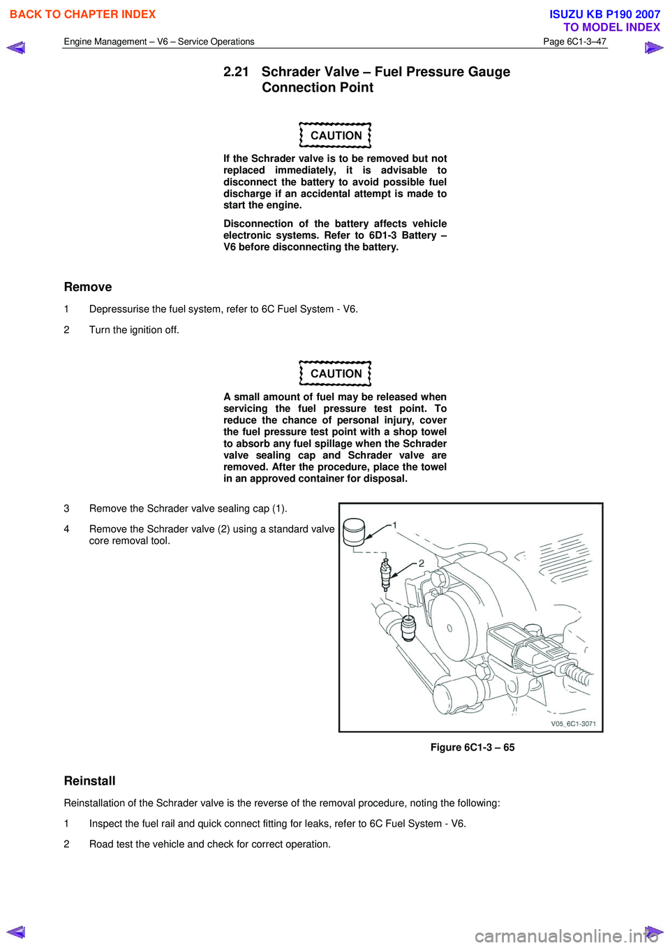
3 Remove the Schrader valve sealing cap (1).
4 Remove the Schrader valve (2) using a standard valve core removal tool.
Figure 6C1-3 – 65
Reinstall
Reinstallation of the Schrader valve is the reverse of the removal procedure, noting the following:
1 Inspect the fuel rail and quick connect fitting for leaks, refer to 6C Fuel System - V6.
2 Road test the vehicle and check for correct operation.
BACK TO CHAPTER INDEX
TO MODEL INDEX
ISUZU KB P190 2007
Page 3590 of 6020
Charging System – V6 Page 6D1-1-3
1 General Information
1.1 Components
Generator
The Mitsubishi generator can be identified visually by its two lower and one upper mounting lugs.
It is mounted to the lower right-hand side of the engine block. It is driven by the same drive belt that drives other engine
ancillaries and requires no periodic drive belt adjustment.
The generator has three phases, incorporating a rotor with six pole pairs fitted and two internal cooling fans; one on the
drive-end and one on the slip-ring end. The rotor is supported by ball bearings in both the drive and slip-ring end
housings. Surrounding the rotor is a stator, which has a three phase delta connected output winding construction on a
ring shaped lamination pack.
The output of the stator winding is rectified by eight diodes that are contained within the slip-ring end housing. Excitation
current is supplied to the rotor field coil via the voltage regulator, the brushes and slip-rings. The electronic voltage
regulator requires no adjustment in service.
The generator has four external connections (refer to Figure 6D1-1 1):
• Generator – Terminal P-9 to the battery positive terminal P-1 via fuse SBF1,
• Generator – E-4 pin 1 to the ECM connection E-60 pin 43 – regulator monitoring,
• Generator – E-4 pin 2 to the ECM connection E60 pin 21 – battery voltage sensing, and
• ground connection via the installation bolts.
Generator Types
The vehicle is fitted with a 120 amp generator.
BACK TO CHAPTER INDEX
TO MODEL INDEX
ISUZU KB P190 2007
Page 3597 of 6020
Charging System – V6 Page 6D1-1-10
3 Minor Service Operations
3.1 Safety Precautions
Observe the following precautions. Failure to observe these precautions will result in serious damage to the generator.
• Only use the generator and voltage regulator in a negative ground system.
• Always refer to 1.2 W ARNING, CAUTION and NOTES before disconnecting the battery.
• W hen installing a battery, fit the positive (+) cable to the battery before fitting the negative cable.
• W hen a slave battery is used for starting purposes, ensure that both batteries are connected in parallel. That is,
positive terminals connected and negative terminals connected.
• Only use jumper leads that have surge protection.
• Disconnect both battery cables when charging the battery. This isolates the generator from the battery and from
the external charging equipment.
• Do not operate the generator within an open circuit or without a battery in the circuit.
• Do not disconnect the battery while the generator is running.
• Do not attempt to polarise the generator.
• Do not connect generator connector E-4 pin 1 to 12 V (the battery or ignition circuits).
• Some battery powered timing lights can produce high transient voltages when connected or disconnected.
Only disconnect or connect timing lights when the engine is switched off.
Ensure the generator connector E-4 pin 1 has
a maximum sinking current of 50mA.
3.2 Maintenance
Regular Checks
Check the following at regular intervals:
• generator terminals – for corrosion and loose connections,
• wiring – for continuity and damaged insulation,
• mounting bolts – for tightness,
• drive belt – for alignment and wear, and
• drive pulley – for damage and warping.
NOTE
The drive-belt adjustment for the engine
ancillaries (i.e. generator and water pump) is
provided by a spring-loaded tensioner. Therefore,
the drive belt does not require manual
adjustment.
Lubrication
High tolerance bearings are used in this generator. If the bearings are removed during the generator disassembly, new
bearings must be installed to restore the generator to original specification. The ball bearings supporting the rotor shaft
are pre-lubricated and sealed. Do not attempt to lubricate these during servicing.
BACK TO CHAPTER INDEX
TO MODEL INDEX
ISUZU KB P190 2007
Page 3603 of 6020

Charging System – V6 Page 6D1-1-16
Reinstall
Reinstallation of the generator is the reverse of the removal procedure, noting the following:
1 Tighten all fasteners to the correct torque specification.
2 Reconnect the battery ground lead.
3 Start the engine.
4 Check the generator warning indicator operation.
5 Check the drive belt is correctly routed and aligned.
6 Check the generator output. Refer to 3.3 On-vehicle Testing.
7 Check the voltage regulator operation. Refer to 3.3 On-vehicle Testing.
8 Turn the ignition switch off.
Generator mounting bolts ........................... (1) 58.0 Nm
Generator mounting bolts ........................... (2) 58.0 Nm
Generator mounting bolts ........................... (4) 58.0 Nm
Battery harness to P-9 pin B nut
torque specification ...................................7.1 – 13.3 Nm
BACK TO CHAPTER INDEX
TO MODEL INDEX
ISUZU KB P190 2007
Page 3604 of 6020
Charging System – V6 Page 6D1-1-17
4.2 Generator Mounting Bracket
Remove
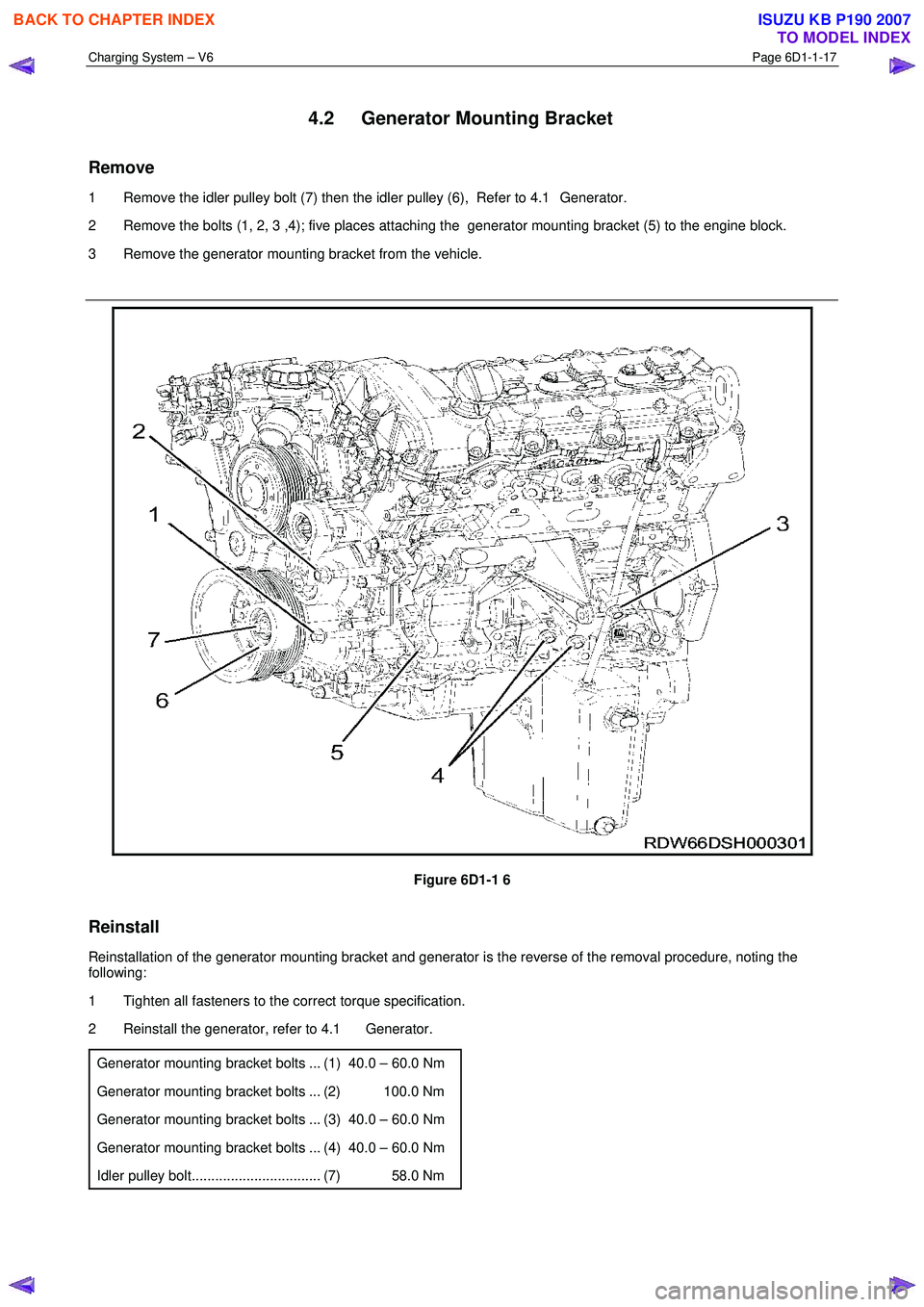
1 Remove the idler pulley bolt (7) then the idler pulley (6), Refer to 4.1 Generator.
2 Remove the bolts (1, 2, 3 ,4); five places attaching the generator mounting bracket (5) to the engine block.
3 Remove the generator mounting bracket from the vehicle.
Figure 6D1-1 6
Reinstall
Reinstallation of the generator mounting bracket and generator is the reverse of the removal procedure, noting the
following:
1 Tighten all fasteners to the correct torque specification.
2 Reinstall the generator, refer to 4.1 Generator.
Generator mounting bracket bolts ... (1) 40.0 – 60.0 Nm
Generator mounting bracket bolts ... (2) 100.0 Nm
Generator mounting bracket bolts ... (3) 40.0 – 60.0 Nm
Generator mounting bracket bolts ... (4) 40.0 – 60.0 Nm
Idler pulley bolt................................. (7) 58.0 Nm
BACK TO CHAPTER INDEX
TO MODEL INDEX
ISUZU KB P190 2007
Page 3628 of 6020

Starting System – V6 Page 6D1-2–20
6 Fit the rear lifting brackets: EN–46114 (1) to the
engine, then hook the chains from the engine hoist
onto the rear lifting bracket.
7 Remove the oil level indicator tube, Refer to 6A1 Engine Mechanical – V6.
Figure 6D1-2 – 9
8 Remove the left hand side knock sensor (1) from the engine block.
Figure 6D1-2 – 10
9 Remove the left hand side engine mount, then using the engine hoist raise the engine to give sufficient
clearance to remove the starter motor.
Figure 6D1-2 – 11
BACK TO CHAPTER INDEX
TO MODEL INDEX
ISUZU KB P190 2007
Page 3629 of 6020

Starting System – V6 Page 6D1-2–21
10 Unclip the oil level sensor harness from the heat shield
(1).
11 Remove the heat shield attaching screw (2).
12 Remove the lower starter motor attaching bolt (3).
13 Remove the heat shield.
14 Remove the upper starter motor retaining bolt (3).
15 Remove the starter motor from the engine block and lower the starter motor as far as possible to gain
access to the wiring harness connections.
Figure 6D1-2 – 12
16 Remove the wiring harness connector P – 3 (1) from the solenoid switch (2).
17 Remove the flange nut (3) and battery connector P – 4 (4) from the solenoid switch.
18 Remove the starter motor from the vehicle.
Figure 6D1-2 – 13
Reinstall
Reinstallation of the starter motor is the reverse of the removal procedure noting the following:
1 Tighten all fasteners to the correct torque specification.
Solenoid switch connector P – 4 nut (B+)
torque specification ............................................10.0 Nm
Starter motor heat shield lower bolts
torque specification ............................................23.0 Nm
Starter motor heat shield upper screw
torque specification .....................................3.0 – 5.0 Nm
Starter motor mounting bolt
torque specification ............................................45.0 Nm
Knock sensor bolt
torque specification ............................................23.0 Nm
2 Check the starter motor operates correctly.
BACK TO CHAPTER INDEX
TO MODEL INDEX
ISUZU KB P190 2007
Page 3674 of 6020
Powertrain Interface Module – V6 Page 6E1–13
3.2 Powertrain Interface Module Gateway
Components
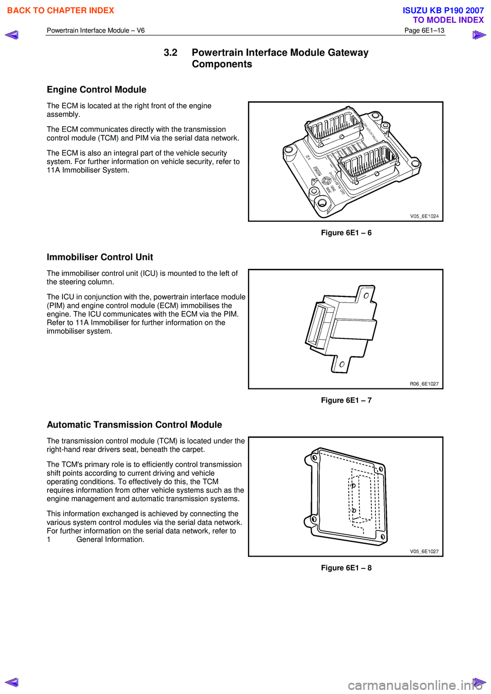
Engine Control Module
The ECM is located at the right front of the engine
assembly.
The ECM communicates directly with the transmission
control module (TCM) and PIM via the serial data network.
The ECM is also an integral part of the vehicle security
system. For further information on vehicle security, refer to
11A Immobiliser System.
Figure 6E1 – 6
Immobiliser Control Unit
The immobiliser control unit (ICU) is mounted to the left of
the steering column.
The ICU in conjunction with the, powertrain interface module
(PIM) and engine control module (ECM) immobilises the
engine. The ICU communicates with the ECM via the PIM.
Refer to 11A Immobiliser for further information on the
immobiliser system.
Figure 6E1 – 7
Automatic Transmission Control Module
The transmission control module (TCM) is located under the
right-hand rear drivers seat, beneath the carpet.
The TCM's primary role is to efficiently control transmission
shift points according to current driving and vehicle
operating conditions. To effectively do this, the TCM
requires information from other vehicle systems such as the
engine management and automatic transmission systems.
This information exchanged is achieved by connecting the
various system control modules via the serial data network.
For further information on the serial data network, refer to
1 General Information.
Figure 6E1 – 8
BACK TO CHAPTER INDEX
TO MODEL INDEX
ISUZU KB P190 2007
Page 3713 of 6020

Powertrain Interface Module – V6 Page 6E1–52
Step Action Yes No
4
Using a digital multimeter, measure the resistance between the VAS
earth circuit and a good ground. Refer to 6 W iring Diagram and
Connector Chart.
Does the multimeter display approximately 5.0 Ω?
Go to Step 5 Go to Step 8
5
1 Remove the VAS from its mounting bracket on the vehicle
chassis.
2 Switch on the ignition with the engine not running.
3 W hile rapidly moving the sensor in a vertical up and down motion, Use a digital multimeter to measure the voltage between
the VAS output signal circuit and a good ground.
Does the multimeter display 1.8 – 3.3 V? Go to Step 6 Go to Step 9
6 Perform the following VAS inspection:
• Inspect the sensor wiring harness for conditions that may induce
electromagnetic interference. Refer to Intermittent Fault
Conditions in this Section.
• Inspect the sensor for incorrect sensor installation or incorrect
attaching nut torque value. Refer to 11.3 Vertical
Acceleration Sensor.
W as any fault found and rectified? Go to Step 11 Go to Step 7
7
Test the VAS signal circuit and 5V reference circuit for a high
resistance, open circuit, short to ground, short to voltage or shorted
together fault condition. Refer to 8A Electrical - Body and Chassis for
information on electrical fault diagnosis.
W as any fault found and rectified? Go to Step 11 Go to Step 9
8
Repair the open or high resistance fault condition in the VAS ground
circuit. Refer to 8A Electrical - Body and Chassis for information on
electrical repair procedures.
W as the repair completed? Go to Step 11 —
9 Replace the VAS. Refer to 11.3 Vertical Acceleration Sensor.
W as the repair completed? Go to Step 11 —
10 Replace the PIM. Refer to 11.2 Powertrain Interface Module.
W as the repair completed? Go to Step 11 —
11 1 Using Tech 2, clear the DTCs.
2 Switch off the ignition for 30 seconds.
3 Start the engine.
4 Operate the vehicle within the conditions for running the DTC.
Does the VAS circuit DTC fail this ignition cycle? Go to Step 2 Go to Step 13
12
Using Tech 2, select the DTC display function.
Does Tech 2 display any DTCs? Go to the
appropriate DTC
Table in this Section System OK
When all diagnosis and repairs are completed, check the system for correct operation.
BACK TO CHAPTER INDEX
TO MODEL INDEX
ISUZU KB P190 2007