engine mount ISUZU KB P190 2007 Workshop Repair Manual
[x] Cancel search | Manufacturer: ISUZU, Model Year: 2007, Model line: KB P190, Model: ISUZU KB P190 2007Pages: 6020, PDF Size: 70.23 MB
Page 3960 of 6020
Automatic Transmission – 4L60E – On-vehicle Servicing Page 7C4–47
14 Reconnect the fuel and EVAP pipes three brackets and clips, refer to 6C Fuel System – V6.
15 Reinstall the following components:
a Starter motor, refer to 6D1-2 Starting System.
b Transmission support, refer to 3.7 Transmission Support and Mount.
c Front and centre exhaust assemblies, refer to 6F Exhaust System.
d Rear propeller shaft and for 4WD front propeller shaft, refer to 4A Propeller Shaft.
16 Reconnect the harness connectors to the following: a Vehicle speed sensor, refer to 3.5 Vehicle Speed Sensor.
b Neutral start and back-up switch, refer to 3.4 Neutral Start and Back-up Lamp Switch.
c For the following on 4W D vehicles, refer to 7D Transfer Case and Adaptor Housing:
• neutral switch,
• 2WD – 4WD shift actuator switch,
• speed sensor.
17 Reinstall the selector cable to the transmission external manual shaft linkage, secure the selector cable to the bracket and attach the heat shield to the neutral start and back-up lamp switch, refer to 3.3 Selector Cable
Assembly.
18 Perform a reverse flush of the cooler lines and a flow rate test, refer to 2.2 Reverse Flush and Flow Rate, if either of the following applies:
• the transmission fluid is contaminated,
• the transmission has been replaced,
• the torque converter has been replaced, or
• the transmission oil pump has been replaced.
19 Lower the vehicle to the ground.
20 If required, top up the transmission fluid level (cold).
21 Reconnect the battery ground lead.
22 Start the engine and check for any fluid leaking at the fittings. If a leak is found, stop the engine and rectify the leak.
23 Road test until the transmission has reached operating temperature. Re-check the fluid level and for any fluid leaks, refer to 2.1 Transmission Fluid.
3.19 Transmission Control Module
Remove
1 Ensure the ignition switch is in the OFF position.
2 Disconnect the connector (1) from the transmission control module (TCM) (2) as follows, refer to Figure 7C4 – 63: a remove the securing pin (3),
b press the locking tab and swing the lever (4) to free the connector,
c remove the connector.
3 Remove the four bolts (5) and nuts (6), then the TCM from the mounting bracket (7).
4 If required, remove the two nuts (8) and the mounting bracket from the firewall.
BACK TO CHAPTER INDEX
TO MODEL INDEX
ISUZU KB P190 2007
Page 4011 of 6020
TRANSMISSION CONTROL SYSTEM (AW30–40LE) 7A2-45
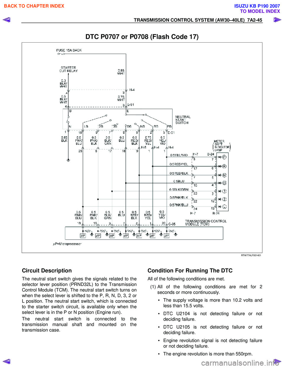
DTC P0707 or P0708 (Flash Code 17)
RTW 77ALF001401
Circuit Description
The neutral start switch gives the signals related to the
selector lever position (PRND32L) to the Transmission
Control Module (TCM). The neutral start switch turns on
when the select lever is shifted to the P, R, N, D, 3, 2 o
r
L position. The neutral start switch, which is connected
to the starter switch circuit, is available only when the
select lever is in the P or N position (Engine run).
The neutral start switch is connected to the
transmission manual shaft and mounted on the
transmission case.
Condition For Running The DTC
All of the following conditions are met.
(1) All of the following conditions are met for 2 seconds or more continuously.
• The supply voltage is more than 10.2 volts and
less than 15.5 volts.
• DTC U2104 is not detecting failure or not
deciding failure.
• DTC U2105 is not detecting failure or not
deciding failure.
• Engine revolution signal is not detecting failure
or not deciding failure.
• The engine revolution is more than 550rpm.
BACK TO CHAPTER INDEX
TO MODEL INDEX
ISUZU KB P190 2007
Page 4012 of 6020

7A2-46 TRANSMISSION CONTROL SYSTEM (AW30–40LE)
(2) Not emergency mode.
(3) All of the following conditions are met. • Device Control is not operating.
• Disable Normal Communication service is
receiving enable.
• DTC Clear is not operating.
Condition For Setting The DTC
DTC P0707
All of the following conditions are met for 30 seconds or
more continuously.
• All of the switches are “OFF”.
• Output revolution is more than 30 km/h (19 mph).
• Output revolution sensor is not detecting failure o
r
not deciding failure.
• The engine revolution is more than 1500 rpm.
DTC P0708
The following condition is met at 10 seconds
continuously.
• 2 switches or more are “ON” at the same time.
Action Taken When The DTC Sets
• No 3rd start mode.
• No slope control.
• No coast control.
• No output revolution sensor failure detection.
• No input revolution sensor failure detection.
• Keep oil temperature sensor OPEN failure detection accumulated timer.
• No T/F HI-Low SW failure detection.
• No shift solenoid functional failure detection.
• No L-up solenoid functional failure detection.
• No engine torque reduction at stall.
• Regard as D position. (DTC P0707)
• There is a priority in order of D, 3, 2, L, R, N, and P.
(DTC P0708)
• Check Trans “ON”.
• DTC stored.
• MIL request “ON”. (EURO 4 only)
Conditions For Clearing The DTC
•
The DTC can be cleared from the TCM history by
using a scan tool.
• The DTC will be cleared from history when the vehicle has achieved 40 warm-up cycles without a
failure reported.
•
After more than 1 second has elapsed after the
ignition key has been turned “ON”, short between
No.11 and No.4 (ground) of DLC (Data Link
Connector). Then, after 1 second, but within 6
seconds, discontinue shorting.
Diagnostic Aids
• Inspect the wiring for poor electrical connection at the
TCM. Look for possible bent, backed out, deformed
or damaged terminals. Check for weak terminal
tension as well. Also check for a chafed wire that
could short to bare metal or other wiring.
Inspect for a broken wire inside the insulation.
• W hen diagnosing for a possible intermittent short o
r
open condition, move the wiring harness while
observing test equipment for a change.
• Check neutral start switch for proper mounting and adjustment. (Refer to section 7A4 Components (1)
neutral start switch)
BACK TO CHAPTER INDEX
TO MODEL INDEX
ISUZU KB P190 2007
Page 4016 of 6020

7A2-50 TRANSMISSION CONTROL SYSTEM (AW30–40LE)
Action Taken When The DTC Sets
• Control at A/T oil temperature 80 °C (176 °F).
• No squat control.
• No slope control.
• No 3rd start mode.
• No line pressure reduction at gear change.
• No coast control.
• No line pressure reduction control at garage.
• No shift solenoid functional failure detection.
• No L-up solenoid functional failure detection.
• Check Trans “ON”.
• DTC stored.
• MIL request “ON”. (EURO 4 only)
Conditions For Clearing The DTC
• The DTC can be cleared from the TCM history by
using a scan tool.
• The DTC will be cleared from history when the vehicle has achieved 40 warm-up cycles without a
failure reported.
•
After more than 1 second has elapsed after the
ignition key has been turned “ON”, short between
No.11 and No.4 (ground) of DLC (Data Link
Connector). Then, after 1 second, but within 6
seconds, discontinue shorting.
Diagnostic Aids
•
Inspect the wiring for poor electrical connection at the
TCM. Look for possible bent, backed out, deformed
or damaged terminals. Check for weak terminal
tension as well. Also check for a chafed wire that
could short to bare metal or other wiring. Inspect for a
broken wire inside the insulation.
• W hen diagnosing for a possible intermittent short o
r
open condition, move the wiring harness while
observing test equipment for a change.
• Check oil temperature sensor for proper mounting and adjustment.
Circuit/System Testing DTC P0712
Step Action Value(s) YES NO
1
W as the On-Board Diagnostic (OBD) System Check
performed? — Go to
Step 2 Go to OBD
System Check
2 Perform the transmission fluid checking procedure. Refer to checking Transmission Fluid level and
Condition in Automatic Transmission 7A section.
W as the fluid checking procedure performed? — Go to
Step 3 Refer to
Checking
Transmission
Fluid level and Condition in Automatic
Transmission
(AW 30-40LE) section
3 1. Lift the driving wheels.
2. Start the engine and place the select lever in D
position.
3. W ait for 5 minutes.
Does a scan tool indicate DTC P0712? — Go to
Step 4 Refer to
Diagnostic Aids
BACK TO CHAPTER INDEX
TO MODEL INDEX
ISUZU KB P190 2007
Page 4019 of 6020

TRANSMISSION CONTROL SYSTEM (AW30–40LE) 7A2-53
• No L-up solenoid functional failure detection.
• Check Trans “ON”.
• DTC stored.
• MIL request “ON”. (EURO 4 only)
Conditions For Clearing The DTC
• The DTC can be cleared from the TCM history by
using a scan tool.
• The DTC will be cleared from history when the
vehicle has achieved 40 warm-up cycles without a
failure reported.
•
After more than 1 second has elapsed after the
ignition key has been turned “ON”, short between
No.11 and No.4 (ground) of DLC (Data Link
Connector). Then, after 1 second, but within 6
seconds, discontinue shorting.
Diagnostic Aids
•
Inspect the wiring for poor electrical connection at the
TCM. Look for possible bent, backed out, deformed
or damaged terminals. Check for weak terminal
tension as well. Also check for a chafed wire that
could short to bare metal or other wiring. Inspect for a
broken wire inside the insulation.
• W hen diagnosing for a possible intermittent short o
r
open condition, move the wiring harness while
observing test equipment for a change.
• Check oil temperature sensor for proper mounting
and adjustment.
Circuit/System Testing DTC P0713
Step Action Value(s) YES NO
1
W as the On-Board Diagnostic (OBD) System Check
performed ? — Go to
Step 2 Go to OBD
System check
2 Perform the transmission fluid checking procedure. Refer to Checking Transmission Fluid Level and
condition Automatic Transmission 7A section.
W as the fluid checking procedure performed? — Go to
Step 3 Refer to
checking
Transmission
Fluid Level and Condition
Automatic
Transmission
(AW 30-40LE) section
3 1. Lift the driving wheels.
2. Start the engine and place the select lever in D
position.
3. W ait for 15 minutes.
Does a scan tool indicate DTC P0713? — Go to
Step 4 Refer to
Diagnostic Aids
4 Observe the voltage of the oil temperature sensor on the Tech 2 data.
1. Turn “OFF” the ignition.
2. Disconnect the oil temperature sensor connector
E-83
3. Install a fused jumper wire from terminal E83-2 to E83-1 on the transmission harness.
4. Turn “ON” the ignition.
Does a scan tool indicate specified value? About 0V Go to
Step 5 Go to Step 6
5 Replace the transmission fluid temperature sensor.
If the action complete? — Go to
Step 9 —
BACK TO CHAPTER INDEX
TO MODEL INDEX
ISUZU KB P190 2007
Page 4095 of 6020

7A3-10 ON-VEHICLE SERVICE (AW30–40LE)
Measure Stall Speed
1. Chock the four wheels.
2. Mount an engine tachometer.
3. Fully apply the parking brake.
4. Step down strongly on the brake pedal with your left foot. (Keep the state until the test is completed)
5. Start the engine.
6. Turn off the A/C.
7. Select into the “D" position. Step all the way down on the accelerator pedal with your right foot. Quickl
y
record the highest speed as soon as the engine
speed gets stabilized.
8. Select into the “N” position and maintain the engine
idling condition more than 1 minute.
Stall speed: 2300 ±
±±
±
200 rpm *
* Ambient temperature to be between roughly 10 °C
(50 °F) and 40 °C (104 °F).
Evaluation
1. If the engine speed is the same for both positions
but lower than the specified value:
• Engine output is insufficient.
• Stator one-way clutch is not operating properly.
NOTE: If more than 600 rpm below the specified value,
the torque converter could be faulty.
2. If the stall speed in “D" position is higher than
specified:
• Line pressure too low
• Forward clutch slipping
• No.2 one-way clutch not operating properly
3. If the stall speed in “R" position is higher than
specified:
• Line pressure too low
• Direct clutch slipping
• No.3 brake slipping
4. If the stall speed in the “R" and “D" positions are
higher than specified:
• Line pressure too low
• Improper fluid level
Time Lag Test
F07RY00003
If the shift lever is shifted while the engine is idling,
there will be a certain time elapse or lag before the
shock can be felt. This is used for checking the
condition of the forward clutch, direct clutch, No.3
brake, and No.2 one-way clutch.
NOTE:
1. Perform the test at normal operating fluid
temperature (50 – 80 °C or 122 – 176 °F)
2. Be sure to allow one minute interval between tests.
3. Make three measurements and take the average value.
BACK TO CHAPTER INDEX
TO MODEL INDEX
ISUZU KB P190 2007
Page 4096 of 6020

ON-VEHICLE SERVICE (AW30–40LE) 7A3-11
Measure Time Lag
1. Fully apply the parking brake.
2. Start the engine. Check idling speed (A/C OFF).
3. Operate the select lever from “N" to “D" position.
Using a stopwatch, measure the time it takes from
shifting the lever until the shock is felt.
Time lag: Less than 0.7 seconds
4. In same manner, measure the time lag for “N" →
“R".
Time lag: Less than 1.2 seconds
Evaluation
1. If “N" → “D" time lag is longer than specified:
• Line pressure too low
• Forward clutch malfunction
• No.2 one-way clutch not operating properly
2. If “N" → “R" time lag is longer than specified:
• Line pressure too low
• Direct clutch malfunction
• First and Reverse brake malfunction
3. If both time lag is longer than specified:
• Line pressure too low
Hydraulic Test
RTW 67ALH000201
Preparation
1. W arm up the transmission fluid.
2. Remove the transmission case test plug and mount the hydraulic pressure gauge.
Oil pressure gauge: 5-8840-0093-0
NOTE: Perform the test at normal operating fluid
temperature (50 – 80 °C or 122 – 176 °F).
BACK TO CHAPTER INDEX
TO MODEL INDEX
ISUZU KB P190 2007
Page 4117 of 6020
7A3-32 ON-VEHICLE SERVICE (AW30–40LE)
Shift Solenoid and Lock-Up Solenoid
Removal
Preparation:
• Disconnect negative (–) battery cable.
• Drain the fluid.
Refer to ATF REPLACEMENT in this section.
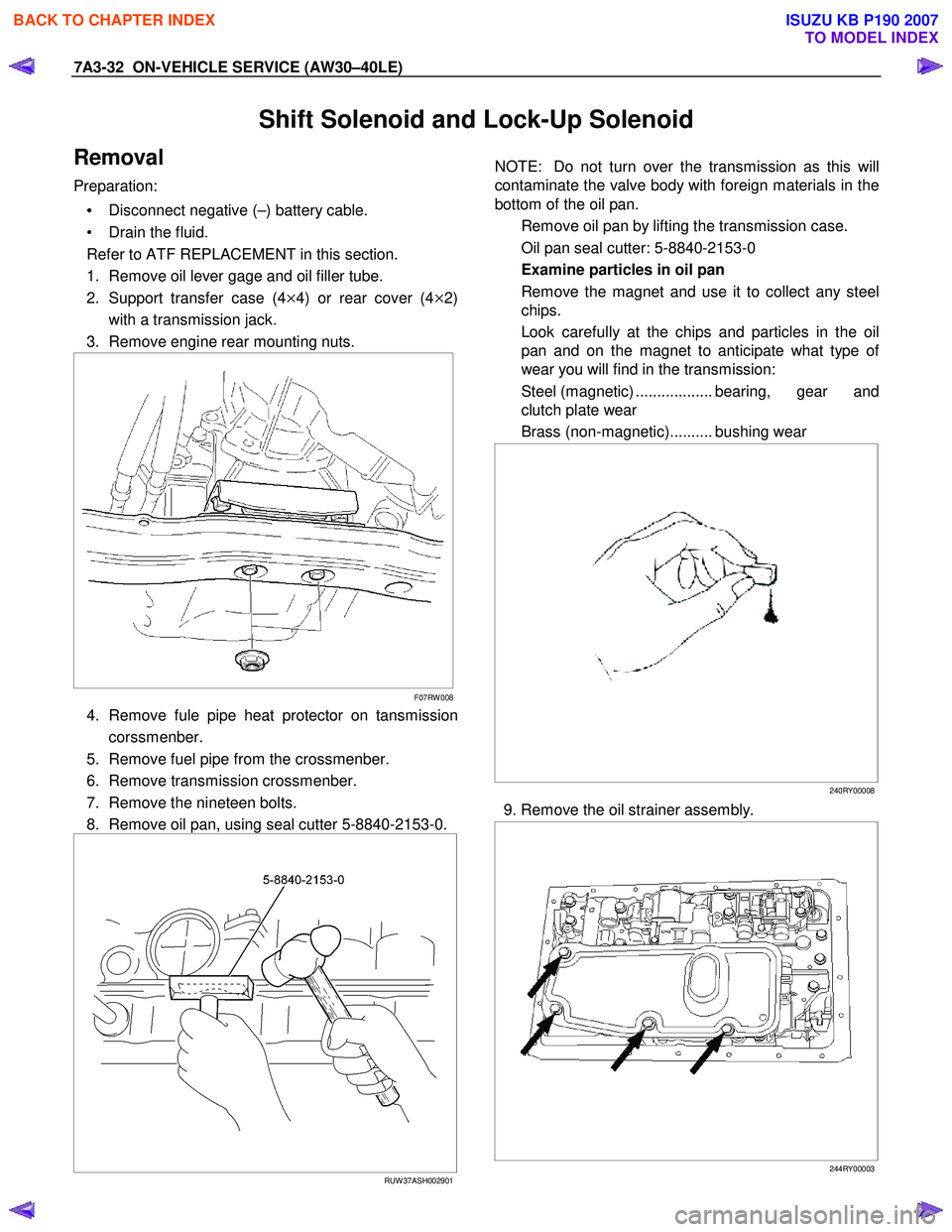
1. Remove oil lever gage and oil filler tube.
2. Support transfer case (4
×4) or rear cover (4×2)
with a transmission jack.
3. Remove engine rear mounting nuts.
F07RW 008
4. Remove fule pipe heat protector on tansmission
corssmenber.
5. Remove fuel pipe from the crossmenber.
6. Remove transmission crossmenber.
7. Remove the nineteen bolts.
8. Remove oil pan, using seal cutter 5-8840-2153-0.
RUW 37ASH002901
NOTE: Do not turn over the transmission as this will
contaminate the valve body with foreign materials in the
bottom of the oil pan.
Remove oil pan by lifting the transmission case.
Oil pan seal cutter: 5-8840-2153-0
Examine particles in oil pan
Remove the magnet and use it to collect any steel
chips.
Look carefully at the chips and particles in the oil
pan and on the magnet to anticipate what type o
f
wear you will find in the transmission:
Steel (magnetic) .................. bearing, gear and
clutch plate wear
Brass (non-magnetic).......... bushing wear
240RY00008
9. Remove the oil strainer assembly.
244RY00003
BACK TO CHAPTER INDEX
TO MODEL INDEX
ISUZU KB P190 2007
Page 4128 of 6020
ON-VEHICLE SERVICE (AW30–40LE) 7A3-43
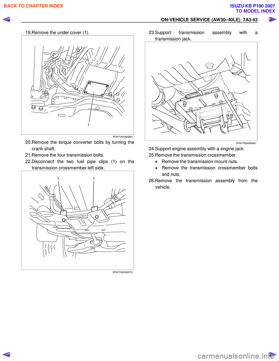
19.Remove the under cover (1).
RTW 77ASH002601
20.Remove the torque converter bolts by turning the
crank shaft.
21.Remove the four transmission bolts.
22.Disconnect the two fuel pipe clips (1) on the transmission crossmember left side.
RTW 77ASH002701
23.Support transmission assembly with a
transmission jack.
RTW 77BSH000401
24.Support engine assembly with a engine jack.
25.Remove the transmission crossmember. • Remove the transmission mount nuts.
• Remove the transmission crossmember bolts
and nuts.
26.Remove the transmission assembly from the vehicle.
BACK TO CHAPTER INDEX
TO MODEL INDEX
ISUZU KB P190 2007
Page 4129 of 6020
7A3-44 ON-VEHICLE SERVICE (AW30–40LE)
Installation
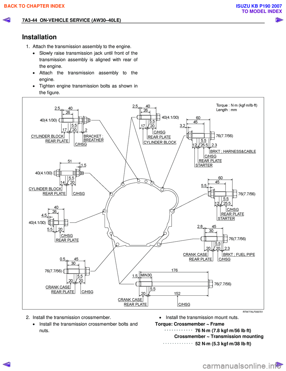
1. Attach the transmission assembly to the engine.
• Slowly raise transmission jack until front of the
transmission assembly is aligned with rear o
f
the engine.
•
Attach the transmission assembly to the
engine.
• Tighten engine transmission bolts as shown in
the figure.
RTW 77ALF000701
2. Install the transmission crossmember.
• Install the transmission crossmember bolts and
nuts.
• Install the transmission mount nuts.
Torque: Crossmember ∼
∼∼
∼
Frame
・
・・
・・
・・
・・
・・
・・
・・
・・
・・
・・
・・
・・
・・
・・
・・
・・
・・
・・
・・
・・
・・
・・
・・
・
76 N ⋅
⋅⋅
⋅
m (7.8 kgf ⋅m/56 lb ⋅ft)
Crossmember ∼
∼∼
∼
Transmission mounting
・・・・・・・・・・・・・
52 N⋅
⋅⋅
⋅
m (5.3 kgf ⋅m/38 lb ⋅ft)
BACK TO CHAPTER INDEX
TO MODEL INDEX
ISUZU KB P190 2007