recommended oil ISUZU KB P190 2007 Workshop Repair Manual
[x] Cancel search | Manufacturer: ISUZU, Model Year: 2007, Model line: KB P190, Model: ISUZU KB P190 2007Pages: 6020, PDF Size: 70.23 MB
Page 4 of 6020
0A-2 GENERAL INFORMATION
GENERAL REPAIR INSTRUCTIONS
1. Park the vehicle on level ground and chock the front or rear wheels before lifting the vehicle.
2. Raise the vehicle with a jack set against the axle or the frame.
3. Support the vehicle on chassis stands.
4. Use covers on the vehicle body, seats, and floor to prevent damage and/or contamination.
5. Disconnect the grounding cable from the battery before performing service operations.
This will prevent cable damage or burning due to short circuiting.
6. Handle brake fluid and antifreeze solution with great care.
Spilling these liquids on painted surfaces will damage the paint.
7. The use of the proper tool(s) and special tool(s) where specified is essential to efficient, reliable, and safe
service operations.
8. Always use genuine ISUZU replacement parts.
9. Discard used cotter pins, gaskets, O-rings, oil seals, lock washers, and self-locking nuts at disassembly.
Normal function of these parts cannot be guaranteed if they are reused.
10. Prepare new cotter pins, gaskets, O-rings, oil seals, lock washers, and self-locking nuts for installation.
11. Keep the disassembled parts neatly in groups. This will facilitate smooth and correct reassembly.
12. Keep fixing nuts and bolts separate. Fixing nuts and bolts vary in hardness and design according to installation position.
13. Clean all parts before inspection or reassembly.
14. Clean the oil ports and other openings with compressed air to make certain that they are free from dirt and obstructions.
15. Lubricate the rotating and sliding faces of all moving parts with oil or grease before installation.
16. Use the recommended liquid gasket to prevent leakage.
17. Carefully observe all nut and bolt torque specifications.
18. W hen removing or replacing parts that require refrigerant to the discharged from the air conditioning system, be sure to use the Vehicle Refrigerant Recovery and Recycling Equipment (VRRRE) to recover and recycle R134a,
to promote the aim of the protection of the ozone layer covering the earth.
19. Check and recheck your work. No service operation is complete until you have done this.
BACK TO CHAPTER INDEX
TO MODEL INDEX
ISUZU KB P190 2007
Page 5 of 6020
GENERAL INFORMATION 0A-3
NOTES ON THE FORMAT OF THIS MANUAL
1. Find the applicable section by referring to the index at the front of the W orkshop Manual binder.
2. The following technical service information is included in this Section: • Identification
• Maintenance schedules
• Recommended Iubricants
• Recommended fuels
• Oil viscosity charts
3. Individual sections of this W orkshop Manual are divided into the following categories: • Main data and specifications
• Torque specifications
• Recommended liquid gasket
• Loctite application procedure
• Servicing
• Removal and installation
• Disassembly
• Inspection and repair
• Reassembly
• Troubleshooting
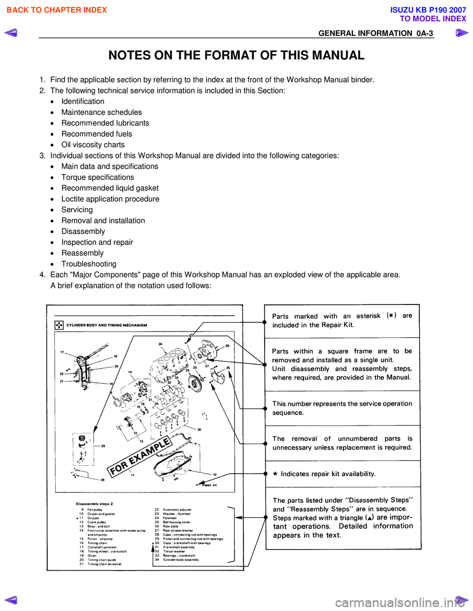
4. Each "Major Components" page of this W orkshop Manual has an exploded view of the applicable area.
A brief explanation of the notation used follows:
BACK TO CHAPTER INDEX
TO MODEL INDEX
ISUZU KB P190 2007
Page 6 of 6020
0A-4 GENERAL INFORMATION
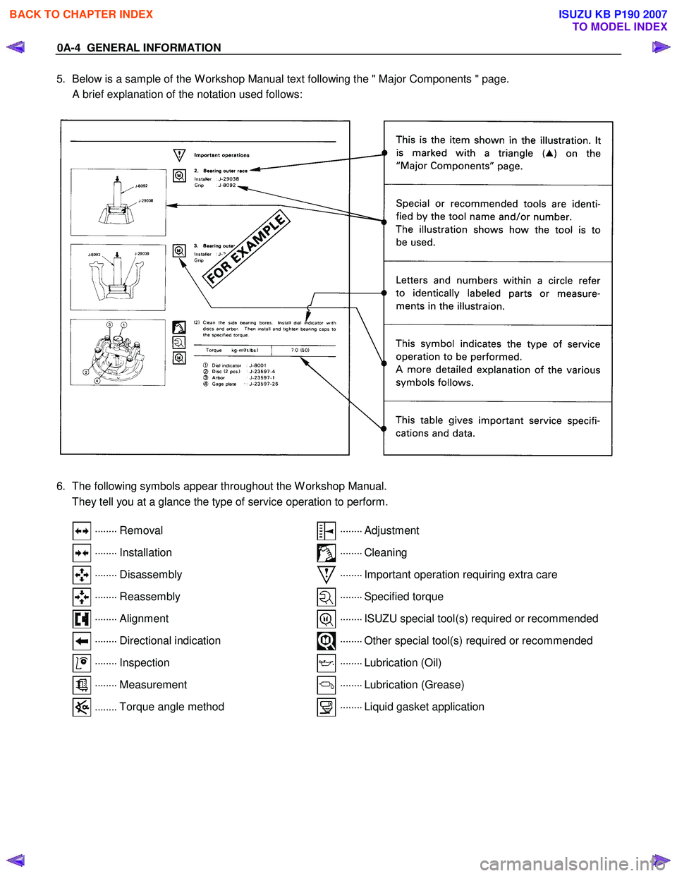
5. Below is a sample of the W orkshop Manual text following the " Major Components " page.
A brief explanation of the notation used follows:
6. The following symbols appear throughout the W orkshop Manual.
They tell you at a glance the type of service operation to perform.
........
Removal ........
Adjustment
........
Installation ........
Cleaning
........
Disassembly ........
Important operation requiring extra care
........
Reassembly ........
Specified torque
........
Alignment ........
ISUZU special tool(s) required or recommended
........
Directional indication ........
Other special tool(s) required or recommended
........
Inspection ........
Lubrication (Oil)
........
Measurement ........
Lubrication (Grease)
........
Torque angle method ........
Liquid gasket application
BACK TO CHAPTER INDEX
TO MODEL INDEX
ISUZU KB P190 2007
Page 19 of 6020
MAINTENANCE AND LUBRICATION 0B-1
SECTION 0B
MAINTENANCE AND LUBRICATION
TABLE OF CONTENTS
PAGE
Maintenance Schedule (For GENERAL EXPORT)......................................................... 0B- 2
Maintenance Schedule (For EUROPE)........................................................................... 0B- 5
Severe Conditions Maintenance Schedule (For GENERAL EXPORT) ........................ 0B- 9
Severe Conditions Maintenance Schedule (For EUROPE) .......................................... 0B-10
Recommended Fluids and Lubricants (For GENERAL EXPORT) ............................... 0B-11
Recommended Fluids and Lubricants (For EUROPE) ................................................. 0B-13
Oil Viscosity Chart........................................................................................................... 0B-14
BACK TO CHAPTER INDEX
TO MODEL INDEX
ISUZU KB P190 2007
Page 29 of 6020
MAINTENANCE AND LUBRICATION 0B-11
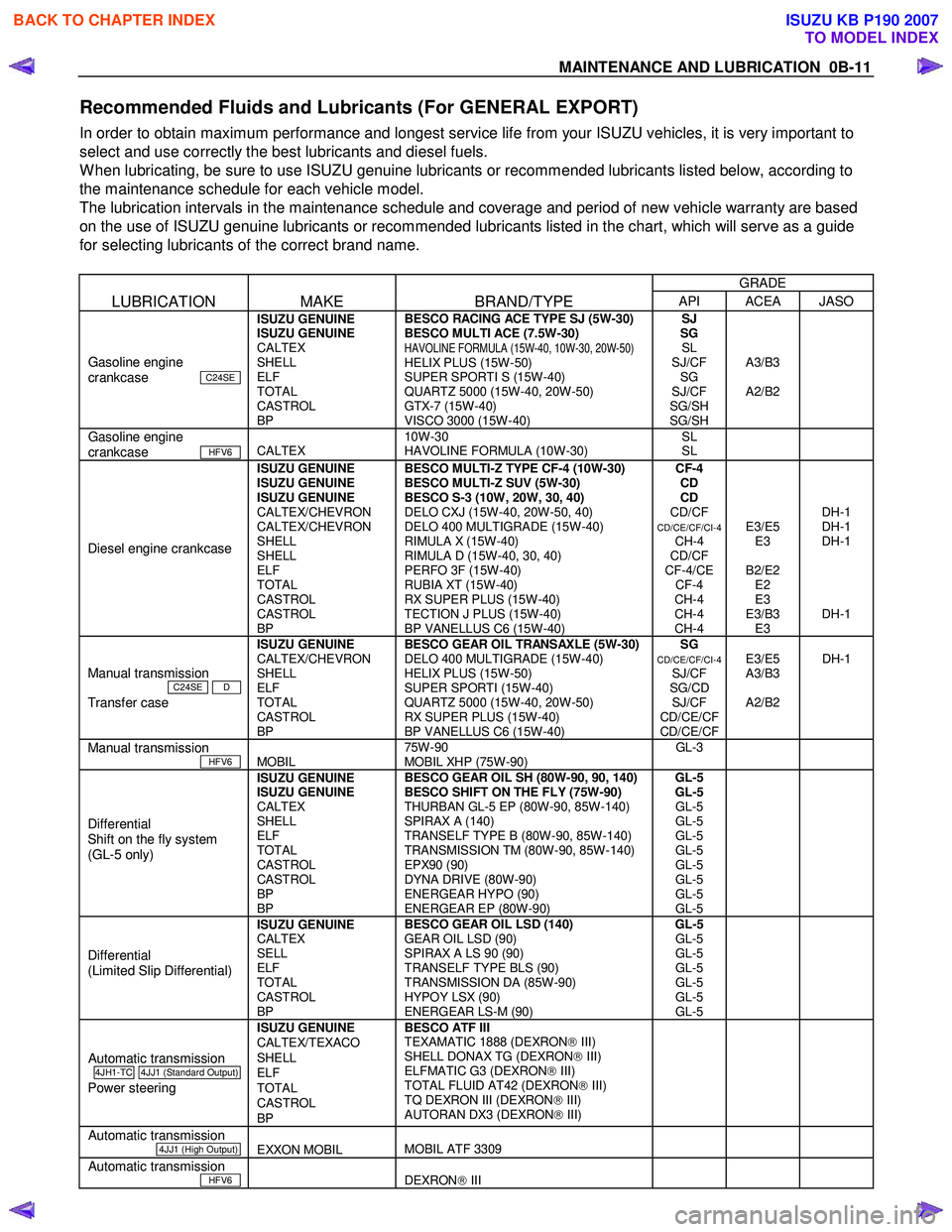
Recommended Fluids and Lubricants (For GENERAL EXPORT)
In order to obtain maximum performance and longest service life from your ISUZU vehicles, it is very important to
select and use correctly the best lubricants and diesel fuels.
W hen lubricating, be sure to use ISUZU genuine lubricants or recommended lubricants listed below, according to
the maintenance schedule for each vehicle model.
The lubrication intervals in the maintenance schedule and coverage and period of new vehicle warranty are based
on the use of ISUZU genuine lubricants or recommended lubricants listed in the chart, which will serve as a guide
for selecting lubricants of the correct brand name.
GRADE
LUBRICATION MAKE BRAND/TYPE API ACEA JASO
Gasoline engine
crankcase C24SE
ISUZU GENUINE
ISUZU GENUINE
CALTEX
SHELL
ELF
TOTAL
CASTROL
BP BESCO RACING ACE TYPE SJ (5W-30)
BESCO MULTI ACE (7.5W-30)
HAVOLINE FORMULA (15W-40, 10W-30, 20W-50) HELIX PLUS (15W-50)
SUPER SPORTI S (15W-40)
QUARTZ 5000 (15W-40, 20W-50)
GTX-7 (15W-40)
VISCO 3000 (15W-40) SJ
SG SL
SJ/CF SG
SJ/CF
SG/SH
SG/SH
A3/B3
A2/B2
Gasoline engine
crankcase HFV6
CALTEX 10W-30
HAVOLINE FORMULA (10W-30) SL
SL
Diesel engine crankcase
ISUZU GENUINE
ISUZU GENUINE
ISUZU GENUINE
CALTEX/CHEVRON
CALTEX/CHEVRON
SHELL
SHELL
ELF
TOTAL
CASTROL
CASTROL
BP BESCO MULTI-Z TYPE CF-4 (10W-30)
BESCO MULTI-Z SUV (5W-30)
BESCO S-3 (10W, 20W, 30, 40)
DELO CXJ (15W-40, 20W-50, 40)
DELO 400 MULTIGRADE (15W-40)
RIMULA X (15W-40)
RIMULA D (15W-40, 30, 40)
PERFO 3F (15W-40)
RUBIA XT (15W-40)
RX SUPER PLUS (15W-40)
TECTION J PLUS (15W-40)
BP VANELLUS C6 (15W-40) CF-4
CD
CD
CD/CF
CD/CE/CF/CI-4 CH-4
CD/CF
CF-4/CE CF-4
CH-4
CH-4
CH-4
E3/E5 E3
B2/E2 E2
E3
E3/B3 E3
DH-1
DH-1
DH-1
DH-1
Manual transmission
C24SE D
Transfer case
ISUZU GENUINE
CALTEX/CHEVRON
SHELL
ELF
TOTAL
CASTROL
BP
BESCO GEAR OIL TRANSAXLE (5W-30)
DELO 400 MULTIGRADE (15W-40)
HELIX PLUS (15W-50)
SUPER SPORTI (15W-40)
QUARTZ 5000 (15W-40, 20W-50)
RX SUPER PLUS (15W-40)
BP VANELLUS C6 (15W-40)
SG CD/CE/CF/CI-4 SJ/CF
SG/CD SJ/CF
CD/CE/CF
CD/CE/CF
E3/E5
A3/B3
A2/B2
DH-1
Manual transmission
HFV6
MOBIL 75W-90
MOBIL XHP (75W-90) GL-3
Differential
Shift on the fly system
(GL-5 only) ISUZU GENUINE
ISUZU GENUINE
CALTEX
SHELL
ELF
TOTAL
CASTROL
CASTROL
BP
BP BESCO GEAR OIL SH (80W-90, 90, 140)
BESCO SHIFT ON THE FLY (75W-90)
THURBAN GL-5 EP (80W-90, 85W-140)
SPIRAX A (140)
TRANSELF TYPE B (80W-90, 85W-140)
TRANSMISSION TM (80W-90, 85W-140)
EPX90 (90)
DYNA DRIVE (80W-90)
ENERGEAR HYPO (90)
ENERGEAR EP (80W-90) GL-5
GL-5 GL-5
GL-5
GL-5
GL-5
GL-5
GL-5
GL-5
GL-5
Differential
(Limited Slip Differential) ISUZU GENUINE
CALTEX
SELL
ELF
TOTAL
CASTROL
BP BESCO GEAR OIL LSD (140)
GEAR OIL LSD (90)
SPIRAX A LS 90 (90)
TRANSELF TYPE BLS (90)
TRANSMISSION DA (85W-90)
HYPOY LSX (90)
ENERGEAR LS-M (90) GL-5
GL-5
GL-5
GL-5
GL-5
GL-5
GL-5
Automatic transmission
4JH1-TC 4JJ1 (Standard Output)
Power steering
ISUZU GENUINE
CALTEX/TEXACO
SHELL
ELF
TOTAL
CASTROL
BP BESCO ATF III
TEXAMATIC 1888 (DEXRON III)
SHELL DONAX TG (DEXRON III)
ELFMATIC G3 (DEXRON III)
TOTAL FLUID AT42 (DEXRON III)
TQ DEXRON III (DEXRON III)
AUTORAN DX3 (DEXRON III)
Automatic transmission
4JJ1 (High Output)
EXXON MOBIL
MOBIL ATF 3309
Automatic transmission
HFV6
DEXRON III
BACK TO CHAPTER INDEX
TO MODEL INDEX
ISUZU KB P190 2007
Page 31 of 6020
MAINTENANCE AND LUBRICATION 0B-13
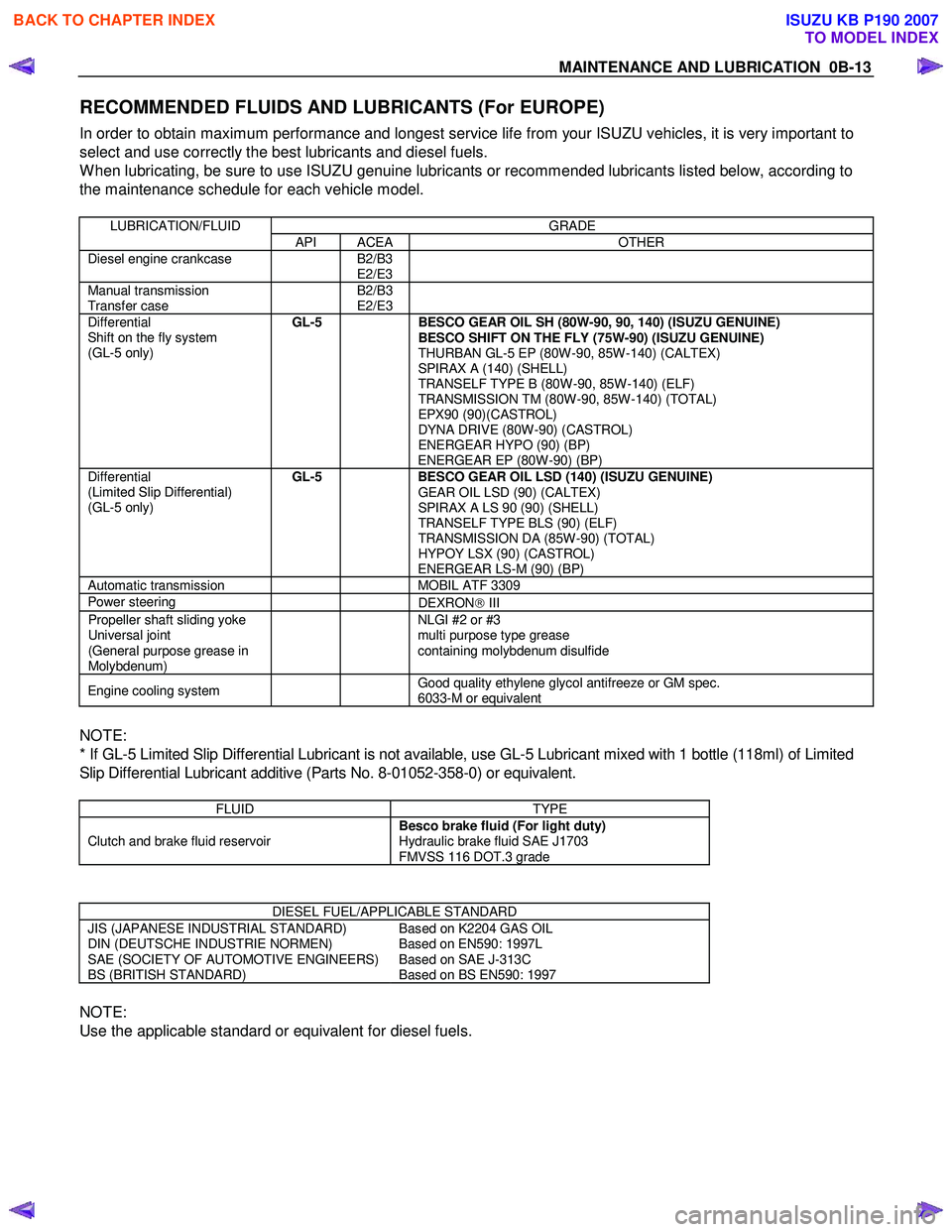
RECOMMENDED FLUIDS AND LUBRICANTS (For EUROPE)
In order to obtain maximum performance and longest service life from your ISUZU vehicles, it is very important to
select and use correctly the best lubricants and diesel fuels.
W hen lubricating, be sure to use ISUZU genuine lubricants or recommended lubricants listed below, according to
the maintenance schedule for each vehicle model.
LUBRICATION/FLUID GRADE
API ACEA OTHER
Diesel engine crankcase B2/B3
E2/E3
Manual transmission
Transfer case B2/B3
E2/E3
Differential
Shift on the fly system
(GL-5 only)
GL-5
BESCO GEAR OIL SH (80W-90, 90, 140) (ISUZU GENUINE)
BESCO SHIFT ON THE FLY (75W-90) (ISUZU GENUINE)
THURBAN GL-5 EP (80W-90, 85W-140) (CALTEX)
SPIRAX A (140) (SHELL)
TRANSELF TYPE B (80W-90, 85W-140) (ELF)
TRANSMISSION TM (80W-90, 85W-140) (TOTAL)
EPX90 (90)(CASTROL)
DYNA DRIVE (80W-90) (CASTROL)
ENERGEAR HYPO (90) (BP)
ENERGEAR EP (80W-90) (BP)
Differential
(Limited Slip Differential)
(GL-5 only) GL-5
BESCO GEAR OIL LSD (140) (ISUZU GENUINE)
GEAR OIL LSD (90) (CALTEX)
SPIRAX A LS 90 (90) (SHELL)
TRANSELF TYPE BLS (90) (ELF)
TRANSMISSION DA (85W-90) (TOTAL)
HYPOY LSX (90) (CASTROL)
ENERGEAR LS-M (90) (BP)
Automatic transmission MOBIL ATF 3309
Power steering
DEXRON III
Propeller shaft sliding yoke
Universal joint
(General purpose grease in
Molybdenum) NLGI #2 or #3
multi purpose type grease
containing molybdenum disulfide
Engine cooling system Good quality ethylene glycol antifreeze or GM spec.
6033-M or equivalent
NOTE:
* If GL-5 Limited Slip Differential Lubricant is not available, use GL-5 Lubricant mixed with 1 bottle (118ml) of Limited
Slip Differential Lubricant additive (Parts No. 8-01052-358-0) or equivalent.
FLUID TYPE
Clutch and brake fluid reservoir Besco brake fluid (For light duty)
Hydraulic brake fluid SAE J1703
FMVSS 116 DOT.3 grade
DIESEL FUEL/APPLICABLE STANDARD
JIS (JAPANESE INDUSTRIAL STANDARD)
DIN (DEUTSCHE INDUSTRIE NORMEN)
SAE (SOCIETY OF AUTOMOTIVE ENGINEERS)
BS (BRITISH STANDARD) Based on K2204 GAS OIL
Based on EN590: 1997L
Based on SAE J-313C
Based on BS EN590: 1997
NOTE:
Use the applicable standard or equivalent for diesel fuels.
BACK TO CHAPTER INDEX
TO MODEL INDEX
ISUZU KB P190 2007
Page 269 of 6020
3B-8 POWER-ASSISTED STEERING SYSTEM
6. Fully close the shutoff valve. Record the highest
pressures.
・ If the pressure recorded is within 9800-10300 kPa
(100-105 kg/cm
2/1422-1493psi), the pump is
functioning within its specifications.
・ If the pressure recorded is higher than 10300 kPa
(105 kg/cm
2/1493psi), the valve in the pump is
defective.
・ If the pressure recorded is lower than 9800 kPa
(100 kg/cm
2/1422psi), the valve or the rotating
assembly in the pump is defective.
7. If the pump pressures are within specifications, leave the valve open and turn (or have someone
else turn) the steering wheel fully in both directions.
Record the highest pressures and compare with the
maximum pump pressure recorded in step 6. If this
pressure cannot be built up at either side of the
power steering unit, the power steering unit is
leaking internally and must be replaced.
8. Shut the engine off, remove the testing gauge.
9. Reconnect the pressure hose, check the fluid level and make the needed repairs.
10. If the problem still exists, the steering and front suspension must be thoroughly examined.
Maintenance
The hydraulic system should be kept clean, the fluid
level in the reservoir should be checked at regula
r
intervals and fluid added when required. Refer to
Recommended Fluids and Lubricants in General
Information section for the type of fluid to be used and
the intervals for filling.
If the system contains some dirt, flush it as described in
this section. If it is exceptionally dirty, the pump must be
completely disassembled before further usage. (The
steering unit cannot be disassembled.)
All tubes, hoses, and fittings should be inspected for
leakage at regular intervals. Fittings must be tight. Make
sure the clips, clamps and supporting tubes and hoses
are in place and properly secured.
Power steering hoses and lines must not be twisted,
kinked or tightly bent. Air in the system will cause
spongy action and noisy operation. W hen a hose is
disconnected or when fluid is lost, for any reason, the
system must be bled after refilling. Refer to Bleeding the
Power Steering System in this section.
・ Inspect gear for looseness or damage.
・ Inspect hoses to insure they are not touching an
y
other parts of the vehicle.
・ Inspect fluid level and fill to the proper level.
Fluid Level
1. Run the engine until the power steering fluid
reaches normal operating temperature, about 55 °
C (130 °F), then shut the engine off.
2. Check the level of fluid in the reservoir.
3. If the fluid level is low, add power steering fluid as
specified in General Information to the proper level
and install the receiver cap.
4. W hen checking the fluid level after the steering system has been serviced, air must be bled from
the system. Refer to Bleeding the Power Steering
System in this section.
Bleeding the Power Steering System
W hen a power steering pump or unit has been installed,
or an oil line has been disconnected, the air that has
entered the system must be bled out before the vehicle
is operated. If air is allowed to remain in the powe
r
steering fluid system, noisy and unsatisfactory operation
of the system may result.
Bleeding Procedure
W hen bleeding the system, and any time fluid is added
to the power steering system, be sure to use only powe
r
steering fluid as specified in General Information.
1. Fill the pump fluid reservoir to the proper level and let the fluid settle for at least two minutes.
2. Start the engine and let it run for a few seconds. Do not turn the steering wheel. Then turn the engine
off.
3. Add fluid if necessary.
4. Repeat the above procedure until the fluid level remains constant after running the engine.
5. Raise and support the front end of the vehicle so that the wheels are off the ground.
6. Start the engine. Slowly turn the steering wheel right and left, lightly contacting the wheel stops.
7. Add power steering fluid if necessary.
8. Lower the vehicle, set the steering wheel at the straight forward position after turning it to its full
steer positions 2 or 3 times, and stop the engine.
9. Check the fluid level and refill as required.
10. If the fluid is extremely foamy, allow the vehicle to settle for a few minutes, then repeat the above
procedure.
Flushing the Power Steering System
1. Raise and support the front end of the vehicle off
the ground until the wheels are free to turn.
2. Remove the fluid return line at the pump inlet connector and plug the connector port on the pump.
Direct the line toward a large container to catch the
draining fluid.
3. W hile running the engine at idle, fill the reservoi
r
with new power steering fluid. Turn the steering
wheel in both directions. Do not contact or hold the
steering wheel to the wheel stops. This will cause
the pump to go to pressure relief mode, which ma
y
cause a sudden fluid overflow at the reservoir.
BACK TO CHAPTER INDEX
TO MODEL INDEX
ISUZU KB P190 2007
Page 799 of 6020
6 – 14 TROUBLESHOOTING
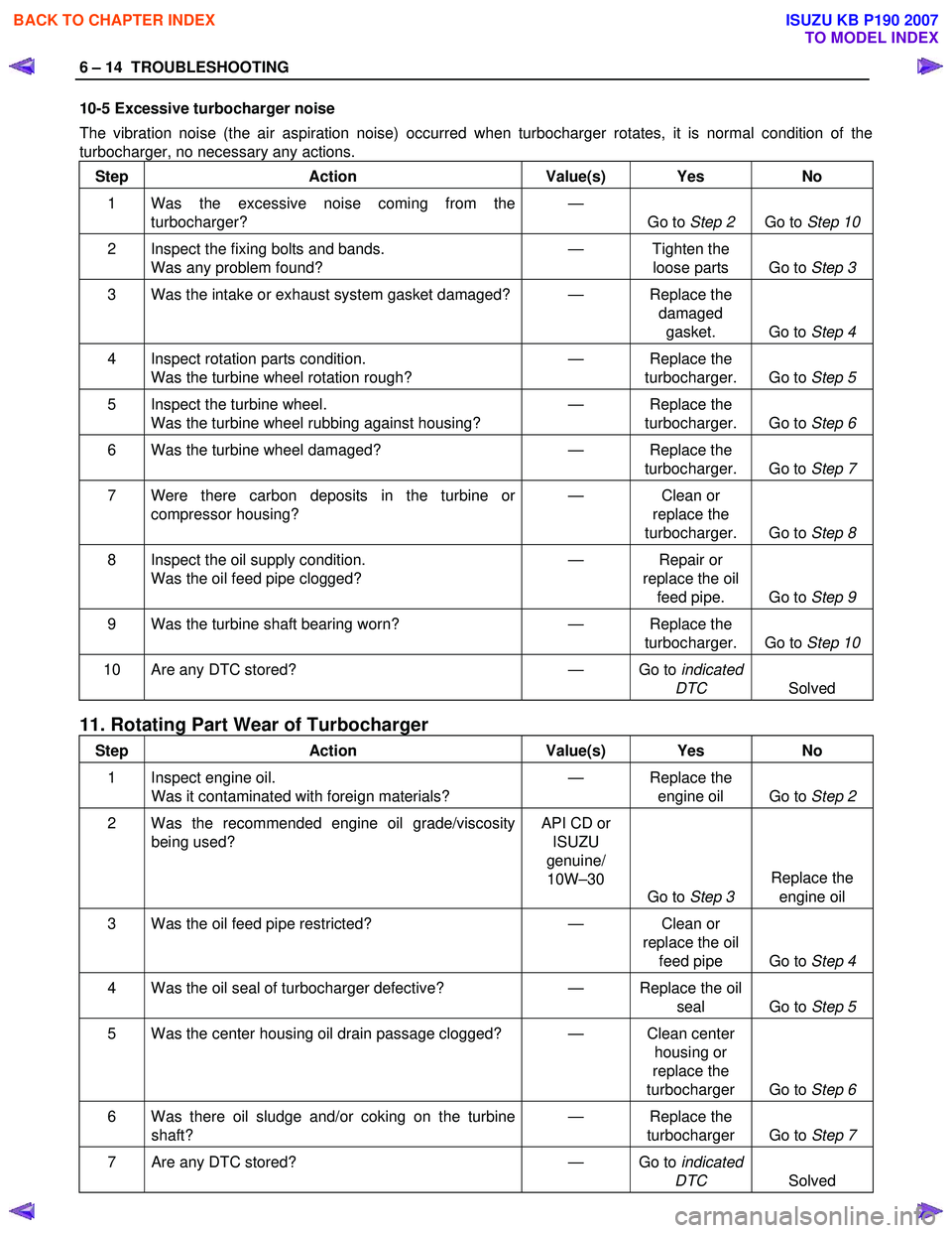
10-5 Excessive turbocharger noise
The vibration noise (the air aspiration noise) occurred when turbocharger rotates, it is normal condition of the
turbocharger, no necessary any actions.
Step Action Value(s) Yes No
1 Was the excessive noise coming from the turbocharger? —
Go to Step 2 Go to Step 10
2 Inspect the fixing bolts and bands.
Was any problem found? —
Tighten the
loose parts Go to Step 3
3 Was the intake or exhaust system gasket damaged? — Replace the
damaged gasket. Go to Step 4
4 Inspect rotation parts condition.
Was the turbine wheel rotation rough? —
Replace the
turbocharger. Go to Step 5
5 Inspect the turbine wheel.
Was the turbine wheel rubbing against housing? —
Replace the
turbocharger. Go to Step 6
6 Was the turbine wheel damaged? — Replace the
turbocharger. Go to Step 7
7 Were there carbon deposits in the turbine or
compressor housing? —
Clean or
replace the
turbocharger. Go to Step 8
8 Inspect the oil supply condition.
Was the oil feed pipe clogged? —
Repair or
replace the oil feed pipe. Go to Step 9
9 Was the turbine shaft bearing worn? — Replace the
turbocharger. Go to Step 10
10 Are any DTC stored? — Go to indicated
DTC Solved
11. Rotating Part Wear of Turbocharger
Step Action Value(s) Yes No
1 Inspect engine oil.
Was it contaminated with foreign materials? —
Replace the
engine oil Go to Step 2
2 Was the recommended engine oil grade/viscosity
being used? API CD or
ISUZU
genuine/ 10W –30
Go to Step 3 Replace the
engine oil
3 Was the oil feed pipe restricted? — Clean or
replace the oil feed pipe Go to Step 4
4 Was the oil seal of turbocharger defective? — Replace the oil
seal Go to Step 5
5 Was the center housing oil drain passage clogged? — Clean center
housing or
replace the
turbocharger Go to Step 6
6 Was there oil sludge and/or coking on the turbine
shaft? —
Replace the
turbocharger Go to Step 7
7 Are any DTC stored? — Go to indicated
DTC Solved
BACK TO CHAPTER INDEX
TO MODEL INDEX
ISUZU KB P190 2007
Page 830 of 6020
ENGINE MECHANICAL 6A – 25
Replenished Engine Oil MAX lit (US/UK gal)
Condition
Model Engine Dry
W ith oil filter
replacement W ithout oil
filter
replacement
4 × 2
4 × 4
(4JA1L/TC)6.2 (1.64/1.36) 5.2 ∼ 4.2
(1.37 ∼ 1.11
/ 1.14 ∼ 0.92) 4.5
∼ 3.5
(1.19 ∼ 0.93
/ 0.99 ∼ 0.77)
4 × 2
(4JH1TC)
6.2 (1.64/1.36) 5.2
∼ 4.2
(1.37 ∼ 1.11
/ 1.14 ∼ 0.92) 4.5
∼ 3.5
(1.19 ∼ 0.93
/ 0.99 ∼ 0.77)
4 × 4
(4JH1TC) 7.0 (1.85/1.54) 6.2 ∼ 5.2
(1.64 ∼ 1.37
/ 1.36 ∼ 1.14) 5.3
∼ 4.3
(1.72 ∼ 1.14
/ 1.17 ∼ 0.95)
9. Start the engine and check for oil leakage from the
main oil filter.
RTW 66ASH003201
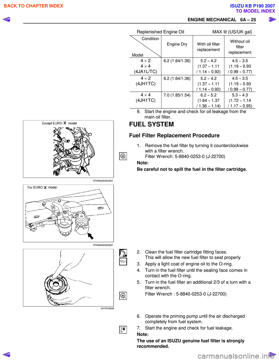
FUEL SYSTEM
Fuel Filter Replacement Procedure
1. Remove the fuel filter by turning it counterclockwise with a filter wrench.
Filter W rench: 5-8840-0253-0 (J-22700)
Note:
Be careful not to spill the fuel in the filter cartridge.
RTW 66ASH003301
2. Clean the fuel filter cartridge fitting faces. This will allow the new fuel filter to seat properly
3. Apply a light coat of engine oil to the O-ring.
4. Turn in the fuel filter until the sealing face comes in contact with the O-ring.
5. Turn in the fuel filter an additional 2/3 of a turn with a filter wrench.
Filter W rench : 5-8840-0253-0 (J-22700)
6. Operate the priming pump until the air discharged completely from fuel system.
7. Start the engine and check for fuel leakage.
Note:
The use of an ISUZU genuine fuel filter is strongly
recommended.
041RY00009
BACK TO CHAPTER INDEX
TO MODEL INDEX
ISUZU KB P190 2007
Page 910 of 6020

ENGINE MECHANICAL 6A – 105
5. Crankshaft Thrust Bearing
Apply an ample coat of engine oil to the thrust bearings
before installation.
Install the thrust bearings to the crankshaft center journal.
The thrust bearing oil grooves must be facing the sliding
faces.
6. Crankshaft Bearing Cap With Lower Bearing
Before the crankshaft bearing installation, select the
appropriate bearings in accordance with the description in
CRANK BEARING SELECTION of INSPECTION AND
REPAIR.
1. Apply the recommended liquid gasket or its equivalent to the No. 5 crankshaft bearing cap cylinder body fitting
surfaces at the points shown in the illustration.
NOTE:
Be sure that the bearing cap fitting surface is
completely free of oil before applying the liquid
gasket. Three bond 1207B Do not allow the liquid
gasket to obstruct the cylinder thread holes and
bearings.
ThreeBond 1207B is a fast-drying liquid gasket.
Tighten the bearing caps immediately after applying
the gasket.
2. Install the bearing caps with the bearing cap head
arrow mark facing the front of the engine.The bearing
cap numbers must be facing up.
3. Apply engine oil to the crankshaft bearing cap bolts.
4. Tighten the crankshaft bearing cap bolts to the
specified torque a little at time in the sequence shown
in the illustration.
Crankshaft Bearing Cap Torque N·m(kg·m/lbft)
167 (17/123)
5. Check to see the crankshaft turns smoothly by rotating it manually.
015LX115
015LX127
015LX128
015LX129
BACK TO CHAPTER INDEX
TO MODEL INDEX
ISUZU KB P190 2007