oil dipstick ISUZU KB P190 2007 Workshop Repair Manual
[x] Cancel search | Manufacturer: ISUZU, Model Year: 2007, Model line: KB P190, Model: ISUZU KB P190 2007Pages: 6020, PDF Size: 70.23 MB
Page 2013 of 6020

ENGINE DIAGNOSIS (C24SE) 6-13
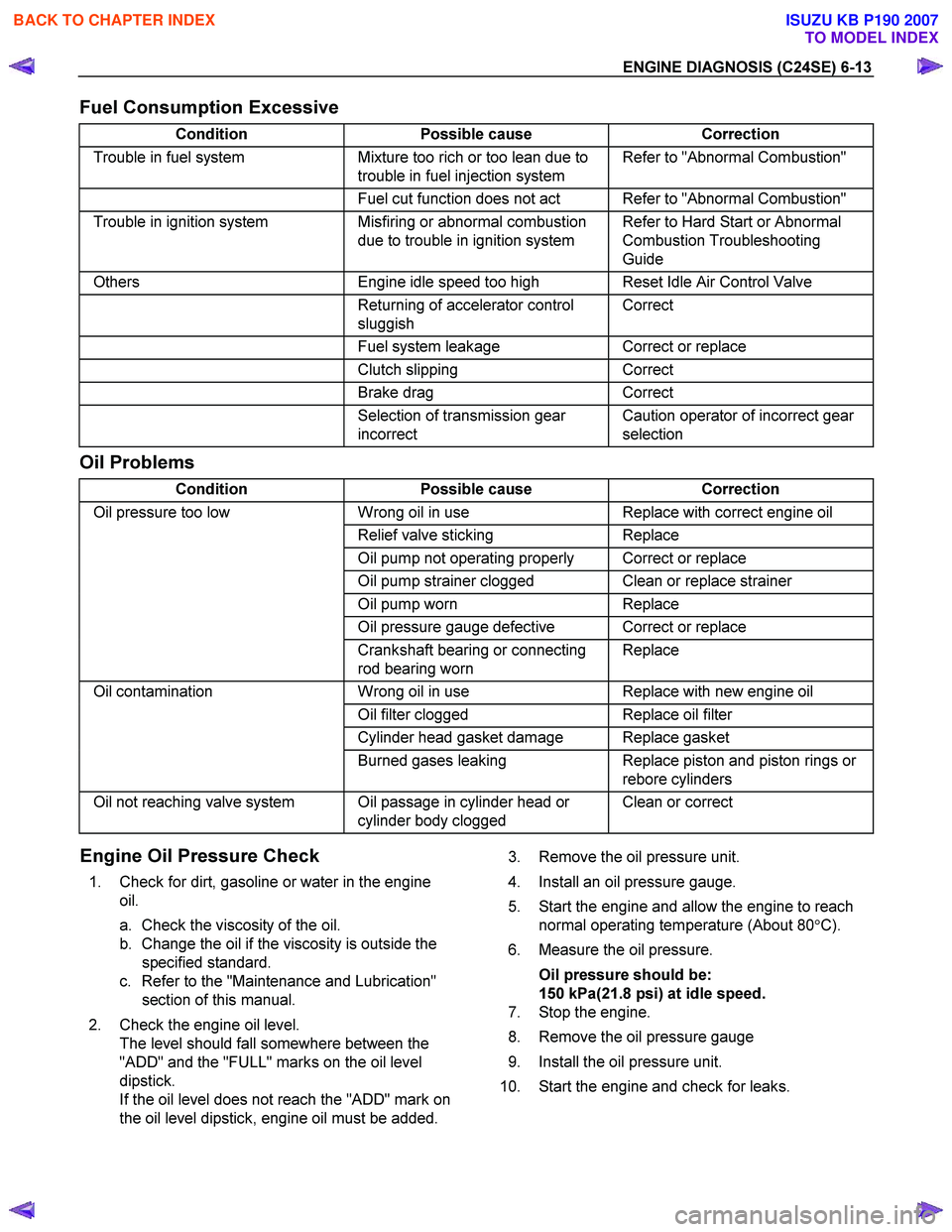
Fuel Consumption Excessive
Condition Possible cause Correction
Trouble in fuel system Mixture too rich or too lean due to
trouble in fuel injection system Refer to "Abnormal Combustion"
Fuel cut function does not act Refer to "Abnormal Combustion"
Trouble in ignition system Misfiring or abnormal combustion
due to trouble in ignition system Refer to Hard Start or Abnormal
Combustion Troubleshooting
Guide
Others Engine idle speed too high Reset Idle Air Control Valve
Returning of accelerator control
sluggish Correct
Fuel system leakage Correct or replace
Clutch slipping Correct
Brake drag Correct
Selection of transmission gear
incorrect Caution operator of incorrect gear
selection
Oil Problems
Condition Possible cause Correction
Oil pressure too low Wrong oil in use Replace with correct engine oil
Relief valve sticking Replace
Oil pump not operating properly Correct or replace
Oil pump strainer clogged Clean or replace strainer
Oil pump worn Replace
Oil pressure gauge defective Correct or replace
Crankshaft bearing or connecting
rod bearing worn Replace
Oil contamination
Wrong oil in use Replace with new engine oil
Oil filter clogged Replace oil filter
Cylinder head gasket damage Replace gasket
Burned gases leaking Replace piston and piston rings or
rebore cylinders
Oil not reaching valve system Oil passage in cylinder head or cylinder body clogged Clean or correct
Engine Oil Pressure Check
1. Check for dirt, gasoline or water in the engine
oil.
a. Check the viscosity of the oil.
b. Change the oil if the viscosity is outside the specified standard.
c. Refer to the "Maintenance and Lubrication" section of this manual.
2. Check the engine oil level. The level should fall somewhere between the
"ADD" and the "FULL" marks on the oil level
dipstick.
If the oil level does not reach the "ADD" mark on
the oil level dipstick, engine oil must be added.
3. Remove the oil pressure unit.
4. Install an oil pressure gauge.
5. Start the engine and allow the engine to reach normal operating temperature (About 80 °C).
6. Measure the oil pressure.
Oil pressure should be:
150 kPa(21.8 psi) at idle speed.
7. Stop the engine.
8. Remove the oil pressure gauge
9. Install the oil pressure unit.
10. Start the engine and check for leaks.
BACK TO CHAPTER INDEX
TO MODEL INDEX
ISUZU KB P190 2007
Page 2091 of 6020

ENGINE MECHANICAL (C24SE) 6A-77
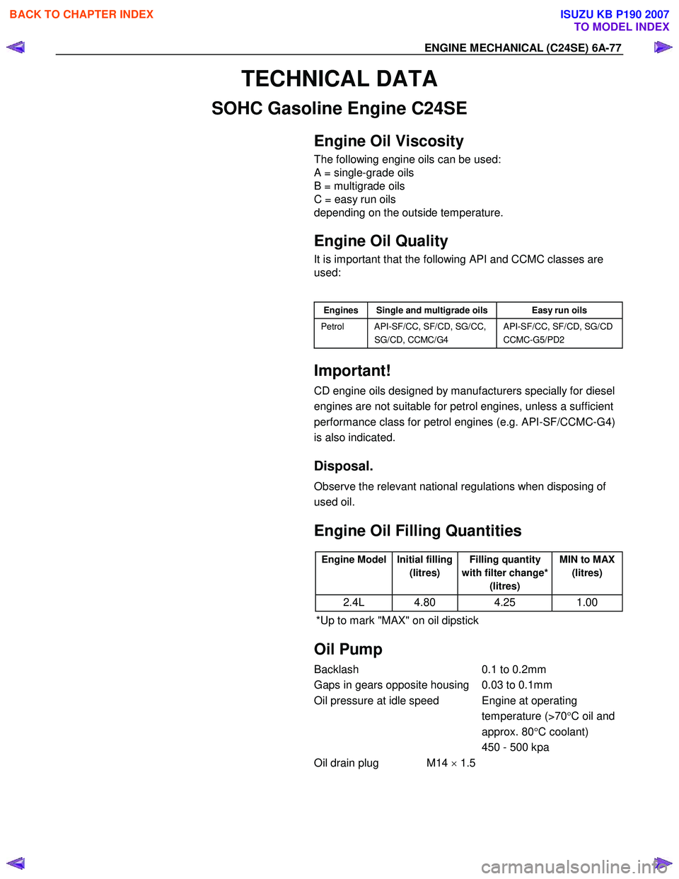
TECHNICAL DATA
SOHC Gasoline Engine C24SE
Engine Oil Viscosity
The following engine oils can be used:
A = single-grade oils
B = multigrade oils
C = easy run oils
depending on the outside temperature.
Engine Oil Quality
It is important that the following API and CCMC classes are
used:
Engines Single and multigrade oils Easy run oils
Petrol API-SF/CC, SF/CD, SG/CC,
SG/CD, CCMC/G4 API-SF/CC, SF/CD, SG/CD
CCMC-G5/PD2
Important!
CD engine oils designed by manufacturers specially for diesel
engines are not suitable for petrol engines, unless a sufficient
performance class for petrol engines (e.g. API-SF/CCMC-G4)
is also indicated.
Disposal.
Observe the relevant national regulations when disposing of
used oil.
Engine Oil Filling Quantities
Engine Model Initial filling
(litres) Filling quantity
with filter change* (litres) MIN to MAX
(litres)
2.4L 4.80 4.25 1.00
*Up to mark "MAX" on oil dipstick
Oil Pump
Backlash 0.1 to 0.2mm
Gaps in gears opposite housing 0.03 to 0.1mm
Oil pressure at idle speed Engine at operating temperature (>70°C oil and
approx. 80 °C coolant)
450 - 500 kpa
Oil drain plug M14 × 1.5
BACK TO CHAPTER INDEX
TO MODEL INDEX
ISUZU KB P190 2007
Page 3168 of 6020

Engine Cooling – V6 Engine Page 6B1–33
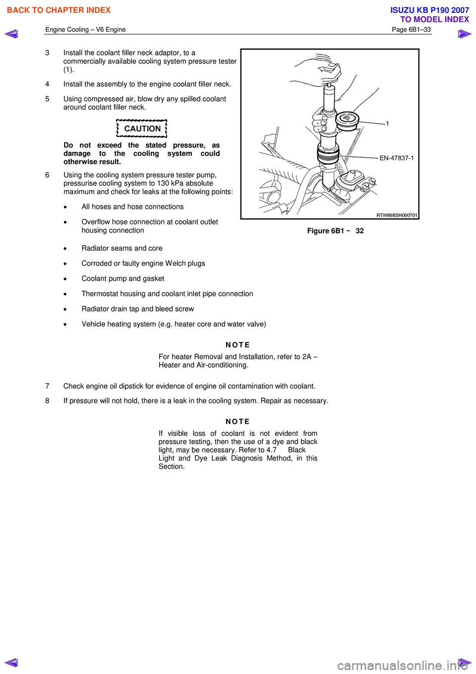
3 Install the coolant filler neck adaptor, to a
commercially available cooling system pressure tester
(1).
4 Install the assembly to the engine coolant filler neck.
5 Using compressed air, blow dry any spilled coolant around coolant filler neck.
Do not exceed the stated pressure, as
damage to the cooling system could
otherwise result.
6 Using the cooling system pressure tester pump, pressurise cooling system to 130 kPa absolute
maximum and check for leaks at the following points:
• All hoses and hose connections
• Overflow hose connection at coolant outlet
housing connection
Figure 6B1 –
––
–
32
• Radiator seams and core
• Corroded or faulty engine W elch plugs
• Coolant pump and gasket
• Thermostat housing and coolant inlet pipe connection
• Radiator drain tap and bleed screw
• Vehicle heating system (e.g. heater core and water valve)
NOTE
For heater Removal and Installation, refer to 2A –
Heater and Air-conditioning.
7 Check engine oil dipstick for evidence of engine oil contamination with coolant.
8 If pressure will not hold, there is a leak in the cooling system. Repair as necessary.
NOTE
If visible loss of coolant is not evident from
pressure testing, then the use of a dye and black
light, may be necessary. Refer to 4.7 Black
Light and Dye Leak Diagnosis Method, in this
Section.
BACK TO CHAPTER INDEX
TO MODEL INDEX
ISUZU KB P190 2007
Page 3349 of 6020

Engine Management – V6 – Diagnostics Page 6C1-2–71
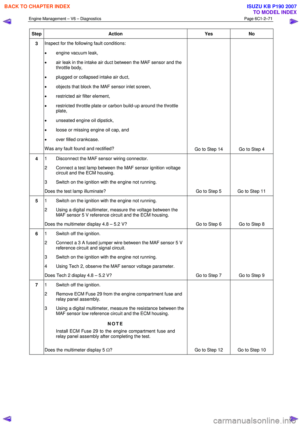
Step Action Yes No
3 Inspect for the following fault conditions:
• engine vacuum leak,
• air leak in the intake air duct between the MAF sensor and the
throttle body,
• plugged or collapsed intake air duct,
• objects that block the MAF sensor inlet screen,
• restricted air filter element,
• restricted throttle plate or carbon build-up around the throttle
plate,
• unseated engine oil dipstick,
• loose or missing engine oil cap, and
• over filled crankcase.
W as any fault found and rectified? Go to Step 14 Go to Step 4
4 1 Disconnect the MAF sensor wiring connector.
2 Connect a test lamp between the MAF sensor ignition voltage circuit and the ECM housing.
3 Switch on the ignition with the engine not running.
Does the test lamp illuminate? Go to Step 5 Go to Step 11
5 1 Switch on the ignition with the engine not running.
2 Using a digital multimeter, measure the voltage between the MAF sensor 5 V reference circuit and the ECM housing.
Does the multimeter display 4.8 – 5.2 V? Go to Step 6 Go to Step 8
6 1 Switch off the ignition.
2 Connect a 3 A fused jumper wire between the MAF sensor 5 V reference circuit and signal circuit.
3 Switch on the ignition with the engine not running.
4 Using Tech 2, observe the MAF sensor voltage parameter.
Does Tech 2 display 4.8 – 5.2 V? Go to Step 7 Go to Step 9
7 1 Switch off the ignition.
2 Remove ECM Fuse 29 from the engine compartment fuse and relay panel assembly.
3 Using a digital multimeter, measure the resistance between the MAF sensor low reference circuit and the ECM housing.
NOTE
Install ECM Fuse 29 to the engine compartment fuse and
relay panel assembly after completing the test.
Does the multimeter display 5 Ω? Go to Step 12 Go to Step 10
BACK TO CHAPTER INDEX
TO MODEL INDEX
ISUZU KB P190 2007
Page 4104 of 6020

ON-VEHICLE SERVICE (AW30–40LE) 7A3-19
ATF Replacement
Inspection
NOTE: Do not overfill.
1. Remove the drain plug from oil pan and drain the
fluid.
RUW 17ASH013401
2. Reinstall the drain plug securely.
Torque: 19 N ⋅
⋅⋅
⋅
m (1.9 kgf ⋅
⋅⋅
⋅
m/14 Ib ⋅
⋅⋅
⋅
ft)
3. W ith the engine OFF, add new fluid through the fille
r
tube.
Drain and refill 5.2 liter
Dry fill 8.7 liter
Fluid Exxon Mobil ATF-3309
4. Start the engine and shift the selector into all
position from “P" through “L", and then shift into “P".
5. W ith the engine idling, check the fluid level. Add fluid up to the “COLD" level on the dipstick.
6. The ATF level must be checked again for correct level with the “HOT" level.
NOTE: To prevent fluid leaks, the drain plug gasket
must be replaced each time this plug is removed.
BACK TO CHAPTER INDEX
TO MODEL INDEX
ISUZU KB P190 2007
Page 4457 of 6020

ON-VEHICLE SERVICE (JR405E) 7A3-3
Cold Level
The vehicle must not have been driven so that the
temperature reaches around 20 °C (68 °F) before the
cold level check is made.
1. Park the vehicle on a level surface.
2. Apply the parking brake firmly.
3. Start the engine and allow it to warm up.
The engine coolant temperature gauge needle should be midway between the “C” mark and “H”
mark.
4. Let the engine run at idle.
Move the select lever slowly through all the gea
r
ranges.
Stop in each range just long enough for the transmission to engage.
5. Return the select lever either “P” or “N”.
6. Remove the ATF level dipstick.
7. W ipe the dipstick clean with a paper towel.
8. Reinsert the dipstick and wait several seconds.
9. Remove the dipstick.
The ATF level should be inside the “C” range on the dipstick.
If the ATF level is below the “C” range, ATF must be added.
242R300002
ATF CHANGE
1. Park the vehicle on level ground and block the rear
wheels.
2. Start the engine and allow it to idle until the ATF reaches a temperature of 40-50 °C (104-122 °F).
3. Stop the engine.
4. Raise the front to the vehicle and support with suitable safety stands.
5. Remove the drain plug from the oil pan and drain the ATF (approximately 6 liters).
6. Remove the oil pan.
7. Inspect the oil pan (details written below).
8. Install the oil pan.
Note:
Use a new gasket. Clean the oil pan and magnet.
Oil pan bolt torque : 8 N ⋅m (0.8 kgf ⋅m/69 lb ⋅in)
9. Replace the gasket and install the drain plug.
Drain plug torque : 35 N ⋅m (3.6 kgf ⋅m/26 lb ⋅ft)
Note:
Do not reuse the old washer (gasket).
Clean the drain plug (especially the threaded section).
10.Remove the safety stands and wheel blocks.
11.Pour about 5 liters of new ATF.
12. Start the engine. W ith your foot on the brake, move the shift lever through each gear range, and shift to
“P” range.
13.Check the ATF level. Add more ATF carefully as necessary using the dipstick. Refer to “ATF LEVEL”
preciously in this section.
Note:
Keep the engine idle (do not stop it) during the ATF level
adjustment.
BACK TO CHAPTER INDEX
TO MODEL INDEX
ISUZU KB P190 2007