automatic transmission fluid ISUZU KB P190 2007 Workshop Owner's Guide
[x] Cancel search | Manufacturer: ISUZU, Model Year: 2007, Model line: KB P190, Model: ISUZU KB P190 2007Pages: 6020, PDF Size: 70.23 MB
Page 3793 of 6020

Automatic Transmission – 4L60E – Electrical Diagnosis Page 7C2–7
DTC P2770 Diagnostic Table............................................................................................................................. 120
4.37 DTC U0073 and U0100 – CAN-Bus No Communication With ECM (Engine Control Module)...................... 121
DTC Description ................................................................................................................................................. 121
Circuit Description ............................................................................................................................................. 121
Conditions for Running the DTC ................................................................................................. ..................... 121
Conditions for Setting the DTC......................................................................................................................... 121
DTC U0073 .................................................................................................................................................... 121
DTC U0100 .................................................................................................................................................... 121
Action Taken When the DTC Sets ................................................................................................. ................... 122
Conditions for Clearing the DTC ...................................................................................................................... 122
Test Description ................................................................................................................................................. 122
DTC P0864 and U0101 Diagnostic Table........................................................................................... ............... 122
5 Electrical Specifications ....................................................................................................................124
5.1 Transmission Fluid Temperature (TFT) Sensor Specifications ..................................................................... 124
5.2 Range Reference................................................................................................................................................ 124
5.3 Transmission Fluid Pressure Manual Valve Position Switch Logic .............................................................. 125
5.4 Transmission Range Switch Logic................................................................................................................... 125
5.5 Component Resistance ..................................................................................................................................... 126
5.6 Shift Solenoid Valve State and Gear Ratio ...................................................................................................... 126
5.7 Line Pressure ..................................................................................................................................................... 126
6 Special Tools ......................................................................................................................................127
BACK TO CHAPTER INDEX
TO MODEL INDEX
ISUZU KB P190 2007
Page 3794 of 6020

Automatic Transmission – 4L60E – Electrical Diagnosis Page 7C2–8
1 General Information
1.1 Introduction
This Section covers the electrical diagnostic for the 4L60E automatic transmission when mated to a V6 engine.
1.2 General Description
The 4L60E automatic transmission incorporates electronic controls that utilise a transmission control module (TCM) to
control shift points through:
• the 1-2 and 2-3 shift solenoid valves,
• the 3-2 downshift solenoid valve,
• a torque converter clutch (TCC) solenoid valve,
• apply and release through the TCC pulse width modulated (PW M) solenoid valve, and
• line pressure through the pressure control (PC) solenoid valve.
Electrical signals from various sensors provide information to the TCM about the following:
• vehicle speed,
• throttle position,
• engine coolant temperature,
• transmission fluid temperature,
• gear range selector position,
• engine speed,
• converter turbine speed, and
• engine load braking and operating mode.
The TCM uses this information to determine the precise moment to upshift or downshift, apply or release the TCC and
what fluid pressure is needed to apply the clutches. This type of control provides consistent and precise shift points and
shift quality based on the operating conditions of the vehicle.
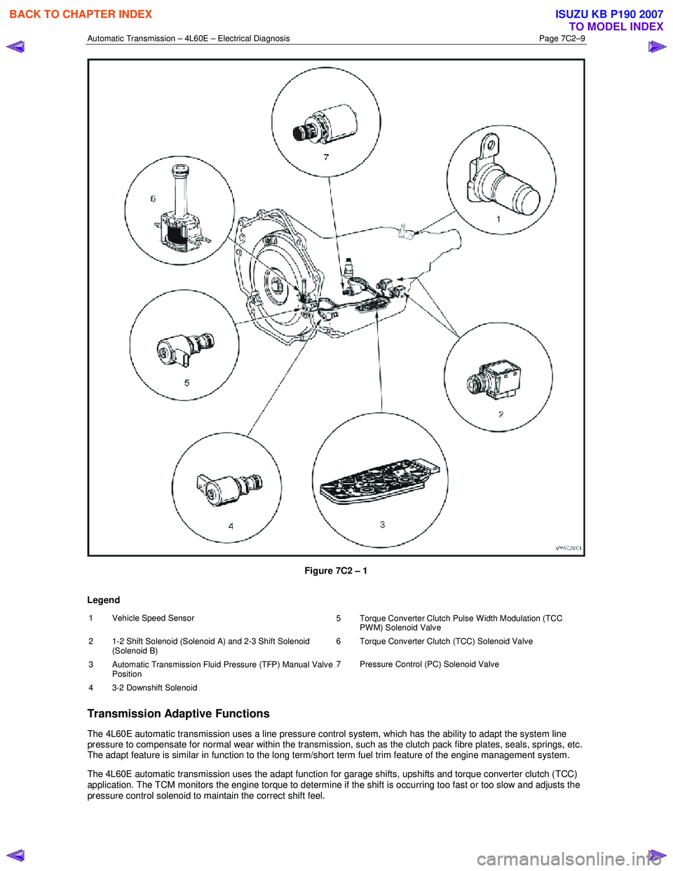
Figure 7C2 – 1 shows the location of the internal electronic components in the transmission.
BACK TO CHAPTER INDEX
TO MODEL INDEX
ISUZU KB P190 2007
Page 3795 of 6020
Automatic Transmission – 4L60E – Electrical Diagnosis Page 7C2–9
Figure 7C2 – 1
Legend
1 Vehicle Speed Sensor 5 Torque Converter Clutch Pulse Width Modulation (TCC
PWM) Solenoid Valve
2 1-2 Shift Solenoid (Solenoid A) and 2-3 Shift Solenoid (Solenoid B) 6 Torque Converter Clutch (TCC) Solenoid Valve
3
Automatic Transmission Fluid Pressure (TFP) Manual Valve
Position 7 Pressure Control (PC) Solenoid Valve
4 3-2 Downshift Solenoid
Transmission Adaptive Functions
The 4L60E automatic transmission uses a line pressure control system, which has the ability to adapt the system line
pressure to compensate for normal wear within the transmission, such as the clutch pack fibre plates, seals, springs, etc.
The adapt feature is similar in function to the long term/short term fuel trim feature of the engine management system.
The 4L60E automatic transmission uses the adapt function for garage shifts, upshifts and torque converter clutch (TCC)
application. The TCM monitors the engine torque to determine if the shift is occurring too fast or too slow and adjusts the
pressure control solenoid to maintain the correct shift feel.
BACK TO CHAPTER INDEX
TO MODEL INDEX
ISUZU KB P190 2007
Page 3797 of 6020

Automatic Transmission – 4L60E – Electrical Diagnosis Page 7C2–11
Figure 7C2 – 2
The TCM is an electronic control module receiving input or providing output to control the operation of the 4L60E
automatic transmission.
The TCM receives the following inputs from the engine control module (ECM):
• engine speed and torque values,
• engine intake air temperature (IAT), accelerator pedal position (APP) information,
• engine coolant temperature (ECT),
• driver selected shift mode, and
• air-conditioning (A/C) status.
The ECM provides this data to the TCM through the databus.
Other TCM inputs are:
• battery and ignition voltage,
• brake switch status,
• transmission fluid temperature (TFT), and
vehicle speed sensor (VSS).
The TCM provides the following outputs to control the automatic transmission:
• shift solenoids to control transmission shifting,
• torque converter clutch (TCC) pulse width modulated (PW M) solenoid operation to control the apply and release of
the torque converter clutch assembly, and
• pressure control (PC) solenoid to regulate the transmission line pressure.
Other TCM outputs provided to the ECM / PIM are:
• MIL illumination request,
• vehicle speed,
BACK TO CHAPTER INDEX
TO MODEL INDEX
ISUZU KB P190 2007
Page 3798 of 6020

Automatic Transmission – 4L60E – Electrical Diagnosis Page 7C2–12
• transmission fluid temperature,
• commanded gear status,
• TCC status, and
• torque reduction requests.
BACK TO CHAPTER INDEX
TO MODEL INDEX
ISUZU KB P190 2007
Page 3802 of 6020

Automatic Transmission – 4L60E – Electrical Diagnosis Page 7C2–16
Programming
If Programming is selected, a selection list is displayed which contains:
• Reset TAP Cells – This test allows the user to reset the Transmission Adapt (TAP) cells by pressing the Reset soft
key.
NOTE
Upon resetting the TAP cells the TCM loses all
learnt adaptive functions. When the vehicle is first
driven after this, the shifts may be harsh. This
harshness will ease as the TCM relearns the TAP
cells.
3.2 Data Display
If Data Display is selected, a selection list is displayed which contains the following:
Transmission Data
Once this mode, a list of transmission components and the TCM inputs are displayed along with their status.
Transmission Data Parameters
For definitions of the parameters in this table, refer to 3.3 Tech 2 Data Definitions.
Tech 2 Parameter Units Displayed Typical Data Value
Engine Torque Nm Varies
Throttle Position Percent Varies
Engine Speed RPM Varies
AT Input Speed N/A N/A
AT Output Speed RPM Varies
Vehicle Speed km/h 0
Commanded Gear 1,2,3,4 1
Shift Solenoid A On / Off Varies
Shift Solenoid B On / Off Varies
3-2 Downshift Solenoid On/Off On
Estimated Gear Ratio Ratio 8.00:1
Speed Ratio Ratio 8.00:1
Torque Converter Efficiency Ratio .00:1
TFP Switch A Open 12 V / Closed 0 V Varies
TFP Switch B Open 12 V / Closed 0 V Varies
TFP Switch C Open 12 V / Closed 0 V Varies
Engine Coolant Temperature °C Varies
Transmission Fluid Temp °C Varies
Transmission Hot Mode On/Off Off
PCS Actual Current Amps Varies (0.1 – 1.1 A)
PCS Desired Current Amps Varies (0.1 – 1.1 A)
PCS Duty Cycle Percent Varies
BACK TO CHAPTER INDEX
TO MODEL INDEX
ISUZU KB P190 2007
Page 3804 of 6020
Automatic Transmission – 4L60E – Electrical Diagnosis Page 7C2–18
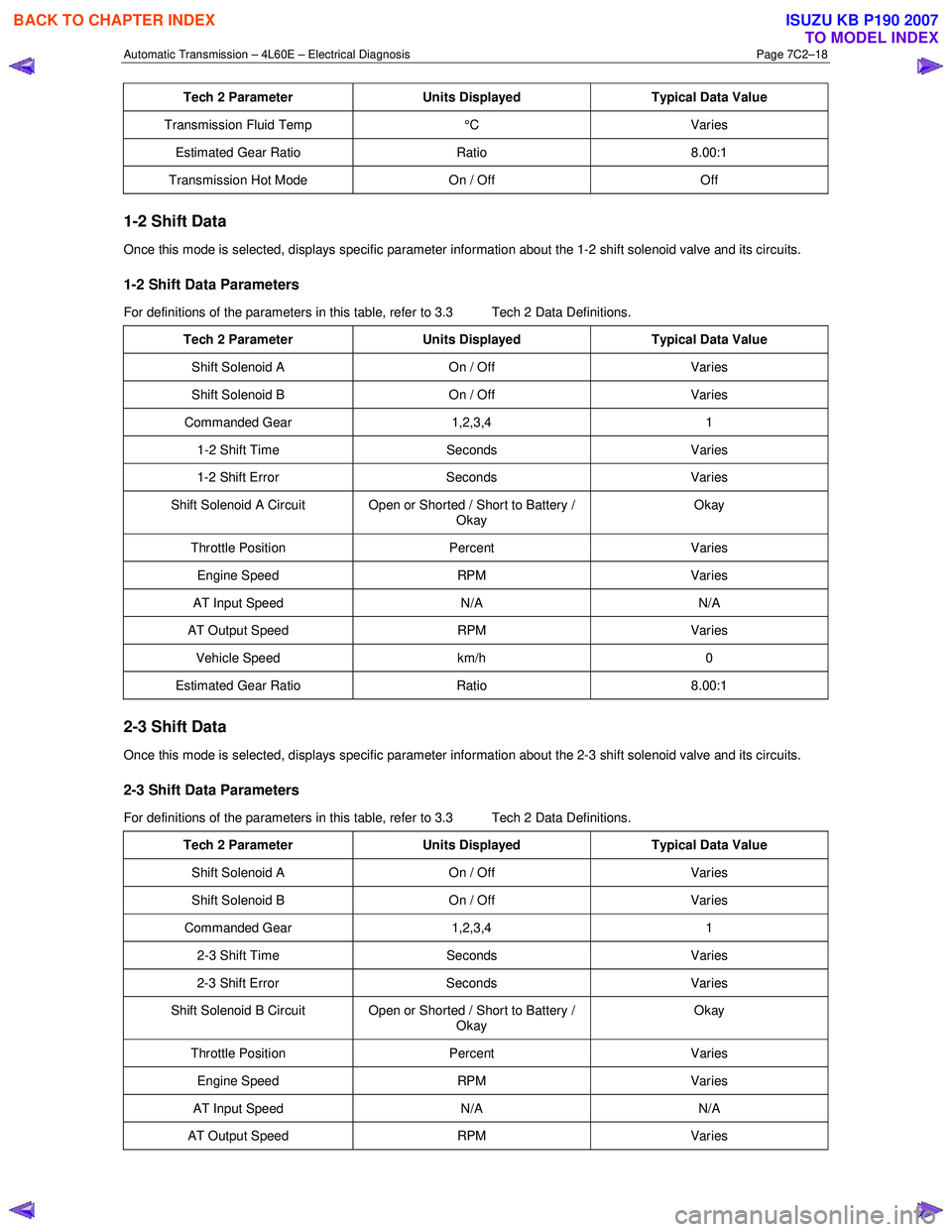
Tech 2 Parameter Units Displayed Typical Data Value
Transmission Fluid Temp °C Varies
Estimated Gear Ratio Ratio 8.00:1
Transmission Hot Mode On / Off Off
1-2 Shift Data
Once this mode is selected, displays specific parameter information about the 1-2 shift solenoid valve and its circuits.
1-2 Shift Data Parameters
For definitions of the parameters in this table, refer to 3.3 Tech 2 Data Definitions.
Tech 2 Parameter Units Displayed Typical Data Value
Shift Solenoid A On / Off Varies
Shift Solenoid B On / Off Varies
Commanded Gear 1,2,3,4 1
1-2 Shift Time Seconds Varies
1-2 Shift Error Seconds Varies
Shift Solenoid A Circuit Open or Shorted / Short to Battery /
Okay Okay
Throttle Position
Percent Varies
Engine Speed RPM Varies
AT Input Speed N/A N/A
AT Output Speed RPM Varies
Vehicle Speed km/h 0
Estimated Gear Ratio Ratio 8.00:1
2-3 Shift Data
Once this mode is selected, displays specific parameter information about the 2-3 shift solenoid valve and its circuits.
2-3 Shift Data Parameters
For definitions of the parameters in this table, refer to 3.3 Tech 2 Data Definitions.
Tech 2 Parameter Units Displayed Typical Data Value
Shift Solenoid A On / Off Varies
Shift Solenoid B On / Off Varies
Commanded Gear 1,2,3,4 1
2-3 Shift Time Seconds Varies
2-3 Shift Error Seconds Varies
Shift Solenoid B Circuit Open or Shorted / Short to Battery /
Okay Okay
Throttle Position
Percent Varies
Engine Speed RPM Varies
AT Input Speed N/A N/A
AT Output Speed RPM Varies
BACK TO CHAPTER INDEX
TO MODEL INDEX
ISUZU KB P190 2007
Page 3806 of 6020
Automatic Transmission – 4L60E – Electrical Diagnosis Page 7C2–20
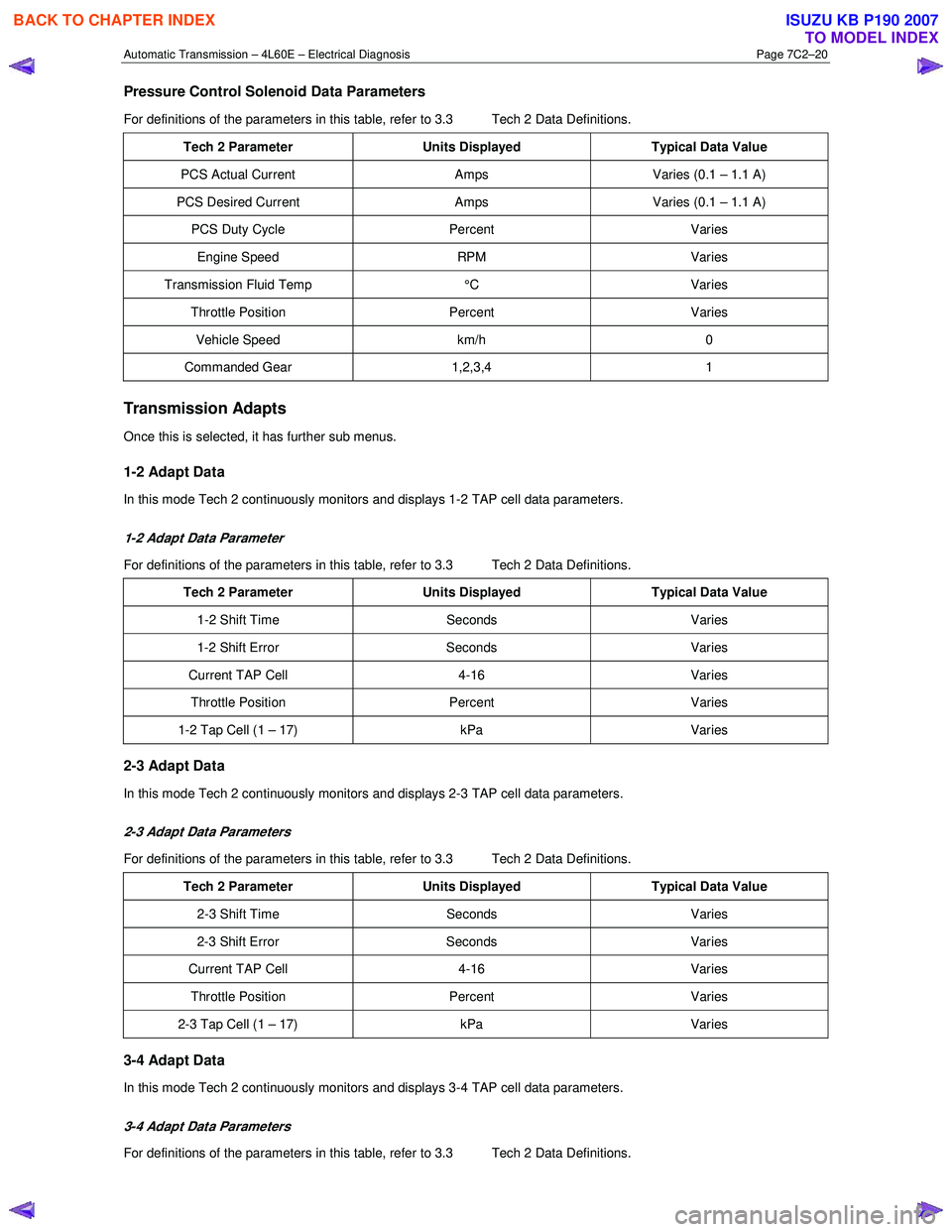
Pressure Control Solenoid Data Parameters
For definitions of the parameters in this table, refer to 3.3 Tech 2 Data Definitions.
Tech 2 Parameter Units Displayed Typical Data Value
PCS Actual Current Amps Varies (0.1 – 1.1 A)
PCS Desired Current Amps Varies (0.1 – 1.1 A)
PCS Duty Cycle Percent Varies
Engine Speed RPM Varies
Transmission Fluid Temp °C Varies
Throttle Position Percent Varies
Vehicle Speed km/h 0
Commanded Gear 1,2,3,4 1
Transmission Adapts
Once this is selected, it has further sub menus.
1-2 Adapt Data
In this mode Tech 2 continuously monitors and displays 1-2 TAP cell data parameters.
1-2 Adapt Data Parameter
For definitions of the parameters in this table, refer to 3.3 Tech 2 Data Definitions.
Tech 2 Parameter Units Displayed Typical Data Value
1-2 Shift Time Seconds Varies
1-2 Shift Error Seconds Varies
Current TAP Cell 4-16 Varies
Throttle Position Percent Varies
1-2 Tap Cell (1 – 17) kPa Varies
2-3 Adapt Data
In this mode Tech 2 continuously monitors and displays 2-3 TAP cell data parameters.
2-3 Adapt Data Parameters
For definitions of the parameters in this table, refer to 3.3 Tech 2 Data Definitions.
Tech 2 Parameter Units Displayed Typical Data Value
2-3 Shift Time Seconds Varies
2-3 Shift Error Seconds Varies
Current TAP Cell 4-16 Varies
Throttle Position Percent Varies
2-3 Tap Cell (1 – 17) kPa Varies
3-4 Adapt Data
In this mode Tech 2 continuously monitors and displays 3-4 TAP cell data parameters.
3-4 Adapt Data Parameters
For definitions of the parameters in this table, refer to 3.3 Tech 2 Data Definitions.
BACK TO CHAPTER INDEX
TO MODEL INDEX
ISUZU KB P190 2007
Page 3809 of 6020
Automatic Transmission – 4L60E – Electrical Diagnosis Page 7C2–23
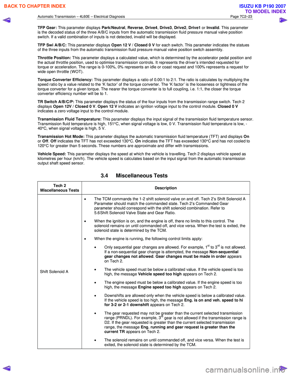
TFP Gear: This parameter displays Park/Neutral, Reverse , Drive4 , Drive3 , Drive2 , Drive1 or Invalid . This parameter
is the decoded status of the three A/B/C inputs from the automatic transmission fluid pressure manual valve position
switch. If a valid combination of inputs is not detected, invalid will be displayed.
TFP Swi A/B/C: This parameter displays Open 12 V / Closed 0 V for each switch. This parameter indicates the statues
of the three inputs from the automatic transmission fluid pressure manual valve position switch assembly.
Throttle Position: This parameter displays a calculated value, which is determined by the accelerator pedal position and
the actual throttle position, used to optimise transmission controls. It represents the driver’s intended requested for
torque or acceleration. The range is 0-100%, 0% represents an idle or coast request and 100% represents a request for
wide open throttle (WOT).
Torque Converter Efficiency: This parameter displays a ratio of 0.00:1 to 2:1. The ratio is calculates by multiplying the
speed ratio by a value related to the ‘K factor’ of the torque converter. The ‘K factor’ is the looseness or tightness of the
torque converter for a given torque. The nearer the torque converter is to full coupling, i.e. 1:1, the closer the torque
converter efficiency number will be to 1.
TR Switch A/B/C/P: This parameter displays the status of the four inputs from the transmission range switch. Tech 2
displays Open 12V / Closed 0 V . Open 12 V indicates an ignition voltage input to the control module. Closed 0 V
indicates a zero voltage input to the control module.
Transmission Fluid Temperature: This parameter displays the input signal of the transmission fluid temperature sensor.
Transmission fluid temperature is high, 151°C, when signal voltage is low, 0 V. Transmission fluid temperature is low, -
40°C, when signal voltage is high, 5 V.
Transmission Hot Mode: This parameter displays the automatic transmission fluid temperature (TFT) and displays On
or Off . Off indicates the TFT has not exceeded 130°C. On indicates the TFT has exceeded 130°C and has not cooled to
120°C for greater than 5 seconds. These numbers are approximate and differ with transmissions.
Vehicle Speed: This parameter displays the speed at which the vehicle is travelling. Tech 2 displays vehicle speed as
kilometres per hour (km/h). The vehicle speed is calculates based on the input signal from the automatic transmission
output shaft speed sensor.
3.4 Miscellaneous Tests
Tech 2
Miscellaneous Tests Description
Shift Solenoid A •
The TCM commands the 1-2 shift solenoid valve on and off. Tech 2’s Shift Solenoid A
Parameter should match the commanded state. Tech 2’s Commanded Gear
parameter should correspond with the shift solenoid combination. Refer to
5.6 Shift Solenoid Valve State and Gear Ratio.
• When the ignition is on, and the engine is off, there no limits to this control. The
solenoid remains on until commanded off, and vice versa. W hen the test is exited, the
solenoid state is determined by the TCM.
• W hen the engine is running, the following control limits apply:
• Only sequential gear changes are allowed. For example, 1
st to 3rd is not allowed.
If a non-sequential gear change is attempted, the message Non-sequential
gear changes not allowed . Gear changes must be made in order appears
on Tech 2.
• The vehicle speed must be below a calibrated value. If the vehicle speed is too
high, the message Vehicle speed too high appears on Tech 2.
• The engine speed must be below a calibrated value. If the engine speed is too
high, the message Engine speed too high appears on Tech 2.
• Downshifts are allowed only when the vehicle speed is below a calibrated value.
If the vehicle speed is too high, the message Eng. is on and veh. speed to hi
for 3-2 or 2-1 downshift appears on Tech 2.
• The gear requested may not be greater than the current selected transmission
range (PRNDL). For example, 3
rd gear is not allowed if the transmission range is
D2. If the gear requested is greater than the current selected transmission
range, the message Eng. running and gear request is greater than the
current TR appears on Tech 2.
• The solenoid remains on until commanded off, and vice versa. W hen the test is
exited, the solenoid state is determined by the TCM.
BACK TO CHAPTER INDEX
TO MODEL INDEX
ISUZU KB P190 2007
Page 3817 of 6020
Automatic Transmission – 4L60E – Electrical Diagnosis Page 7C2–31
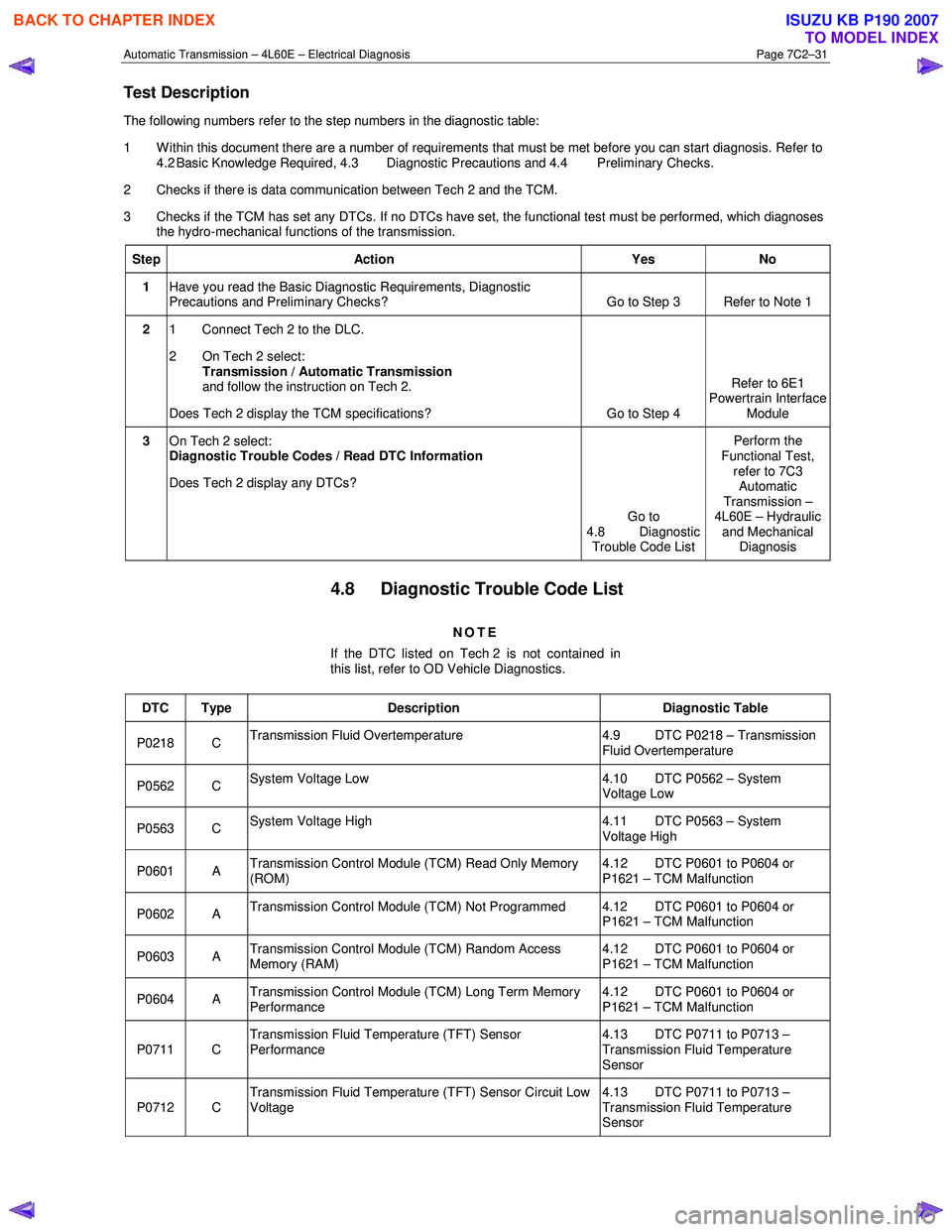
Test Description
The following numbers refer to the step numbers in the diagnostic table:
1 Within this document there are a number of requirements that must be met before you can start diagnosis. Refer to 4.2 Basic Knowledge Required, 4.3 Diagnostic Precautions and 4.4 Preliminary Checks.
2 Checks if there is data communication between Tech 2 and the TCM.
3 Checks if the TCM has set any DTCs. If no DTCs have set, the functional test must be performed, which diagnoses the hydro-mechanical functions of the transmission.
Step Action Yes No
1 Have you read the Basic Diagnostic Requirements, Diagnostic
Precautions and Preliminary Checks? Go to Step 3 Refer to Note 1
2
1 Connect Tech 2 to the DLC.
2 On Tech 2 select: Transmission / Automatic Transmission
and follow the instruction on Tech 2.
Does Tech 2 display the TCM specifications? Go to Step 4 Refer to 6E1
Powertrain Interface
Module
3 On Tech 2 select:
Diagnostic Trouble Codes / Read DTC Information
Does Tech 2 display any DTCs?
Go to
4.8 Diagnostic Trouble Code List Perform the
Functional Test, refer to 7C3 Automatic
Transmission –
4L60E – Hydraulic and Mechanical Diagnosis
4.8 Diagnostic Trouble Code List
NOTE
If the DTC listed on Tech 2 is not contained in
this list, refer to OD Vehicle Diagnostics.
DTC Type Description Diagnostic Table
P0218 C Transmission Fluid Overtemperature 4.9 DTC P0218 – Transmission
Fluid Overtemperature
P0562 C System Voltage Low 4.10 DTC P0562 – System
Voltage Low
P0563 C System Voltage High 4.11 DTC P0563 – System
Voltage High
P0601 A Transmission Control Module (TCM) Read Only Memory
(ROM) 4.12 DTC P0601 to P0604 or
P1621 – TCM Malfunction
P0602 A Transmission Control Module (TCM) Not Programmed 4.12 DTC P0601 to P0604 or
P1621 – TCM Malfunction
P0603 A Transmission Control Module (TCM) Random Access
Memory (RAM) 4.12 DTC P0601 to P0604 or
P1621 – TCM Malfunction
P0604 A Transmission Control Module (TCM) Long Term Memory
Performance 4.12 DTC P0601 to P0604 or
P1621 – TCM Malfunction
P0711 C Transmission Fluid Temperature (TFT) Sensor
Performance 4.13 DTC P0711 to P0713 –
Transmission Fluid Temperature
Sensor
P0712 C Transmission Fluid Temperature (TFT) Sensor Circuit Low
Voltage 4.13 DTC P0711 to P0713 –
Transmission Fluid Temperature
Sensor
BACK TO CHAPTER INDEX
TO MODEL INDEX
ISUZU KB P190 2007