automatic transmission fluid ISUZU KB P190 2007 Workshop User Guide
[x] Cancel search | Manufacturer: ISUZU, Model Year: 2007, Model line: KB P190, Model: ISUZU KB P190 2007Pages: 6020, PDF Size: 70.23 MB
Page 3198 of 6020
Engine Cooling – V6 Engine Page 6B1–63
4.5 Problems Not Requiring Disassembly of
Cooling System
1 Large obstructions blocking radiator or condenser airflow.
• Auxiliary oil coolers
• License plate
• Obstruction of radiator grille, for example, driving lights or mud
2 Loose, damaged or missing air chute side panels.
3 Missing or damaged air baffle.
4 Cracked or loose coolant recovery system hose.
5 Leaking heater component such as the heater core or water valve.
4.6 Problems Requiring Disassembly of Cooling System
1 Damaged cooling fan or faulty motor operation.
2 Pressure test cooling system.
3 Defective coolant pump.
• Eroded or broken impeller vanes
• Failed bearing or seal – check for shaft or bearing end play
4 Internally blocked radiator core.
5 Obstruction of coolant recovery system.
6 Internal system leaks.
• Head gaskets
• Cracked cylinder block
• Engine front cover
• Intake manifold gaskets
7 Blocked coolant passages in cylinder heads or block – remove cylinder heads and check.
4.7 Black Light and Dye Leak Diagnosis Method
It is strongly recommended that this diagnostic method be used to diagnose fluid leaks. This method is a proven and
reliable method that identifies the specific leak source.
The black light kit can be used for the leak detection of a number of fluids, when used with the appropriate tracer dye.
Examples are: Coolant, Engine Oil, Automatic Transmission Fluid and Air Conditioning Refrigerant (R134A).
The following is a summary of the steps involved in detecting a cooling system fluid leak using black light and dye:
1 Pour specified amount of dye into the cooling system via the coolant filler cap on the outlet housing. Refer 3.1 Service Notes in this Section.
2 Road test the vehicle under normal operating conditions.
3 Direct the light towards the suspect area. The fluid leak will appear as a brightly coloured path leading from the source.
4 Repair fluid leak and recheck to ensure that leak has been rectified.
5 Refer to the manufacturer’s directions when using this method.
BACK TO CHAPTER INDEX
TO MODEL INDEX
ISUZU KB P190 2007
Page 3202 of 6020
Engine Cooling – V6 Engine Page 6B1–67
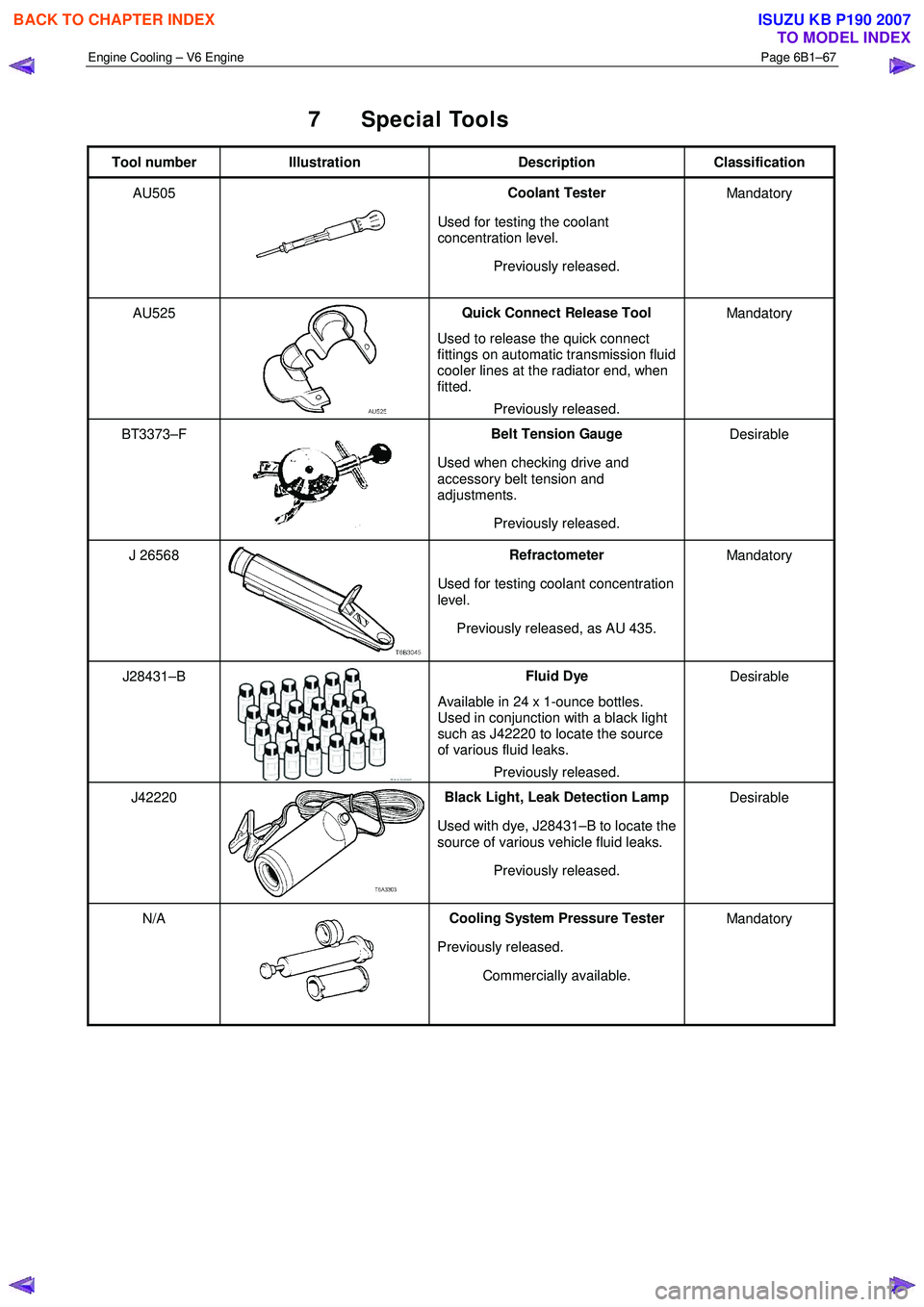
7 Special Tools
Tool number Illustration Description Classification
AU505
Coolant Tester
Used for testing the coolant
concentration level.
Previously released. Mandatory
AU525
Quick Connect Release Tool
Used to release the quick connect
fittings on automatic transmission fluid
cooler lines at the radiator end, when
fitted.
Previously released. Mandatory
BT3373–F
Belt Tension Gauge
Used when checking drive and
accessory belt tension and
adjustments.
Previously released. Desirable
J 26568 Refractometer
Used for testing coolant concentration
level.
Previously released, as AU 435. Mandatory
J28431–B Fluid Dye
Available in 24 x 1-ounce bottles.
Used in conjunction with a black light
such as J42220 to locate the source
of various fluid leaks.
Previously released. Desirable
J42220 Black Light, Leak Detection Lamp
Used with dye, J28431–B to locate the
source of various vehicle fluid leaks.
Previously released. Desirable
N/A Cooling System Pressure Tester
Previously released. Commercially available. Mandatory
BACK TO CHAPTER INDEX
TO MODEL INDEX
ISUZU KB P190 2007
Page 3324 of 6020
Engine Management – V6 – Diagnostics Page 6C1-2–46
6.5 Alcohol / Contaminants in Fuel
Diagnosis
Description
W ater contamination in the fuel system may cause driveability conditions such as hesitation, stalling, no start, or
misfires in one or more cylinders. W ater may collect near a single fuel injector at the lowest point in the fuel rail, and
cause a misfire in that cylinder. If the fuel system is contaminated with water, inspect the fuel system components for
rust, or deterioration.
Alcohol (e.g. Ethanol) concentrations more than 10% in the fuel can be detrimental to fuel system components. Alcohol
contamination may cause fuel system corrosion, deterioration of rubber components, and subsequent fuel filter
restriction. Fuel contaminated with alcohol may cause driveability conditions such as hesitation, lack of power, stalling,
or no start. Some types of alcohol are more detrimental to fuel system components than others.
Alcohol in Fuel Testing Procedure
NOTE
The procedures detailed are not intended to be
accurate but rather, indicative of a contamination
situation.
The fuel sample should be drawn from the bottom of the tank so that any water present in the tank will be detected. The
sample should be bright and clear. If alcohol contamination is suspected, then use the following procedure to test the
fuel quality.
• Using a 100 ml graduated cylinder with 1 ml marks, fill the cylinder with fuel to the 90 ml mark.
• Add 10 ml of water to bring the total fluid volume to 100 ml and install a stopper.
• Shake the cylinder vigorously for 10 – 15 seconds.
• Carefully loosen the stopper to release the pressure.
• Re-install the stopper and shake the cylinder vigorously again for 10 – 15 seconds.
• Put the cylinder on a level surface for approximately 5 minutes to allow adequate liquid separation.
If alcohol is present in the fuel, the volume of the lower layer, that now contains both alcohol and water, will be more
than 10 ml. For example, if the volume of the lower layer is increased to 15 ml, this indicates at least 5 percent alcohol in
the fuel. The actual amount of alcohol may be somewhat more because this procedure does not extract all of the
alcohol from the fuel. To obtain an accurate determination of the amount of alcohol contamination in a given fuel sample,
then professional analysis should be sought.
Particulate Contaminants in Fuel Testing Procedure
The fuel sample should be drawn from the bottom of the tank so that any contaminants present in the tank will be
detected. The sample should be bright and clear. If the sample appears cloudy or contaminated with water as indicated
by a water layer at the bottom of the sample, use the following procedure to diagnose the fuel.
• Using an approved fuel container, draw approximately 0.5 litre of fuel.
• Place the cylinder on a level surface for approximately 5 minutes to allow settling of the particulate contamination.
Particulate contamination will show up in various shapes and colours. Sand will typically be identified by a white or light
brown crystals. Rubber will appear as black and irregular particles. If particles are found, clean the entire fuel system
thoroughly. Refer to 6C Fuel System – V6.
6.6 Crankshaft Position (CKP) System
Variation Learn Procedure
Description
The crankshaft position system variation learn feature is carried out automatically on the HFV6 engine under decel with
fuel cut. The road speed and duration of the self-learn process varies with different vehicle equipment levels such as
transmission, final drive ratio etc.
The variation learn procedure cannot be over-written, nor can it be accessed with Tech 2.
BACK TO CHAPTER INDEX
TO MODEL INDEX
ISUZU KB P190 2007
Page 3531 of 6020
Engine Management – V6 – Service Operations Page 6C1-3–7
Transmission – Automatic
For automatic transmission sensors and components, refer to 7C4 Automatic Transmission – 4L60E – On-vehicle
Servicing.
Transmission – Manual
For manual transmission sensors and other components, refer to 7B1 Manual Transmission – V6.
1.4 Warning Caution and Notes
This Section contains various W ARNINGS, CAUTIONS and NOTE statements that you must observe carefully to reduce
the risk of death or injury during service, repair procedures or vehicle operation. Incorrect service or repair procedures
may damage the vehicle or cause operational faults. W ARNINGS, CAUTION and NOTE statements are not exhaustive.
GM Holden LTD can not possibly warn of all the potentially hazardous consequences of failure to follow these
instructions.
Definition of WARNING, CAUTION and NOTE Statements
Diagnosis and repair procedures in this Section contain both general and specific W ARNING, CAUTION and NOTE
statements. GM Holden LTD is dedicated to the presentation of service information that helps the technician to diagnose
and repair the systems necessary for proper operation of the vehicle. Certain procedures may present a hazard to the
technician if they are not followed in the recommended manner. W ARNING, CAUTION and NOTE statements are
designed to help prevent these hazards from occurring, but not all hazards can be foreseen.
WARNING defined
A W ARNING statement immediately precedes an operating procedure or maintenance practice which, if not correctly
followed, could result in death or injury. A W ARNING statement alerts you to take necessary action or not to take a
prohibited action. If a W ARNING statement is ignored, the following consequences may occur:
• Death or injury to the technician or other personnel working on the vehicle,
• Death or injury to other people in or near the workplace area, and / or
• Death or injury to the driver / or passenger(s) of the vehicle or other people, if the vehicle has been improperly
repaired.
CAUTION defined
A CAUTION statement immediately precedes an operating procedure or maintenance practice which, if not correctly
followed, could result in damage to or destruction of equipment, or corruption of data. If a CAUTION statement is ignored,
the following consequences may occur:
• Damage to the vehicle,
• Unnecessary vehicle repairs or component replacement,
• Faulty operation or performance of any system or component being repaired,
• Damage to any system or components which depend on the proper operation of the system or component being
repaired,
• Faulty operation or performance of any systems or components which depend on the proper operation or
performance of the system or component under repair,
• Damage to fasteners, basic tools or special tools and / or
• Leakage of coolant, lubricant or other vital fluids.
NOTE defined
A NOTE statement immediately precedes or follows an operating procedure, maintenance practice or condition that
requires highlighting. A NOTE statement also emphasises necessary characteristics of a diagnostic or repair procedure.
A NOTE statement is designed to:
• Clarify a procedure,
• Present additional information for accomplishing a procedure,
BACK TO CHAPTER INDEX
TO MODEL INDEX
ISUZU KB P190 2007
Page 3763 of 6020

Automatic Transmission – 4L60E – General Information Page 7C1–3
1 Section Descriptions
Service information for the Hydra-matic 4L60E Automatic transmission has been divided into five Sections to assist the
technician to quickly locate the correct service, maintenance and diagnostic information.
The following provides a brief outline of each of the Sections.
• 7C1 Automatic Transmission – 4L60E – General Information
• 7C2 Automatic Transmission – 4L60E – Electrical Diagnosis
• 7C3 Automatic Transmission – 4L60E – Hydraulic and Mechanical Diagnosis
• 7C4 Automatic Transmission – 4L60E – On-vehicle Servicing
The following provides a brief outline of each of the Sections.
1.1 WARNINGS, CAUTIONS and NOTES
This Section contains various W ARNINGS, CAUTIONS and NOTE statements that you must observe carefully to reduce
the risk of death or injury during service, repair procedures or vehicle operation. Incorrect service or repair procedures
may damage the vehicle or cause operational faults. W ARNINGS, CAUTION and NOTE statements are not exhaustive.
GM HOLDEN LTD can not possibly warn of all the potentially hazardous consequences of failure to follow these
instructions.
Definition of WARNING, CAUTION and NOTE Statements
Diagnosis and repair procedures in this Section contain both general and specific W ARNING, CAUTION and NOTE
statements. GM HOLDEN LTD is dedicated to the presentation of service information that helps the technician to
diagnose and repair the systems necessary for proper operation of the vehicle. Certain procedures may present a hazard
to the technician if they are not followed in the recommended manner. W ARNING, CAUTION and NOTE statements are
designed to help prevent these hazards from occurring, but not all hazards can be foreseen.
WARNING Defined
A W ARNING statement immediately precedes an operating procedure or maintenance practice which, if not correctly
followed, could result in death or injury. A WARNING statement alerts you to take necessary action or not to take a
prohibited action. If a W ARNING statement is ignored, the following consequences may occur:
• Death or injury to the technician or other personnel working on the vehicle,
• Death or injury to other people in or near the workplace area, and / or
• Death or injury to the driver / or passenger(s) of the vehicle or other people, if the vehicle has been improperly
repaired.
CAUTION Defined
A CAUTION statement immediately precedes an operating procedure or maintenance practice which, if not correctly
followed, could result in damage to or destruction of equipment, or corruption of data. If a CAUTION statement is ignored,
the following consequences may occur:
• Damage to the vehicle,
• Unnecessary vehicle repairs or component replacement,
• Faulty operation or performance of any system or component being repaired,
• Damage to any system or components which depend on the proper operation of the system or component being
repaired,
• Faulty operation or performance of any systems or components which depend on the proper operation or
performance of the system or component under repair,
• Damage to fasteners, basic tools or special tools and / or
• Leakage of coolant, lubricant or other vital fluids.
NOTE Defined
A NOTE statement immediately precedes or follows an operating procedure, maintenance practice or condition that
requires highlighting. A NOTE statement also emphasises necessary characteristics of a diagnostic or repair procedure.
A NOTE statement is designed to:
• Clarify a procedure,
• Present additional information for accomplishing a procedure,
• Give insight into the reasons for performing a procedure in the recommended manner, and / or
• Present information that gives the technician the benefit of past experience in accomplishing a procedure with
greater ease.
BACK TO CHAPTER INDEX
TO MODEL INDEX
ISUZU KB P190 2007
Page 3764 of 6020
Automatic Transmission – 4L60E – General Information Page 7C1–4
1.2 7C1 Automatic Transmission – 4L60E –
General Information
This section provides general information about the automatic transmission, including:
• A glossary of terms,
• Transmission identification information,
• Electrical overview of the Transmission Control Module (TCM),
• Some notes that address safe workshop practices,
• Service notes relating to fasteners and consumable items used at various stages throughout this section,
• Special tools required to work on the transmission,
• Fastener torque specifications, and
• Transmission specifications.
For all information relating to the mechanical construction and function of the 4L60E automatic transmission, refer to the
General Motors Powertrain Group Electronically Controlled Automatic Transmission Technician’s Guide.
This guide includes such information as:
• Transmission Cutaway Views,
• Principles of Operation,
• Power Flow,
• Complete Hydraulic Circuits,
• Bushing and Bearing Locations,
• Seal Locations and
• Illustrated Parts List.
NOTE
Specifications quoted in this General Motors
Powertrain Group Electronically Controlled
Automatic Transmission Technician Guide may
not be for the vehicle you are working on. For
correct specifications refer to
7 Transmission Specifications.
Recommendations
When servicing the transmission, all parts should be cleaned and inspected. Individual units should be reassembled
before disassembly of other units to avoid confusion and interchanging of parts.
a Thoroughly clean the transmission exterior before removal of any component.
b Disassembly and reassembly must be made on a clean work bench. Cleanliness is of the utmost importance, the bench tools and parts must be kept clean at all times.
c Before installing screws and other fasteners into aluminium parts, dip screw threads into transmission fluid to prevent galling aluminium threads and to prevent screws from seizing.
d To prevent thread stripping, always use a torque wrench when installing screws or nuts.
e If threads in aluminium parts are stripped or damaged, the parts can be made serviceable by the use of commercially available thread inserts.
f Protective tools must be used when assembling seals to prevent damage. The slightest flaw in the sealing surface of the seal can cause an oil leak.
g Aluminium castings and valve parts are very susceptible to nicks, burrs, etc. and should be handled with care.
h Expand Internal snap rings and compress external snap rings if they are to be re-used to ensure proper seating when reinstalled.
i Do not re-use removed O-rings, gaskets and oil seals.
j Teflon oil seal rings should not be removed unless damaged.
k During assembly of each unit, all internal moving parts must be lubricated with transmission fluid.
Oil Cooler Pipes
Should any transmission fluid cooling pipe suffer accidental damage, a genuine replacement pipe must be fitted. Refer to
the current release of PartFinder™ to determine the correct part number for the particular engine and pipe involved.
Reworking of damaged pipes or hand made replacements are not permitted.
BACK TO CHAPTER INDEX
TO MODEL INDEX
ISUZU KB P190 2007
Page 3765 of 6020
Automatic Transmission – 4L60E – General Information Page 7C1–5
Clean and Inspect
Do not use solvents on neoprene seals,
composition faced clutch plates or thrust
washers as damage to parts may occur.
After complete disassembly of a component, wash all metal parts in a clean solvent and dry with compressed air. Blow
oil passages out and check to make sure they are not obstructed, small passages should be checked with tag wire. All
parts should be inspected to determine if replacement is required.
Pay particular attention to the following:
• Inspect linkage and pivot points for excessive wear.
• Bearing and thrust surfaces of all parts should be checked for excessive wear and scoring.
• Check for broken seal rings, damaged ring lands and damaged threads.
• Inspect seals for damage.
• Mating surfaces of castings should be checked for burrs. Irregularities may be removed by lapping the surface with
emery paper laid on a flat surface, such as a piece of plate glass.
• Castings should be checked for cracks and porosity.
1.3 7C2 Automatic Transmission – 4L60E –
Electrical Diagnosis
For transmissions fitted to V6 engines, the electrical diagnosis is in this Section. A new electrical circuit and control
module has been introduced for automatic transmissions fitted to the V6 engines.
1.4 7C3 Automatic Transmission – 4L60E – Hydraulic and Mechanical Diagnosis
Information contained in 7C3 Automatic Transmission – 4L60E – Hydraulic and Mechanical Diagnosis will assist in the
diagnosis of the mechanical and hydraulic components in the 4L60E automatic transmission, while the transmission
remains installed on the vehicle.
Examples of the type of diagnostic information contained within this section are:
• transmission functional test,
• line pressure information,
• transmission fluid diagnosis,
• symptom diagnosis and
• shift speed charts.
1.5 7C4 Automatic Transmission – 4L60E –
On-vehicle Servicing
Information in 7C4 Automatic Transmission – 4L60E – On-vehicle Servicing covers transmission fluid level checking, as
well as specific information for servicing some components while the transmission remains installed on the vehicle. This
Section also covers the transmission removal and reinstallation to the vehicle.
BACK TO CHAPTER INDEX
TO MODEL INDEX
ISUZU KB P190 2007
Page 3768 of 6020
Automatic Transmission – 4L60E – General Information Page 7C1–8
2.4 System Protection Devices
Should 1st gear be selected and left in that range, the TCM will protect the engine from an over-speeding condition by
upshifting to 2nd gear at a pre-determined point. Similarly, the TCM provides high speed, downshift protection by
preventing a manual shift into 1st gear above pre-determined engine speeds.
Under severe operating conditions such as towing in high ambient temperatures, fluid temperatures can rise to a point
where lubrication breakdown can occur. In addition to having an oil cooler fitted to the vehicle, the 4L60E transmission is
also fitted with a transmission fluid temperature sensor located in the Transmission Range (TR) Pressure Switch
Assembly (PSA).
When fluid temperatures in excess of 135 °C are sensed, the torque converter clutch is applied as programmed, in 3rd or
4th gear. This action reduces further the fluid temperature during normal operation of the torque converter. While these
high fluid temperatures are sensed however, torque converter clutch apply is not available when the throttle opening is
above 50%.
Similarly, when the fluid temperature is below 29 °C, the TCM prevents torque converter clutch apply.
If a condition occurs, preventing electronic control of the transmission's functions, a 'Fail Safe' mode will default the
transmission to 3rd gear when either Drive or 3 is selected, applying also maximum line pressure. W hile in this mode, the
vehicle operator can still manually select 2, 1, Reverse, Park or Neutral, should the need arise.
2.5 Self Diagnosis
If any transmission operation controlled by the TCM begins to operate outside its pre-set parameters, the TCM has the
ability to store a range of diagnostic codes which can be accessed by the servicing technician, thereby localising the
problem.
2.6 TCM Sensors and Actuators
As indicated earlier, there are a number of sensors and switches providing input information for the TCM programming
that will allow the TCM to change the shift pattern, shift feel and torque converter clutch operation.
The TCM does this by comparing this input information with its predetermined values on shift pattern, fluid pressure
maps, shift duration parameters, extreme heat protection programming and adaptive controls.
In addition, each input signal and output actuator operation is also monitored and if outside its pre-set parameters, a
diagnostic code is logged for future reference by the servicing technician.
BACK TO CHAPTER INDEX
TO MODEL INDEX
ISUZU KB P190 2007
Page 3769 of 6020
Automatic Transmission – 4L60E – General Information Page 7C1–9
3 Transmission Control Module
Operation Overview
3.1 Transmission Control Module
W ith the introduction of the new HFV6 engine, the powertrain architecture has been redesigned to accommodate this
introduction. W ith this design, a new bus architecture and protocol has also been introduced. The new bus connects the
following modules:
• engine control module (ECM),
• transmission control module (TCM),
• powertrain interface module (PIM) and
• ABS module.
The protocol used to communicate between these modules is called General Motors Local Area Network (GM LAN)
which is based on Controller Area Network (CAN) communication protocol. For further information on GM LAN protocol
and data bus structure, refer to 6E1 Powertrain Interface Module – V6.
Component Location
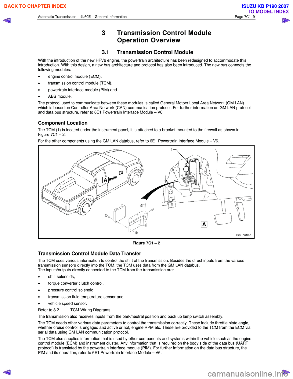
The TCM (1) is located under the instrument panel, it is attached to a bracket mounted to the firewall as shown in
Figure 7C1 – 2.
For the other components using the GM LAN databus, refer to 6E1 Powertrain Interface Module – V6.
Figure 7C1 – 2
Transmission Control Module Data Transfer
The TCM uses various information to control the shift of the transmission. Besides the direct inputs from the various
transmission sensors directly into the TCM, the TCM uses data from the GM LAN databus.
The inputs/outputs directly connected to the TCM from the transmission are:
• shift solenoids,
• torque converter clutch control,
• pressure control solenoid,
• transmission fluid temperature sensor and
• vehicle speed sensor.
Refer to 3.2 TCM Wiring Diagrams.
The transmission also receives inputs from the park/neutral position and back up lamp switch assembly.
The TCM needs other various data parameters to control the transmission correctly. These include throttle plate angle,
whether cruise control is engaged and active or not, engine RPM etc. These are provided to the TCM from the ECM via
serial data using GM LAN communication protocol.
The TCM also supplies information that is used by other components and systems within the vehicle such as the engine
control module (ECM) and instrument cluster. Any information that is required on the body side of the data bus (UART
protocol) is translated by the powertrain interface module (PIM). For further information on the data bus structure, the
PIM and its operation, refer to 6E1 Powertrain Interface Module – V6.
BACK TO CHAPTER INDEX
TO MODEL INDEX
ISUZU KB P190 2007
Page 3770 of 6020
Automatic Transmission – 4L60E – General Information Page 7C1–10
Transmission Control Module Operation
The TCM processes data every 10 milliseconds from various sensors, such as throttle position, vehicle speed, gear
range, temperature, engine load and other inputs. The TCM compares all its various inputs with the internal programming
and calibration of the TCM using this data, a signal is transmitted to the valve body shift solenoids, which activate the
shift valves for precise shift control. Shift points are therefore precisely controlled and are identical from vehicle to vehic le.
The TCM also control torque converter clutch apply and release.
Shift feel is also electronically controlled by the TCM, by signals sent to the variable force solenoid, which controls fluid
line pressure and it is this pressure that precisely determines how the shifts will feel. In this way, the TCM electronically
synchronises the engine and transmission into a single integrated powertrain system for optimum performance, shift
timing, fuel efficiency and emission control.
3.2 TCM Wiring Diagrams
For details of the transmission control module (TCM) wiring diagrams, refer to 8A Electrical-Body and Chassis.
BACK TO CHAPTER INDEX
TO MODEL INDEX
ISUZU KB P190 2007