fuse box ISUZU KB P190 2007 Workshop Workshop Manual
[x] Cancel search | Manufacturer: ISUZU, Model Year: 2007, Model line: KB P190, Model: ISUZU KB P190 2007Pages: 6020, PDF Size: 70.23 MB
Page 5170 of 6020

8A-232 ELECTRICAL-BODY AND CHASSIS
BACKUP LIGHT
1. Backup light does not light on one side (RH or LH)
Checkpoint Trouble Cause Countermeasure
Repair grounding point contactPoor ground contact
NGGrounding point
Replace the bulb or repair
connector contactBackup light bulb continuityBurned out bulb or poor
connector contact
NG
OK
2. Backup light does not light on both sides
Repair or replace the switch
Poor switch point contact of
faulty switch
NG
Voltage between 5 F6
(5
F5 ) - ground with
starter switch ON and shift
lev er into rev erse position
(Should be battery v oltage
present)
Back up light switch (mode
switch) continuity
Reinstall or replace fuse No.
C10 (15A)
Fuse No. C10 (15A, Fuse
box)
Poor fuse contact or blown
fuse
NG
OK
OK
Repair open circuit or
connector contact
Open circuit or poor connector
contact
NG
BACK TO CHAPTER INDEX
TO MODEL INDEXISUZU KB P190 2007
Page 5171 of 6020

ELECTRICAL-BODY AND CHASSIS 8A-233
HORN
1. Both sides of horn do not sound
Checkpoint Trouble Cause Countermeasure
Repair the grounding point
Poor ground contact
NG
Horn relay
Grounding point
Reinstall or replace fuse No.
EB15 (10A)
Fuse No EB15 (10A, Relay
and fuse box)
Poor fuse contact or blown
fuse
NG
OK
OK
Reinstall or replace the horn
relay
Poor relay contact or faulty
horn relay
NG
Voltage between connector
3
X3 - ground or 1 X3
- ground (Should be battery
v oltage present) OK
Repair open circuit or
reconnect the connector
Open circuit or poor connector
contact between fuse No.
EB15 (10A) and horn relay
NG
Remov e steering pad and
steering wheel
OK
Horn switch continuity
OK
Repair or replace the horn
switch
Poor switch point contact or
faulty switch
NG
Continuity between
5
X3 - 10 B60
2
X3 - 1 C20 (1 C21 )
OK
Repair open circuit or
connector contact
Open circuit or poor connector
contact
NG
BACK TO CHAPTER INDEX
TO MODEL INDEXISUZU KB P190 2007
Page 5346 of 6020

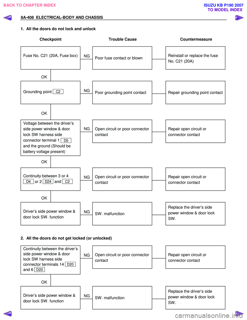
8A-408 ELECTRICAL-BODY AND CHASSIS
1. All the doors do not lock and unlock
Checkpoint Trouble Cause Countermeasure
Reinstall or replace the fuse
No. C21 (20A)
Poor fuse contact or blown
NG
Repair grounding point contact
Grounding point C2
Poor grounding point contact
Repair open circuit or
connector contact
Voltage between the driver’s
side power window & door
lock SW harness side
connector terminal 1
D5
and the ground (Should be
battery voltage present)
Open circuit or poor connector
contact
NG
NG
OK
OK
OK
Fuse No. C21 (20A, Fuse box)
Repair open circuit or
connector contact
Open circuit or poor connector
contact
NG
Replace the driver’s side
power window & door lock
SW .
Driver’s side power window &
door lock SW . function
SW . malfunction
NG
OK
Continuity between 3 or 4
D4 or 2 D24 and
C2
2. All the doors do not get locked (or unlocked)
Repair open circuit or
connector contact
Open circuit or poor connector
contact
NG
Replace the driver’s side
power window & door lock
SW .
Driver’s side power window &
door lock SW . function
SW . malfunction
NG
OK
Continuity between the driver’s
side power window & door
lock SW harness side
connector terminals 14
D20
and 6
D20
BACK TO CHAPTER INDEX TO MODEL INDEXISUZU KB P190 2007
Page 5366 of 6020

8A-428 ELECTRICAL-BODY AND CHASSIS
1. All windows do not operate
Checkpoint Trouble Cause Countermeasure
Reinstall or replace the fuse
C20 (30A)
Poor fuse contact or blown
NG
Replace the circuit breaker
C20 (50A or 60A)
C20 (50A or 60A Fuse box)
function
Circuit breaker malfunction
Repair grounding points
contact
Grounding points C2
Poor grounding point contact
NG
NG
OK
OK
OK
Fuse C20 (30A, Fuse box)
Replace the power window
relay
Power window relay
malfunction
NG
Repair an open circuit or a
poor connection of the
connectors between 1
C108
and 2
B8
Voltage between the power
window relay harness side
connector terminal 2
B8
and the ground (Should be
battery v oltage present)
Open circuit or poor connector
contact
NG
OK
Power window relay function
OK
Repair an open circuit or a
poor connection of the
connectors between 1
B8
and 1
B56 and 6 D5
Open circuit or poor connector
contact
NG Voltage between 6 D5 and
the ground (Should be battery
v oltage present)
OK
Repair an open circuit or a
poor connection of the
connectors between 3
D5
and
C2 , or 3 B8 (12
C107 ) and C109
Open circuit or poor connector
contact
NG
Continued on the next page
Voltage between 3
D5 or 3
B8 and the ground
BACK TO CHAPTER INDEX TO MODEL INDEXISUZU KB P190 2007
Page 5400 of 6020

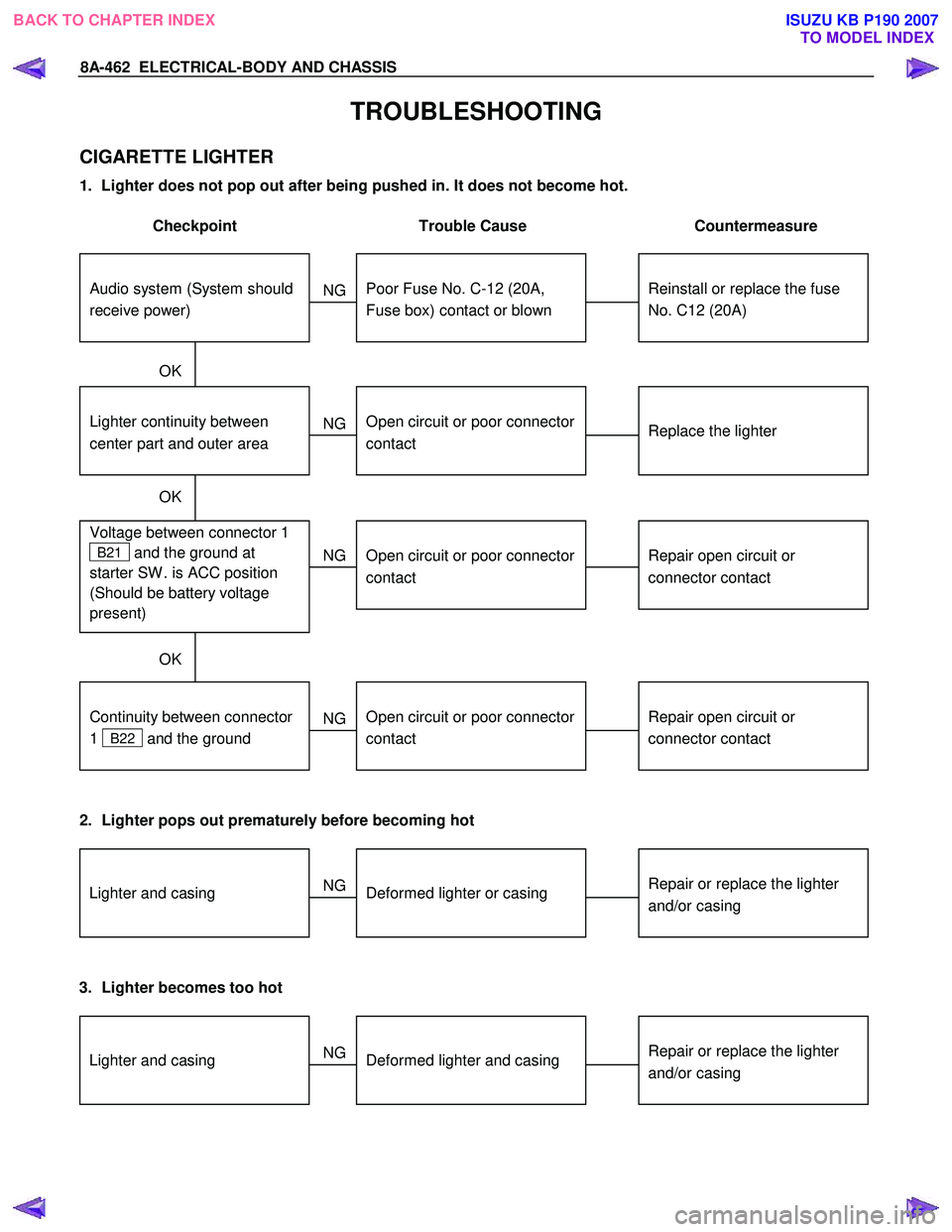
8A-462 ELECTRICAL-BODY AND CHASSIS
TROUBLESHOOTING
CIGARETTE LIGHTER
1. Lighter does not pop out after being pushed in. It does not become hot.
Checkpoint Trouble Cause Countermeasure
Reinstall or replace the fuse
No. C12 (20A)
Poor Fuse No. C-12 (20A,
Fuse box) contact or blown
NG
Replace the lighter
Lighter continuity between
center part and outer area
Open circuit or poor connector
contact
Repair open circuit or
connector contact
Voltage between connector 1
B21 and the ground at
starter SW . is ACC position
(Should be battery voltage
present)
Open circuit or poor connector
contact
NG
NG
OK
OK
OK
Audio system (System should
receive power)
Repair open circuit or
connector contact
Open circuit or poor connector
contact
NG
Continuity between connector
1
B22 and the ground
2. Lighter pops out prematurely before becoming hot
Repair or replace the lighter
and/or casingDeformed lighter or casing
NGLighter and casing
3. Lighter becomes too hot
Repair or replace the lighter
and/or casingDeformed lighter and casing
NGLighter and casing
BACK TO CHAPTER INDEX
TO MODEL INDEXISUZU KB P190 2007
Page 5411 of 6020

ELECTRICAL-BODY AND CHASSIS 8A-473
DOOR MIRROR CONTROL SWITCH
1. Mirrors on the both sides do not operate
Checkpoint Trouble Cause Countermeasure
Reinstall or replace the fuse
No. C11 (10A)
Poor fuse contact or blown
NG
Repair grounding point
C2
contact
Grounding point
C2
Poor grounding point contact
Repair an open circuit or a
poor connection of the
connectors between the fuse
No. C11 (10A) and 4
D19
Voltage between the door
mirror control SW . harness
side connector terminal
4
D19 and the ground
(Should be battery voltage
present)
Open circuit or poor connector
contact
NG
NG
OK
OK
OK
Fuse No. C11 (10A, Fuse box)
Repair open circuit or
connector contact
Open circuit or poor connector
contact
NG Continuity between the door
mirror control SW harness
side connector terminal
8
D19 and C2
Replace the door mirror
control SW .
Door mirror control SW .
function
SW . malfunction
NG
OK
Repair open circuit or
connector contact
Continuity between 7
D19
and 12
H36 (or 12 H37 )
Open circuit or poor connector
contact
NG
OK
BACK TO CHAPTER INDEX TO MODEL INDEXISUZU KB P190 2007
Page 5424 of 6020

8A-486 ELECTRICAL-BODY AND CHASSIS
TROUBLE SHOOTING
Rear defogger inoperative
Checkpoint Trouble Cause Countermeasure
Reinstall or replace the fuse
No. C7 (10A) and 9
B56
Poor fuse contact or blown
NG
Reinstall or replace the fuse
C18 (20A)
C18 (20A, Fuse box)
Poor fuse contact or blown
Replace the rear defogger
switch
Rear defogger switch function
Switch malfunction
NG
NG
OK
OK
OK
Fuse No. C3 (10A, Fuse box)
and 9
B56
Replace the rear defogger
relay
Relay malfunction
NG
Continued on the next page
Rear defogger relay function
Repair grounding point contact
Grounding point
C2
Poor grounding point contact
NG
OK
Repair open circuit or poor
connector contact between
fuse No. C3 (10A) and 3
B7 , C18 (20A) and 1
B7 , 2 B7 (3 B55) and
1
L4 , 4 B7 (3 B54)
and 3
B46 or 1 B46 and
C2
Voltage between 1 L4 -
ground when the starter switch
and the rear defogger switch
are at on position (should be
battery voltage present)
Open circuit or poor connector
contact
NG
OK
BACK TO CHAPTER INDEX
TO MODEL INDEXISUZU KB P190 2007
Page 5561 of 6020

ELECTRICAL-BODY AND CHASSIS 8A-623
No. Connector face No. Connector face
E89
White
Immobilizer engine control unit E107
MAP sensor
E90
Black
ECM J1 E108
Blue Cylinder revolution
E92
Silver
Fuse & relay box E109
Blue SPGA
E94
~
E95 NOT USED E110
Brown
Backup light switch
E96
Black
Reverse switch E111
BrownNeutral switch
E97
~
E98 NOT USED E112
Gray
1st switch
E99
Black
O2 sensor-RH E113
Gray Clutch sleave cylinder
E100
Black
O2 sensor-LH E114
~
E115 NOT USED
E101
~
E105 NOT USED E116
Backup light switch
E106
EVRV: Turbo
BACK TO CHAPTER INDEX
TO MODEL INDEXISUZU KB P190 2007
Page 5568 of 6020

8A-630 ELECTRICAL-BODY AND CHASSIS
No. Connector face No. Connector face
P1
Silver
Battery (+) P9
(4JA1T- (L))
SilverACG (B)
P2
Silver
Relay & Fuse box P9
(4JH1-TC)
Silver
ACG (B)
P3
Black
Starter (S) P10
SilverEngine ground
P4
(HFV6)
Silver
Starter (B) P11
SilverFuse & relay box
P4
Silver
Starter (B) P12
NOT USED
P5
Silver
Battery (-) P13
Gray Shift on the fly actuator
P6
Silver
Body earth (Ground) P14
NOT USED
P7
Battery (ALT) P15
Silver2nd battery (+)
P8
Green
ACG (L)
P9
(HFV6)
Silver
ACG (B)
BACK TO CHAPTER INDEX
TO MODEL INDEXISUZU KB P190 2007
Page 5628 of 6020

ACCESSORIES 9-23
No. Connector face No. Connector face
D-22
White
Tweeter -LH P-1
SilverBattery (+)
H-14
White
Rear body ∼ Rear door -LH P-2
SilverRelay & Fuse box
H-16
White
Rear body ∼ Rear door -RH P-5
SilverBattery (-)
H-18
White
Engine room ∼ INST P-6
SilverBody earth
H-36
White
INST ~ Front door-RH P-10
SilverEngine ground
H-37
White
INST ~ Front door-LH R-7
BlackRear speaker -LH
H-39
White
INST ~ Front door-LH R-8
BlackRear speaker -RH
H-42
White
INST ~ Front door-driver
H-43
INST ~ Body
H-43
White
INST ~ Body
BACK TO CHAPTER INDEX TO MODEL INDEXISUZU KB P190 2007