stop start ISUZU KB P190 2007 Workshop Repair Manual
[x] Cancel search | Manufacturer: ISUZU, Model Year: 2007, Model line: KB P190, Model: ISUZU KB P190 2007Pages: 6020, PDF Size: 70.23 MB
Page 88 of 6020
1-54 HEATER AND AIR CONDITIONING
OIL RETURN OPERATION
There is close affinity between the oil and the refrigerant.
During normal operation, part of the oil recirculates with the
refrigerant in the system.
W hen checking the amount of oil in the system, or replacing
any component of the system, the compressor must be run in
advance for oil return operation. The procedure is as follows:
1) Open the all doors and engine hood.
2) Start the engine and A/C switch is "ON" and Set the fan control knob at its highest position.
3) Run the compressor for more than 20 minutes between 800 and 1,000 rpm in order to operate the system.
4) Stop the engine.
REPLACEMENT OF COMPONENT PARTS
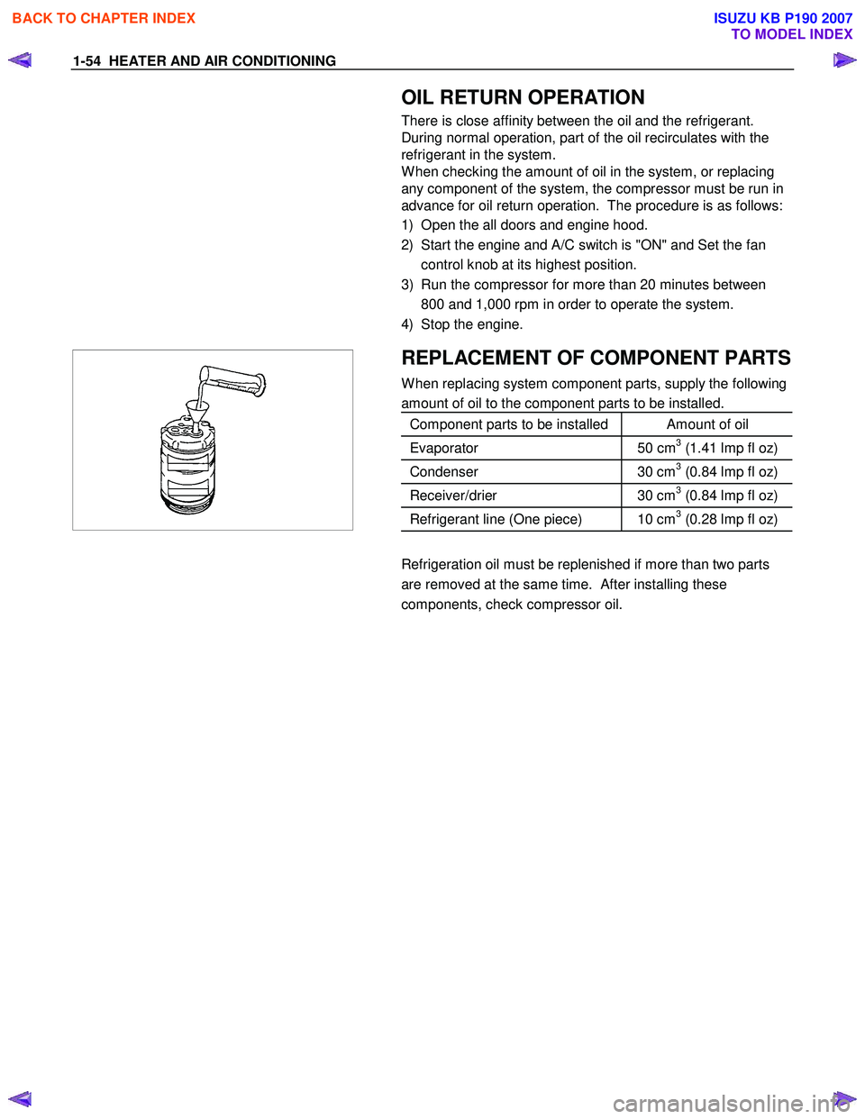
W hen replacing system component parts, supply the following
amount of oil to the component parts to be installed.
Component parts to be installed Amount of oil
Evaporator 50 cm3 (1.41 lmp fl oz)
Condenser 30 cm3 (0.84 lmp fl oz)
Receiver/drier 30 cm3 (0.84 lmp fl oz)
Refrigerant line (One piece) 10 cm3 (0.28 lmp fl oz)
Refrigeration oil must be replenished if more than two parts
are removed at the same time. After installing these
components, check compressor oil.
BACK TO CHAPTER INDEX
TO MODEL INDEX
ISUZU KB P190 2007
Page 268 of 6020
POWER-ASSISTED STEERING SYSTEM 3B-7
Power Steering System Test
Test Procedure
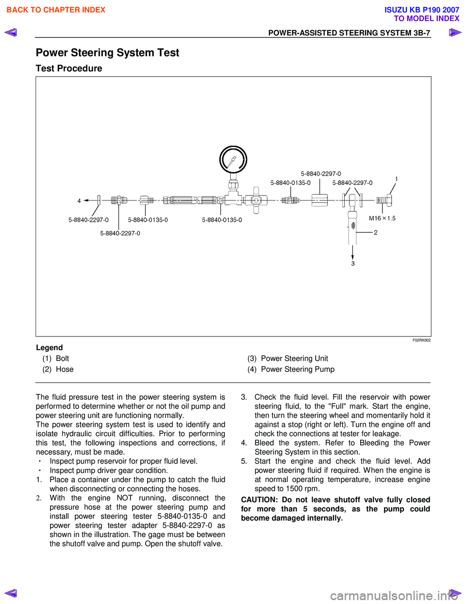
F02RX002
Legend
(1) Bolt
(2) Hose
(3) Power Steering Unit
(4) Power Steering Pump
The fluid pressure test in the power steering system is
performed to determine whether or not the oil pump and
power steering unit are functioning normally.
The power steering system test is used to identify and
isolate hydraulic circuit difficulties. Prior to performing
this test, the following inspections and corrections, i
f
necessary, must be made.
・ Inspect pump reservoir for proper fluid level.
・ Inspect pump driver gear condition.
1. Place a container under the pump to catch the fluid when disconnecting or connecting the hoses.
2. W ith the engine NOT running, disconnect the
pressure hose at the power steering pump and
install power steering tester 5-8840-0135-0 and
power steering tester adapter 5-8840-2297-0 as
shown in the illustration. The gage must be between
the shutoff valve and pump. Open the shutoff valve.
3. Check the fluid level. Fill the reservoir with powe
r
steering fluid, to the "Full" mark. Start the engine,
then turn the steering wheel and momentarily hold it
against a stop (right or left). Turn the engine off and
check the connections at tester for leakage.
4. Bleed the system. Refer to Bleeding the Powe
r
Steering System in this section.
5. Start the engine and check the fluid level. Add power steering fluid if required. W hen the engine is
at normal operating temperature, increase engine
speed to 1500 rpm.
CAUTION: Do not leave shutoff valve fully closed
for more than 5 seconds, as the pump could
become damaged internally.
BACK TO CHAPTER INDEX
TO MODEL INDEX
ISUZU KB P190 2007
Page 269 of 6020
3B-8 POWER-ASSISTED STEERING SYSTEM
6. Fully close the shutoff valve. Record the highest
pressures.
・ If the pressure recorded is within 9800-10300 kPa
(100-105 kg/cm
2/1422-1493psi), the pump is
functioning within its specifications.
・ If the pressure recorded is higher than 10300 kPa
(105 kg/cm
2/1493psi), the valve in the pump is
defective.
・ If the pressure recorded is lower than 9800 kPa
(100 kg/cm
2/1422psi), the valve or the rotating
assembly in the pump is defective.
7. If the pump pressures are within specifications, leave the valve open and turn (or have someone
else turn) the steering wheel fully in both directions.
Record the highest pressures and compare with the
maximum pump pressure recorded in step 6. If this
pressure cannot be built up at either side of the
power steering unit, the power steering unit is
leaking internally and must be replaced.
8. Shut the engine off, remove the testing gauge.
9. Reconnect the pressure hose, check the fluid level and make the needed repairs.
10. If the problem still exists, the steering and front suspension must be thoroughly examined.
Maintenance
The hydraulic system should be kept clean, the fluid
level in the reservoir should be checked at regula
r
intervals and fluid added when required. Refer to
Recommended Fluids and Lubricants in General
Information section for the type of fluid to be used and
the intervals for filling.
If the system contains some dirt, flush it as described in
this section. If it is exceptionally dirty, the pump must be
completely disassembled before further usage. (The
steering unit cannot be disassembled.)
All tubes, hoses, and fittings should be inspected for
leakage at regular intervals. Fittings must be tight. Make
sure the clips, clamps and supporting tubes and hoses
are in place and properly secured.
Power steering hoses and lines must not be twisted,
kinked or tightly bent. Air in the system will cause
spongy action and noisy operation. W hen a hose is
disconnected or when fluid is lost, for any reason, the
system must be bled after refilling. Refer to Bleeding the
Power Steering System in this section.
・ Inspect gear for looseness or damage.
・ Inspect hoses to insure they are not touching an
y
other parts of the vehicle.
・ Inspect fluid level and fill to the proper level.
Fluid Level
1. Run the engine until the power steering fluid
reaches normal operating temperature, about 55 °
C (130 °F), then shut the engine off.
2. Check the level of fluid in the reservoir.
3. If the fluid level is low, add power steering fluid as
specified in General Information to the proper level
and install the receiver cap.
4. W hen checking the fluid level after the steering system has been serviced, air must be bled from
the system. Refer to Bleeding the Power Steering
System in this section.
Bleeding the Power Steering System
W hen a power steering pump or unit has been installed,
or an oil line has been disconnected, the air that has
entered the system must be bled out before the vehicle
is operated. If air is allowed to remain in the powe
r
steering fluid system, noisy and unsatisfactory operation
of the system may result.
Bleeding Procedure
W hen bleeding the system, and any time fluid is added
to the power steering system, be sure to use only powe
r
steering fluid as specified in General Information.
1. Fill the pump fluid reservoir to the proper level and let the fluid settle for at least two minutes.
2. Start the engine and let it run for a few seconds. Do not turn the steering wheel. Then turn the engine
off.
3. Add fluid if necessary.
4. Repeat the above procedure until the fluid level remains constant after running the engine.
5. Raise and support the front end of the vehicle so that the wheels are off the ground.
6. Start the engine. Slowly turn the steering wheel right and left, lightly contacting the wheel stops.
7. Add power steering fluid if necessary.
8. Lower the vehicle, set the steering wheel at the straight forward position after turning it to its full
steer positions 2 or 3 times, and stop the engine.
9. Check the fluid level and refill as required.
10. If the fluid is extremely foamy, allow the vehicle to settle for a few minutes, then repeat the above
procedure.
Flushing the Power Steering System
1. Raise and support the front end of the vehicle off
the ground until the wheels are free to turn.
2. Remove the fluid return line at the pump inlet connector and plug the connector port on the pump.
Direct the line toward a large container to catch the
draining fluid.
3. W hile running the engine at idle, fill the reservoi
r
with new power steering fluid. Turn the steering
wheel in both directions. Do not contact or hold the
steering wheel to the wheel stops. This will cause
the pump to go to pressure relief mode, which ma
y
cause a sudden fluid overflow at the reservoir.
BACK TO CHAPTER INDEX
TO MODEL INDEX
ISUZU KB P190 2007
Page 303 of 6020
3B-42 POWER-ASSISTED STEERING SYSTEM
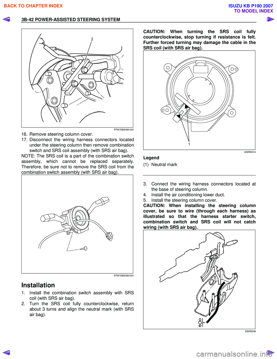
CAUTION: When turning the SRS coil fully
counterclockwise, stop turning if resistance is felt.
Further forced turning may damage the cable in the
SRS coil (with SRS air bag).
826RW 014
Legend
(1) Neutral mark
RTW 73BSH001301
16. Remove steering column cover.
17. Disconnect the wiring harness connectors located under the steering column then remove combination
switch and SRS coil assembly (with SRS air bag).
NOTE: The SRS coil is a part of the combination switch
assembly, which cannot be replaced separately.
Therefore, be sure not to remove the SRS coil from the
combination switch assembly (with SRS air bag).
RTW 73BSH001001
Installation
1. Install the combination switch assembly with SRS coil (with SRS air bag).
2. Turn the SRS coil fully counterclockwise, return about 3 turns and align the neutral mark (with SRS
air bag).
3. Connect the wiring harness connectors located at the base of steering column.
4. Install the air conditioning lower duct.
5. Install the steering column cover.
CAUTION: When installing the steering column
cover, be sure to wire (through each harness) as
illustrated so that the harness starter switch,
combination switch and SRS coil will not catch
wiring (with SRS air bag).
825RS048
BACK TO CHAPTER INDEX
TO MODEL INDEX
ISUZU KB P190 2007
Page 317 of 6020
3B-56 POWER-ASSISTED STEERING SYSTEM
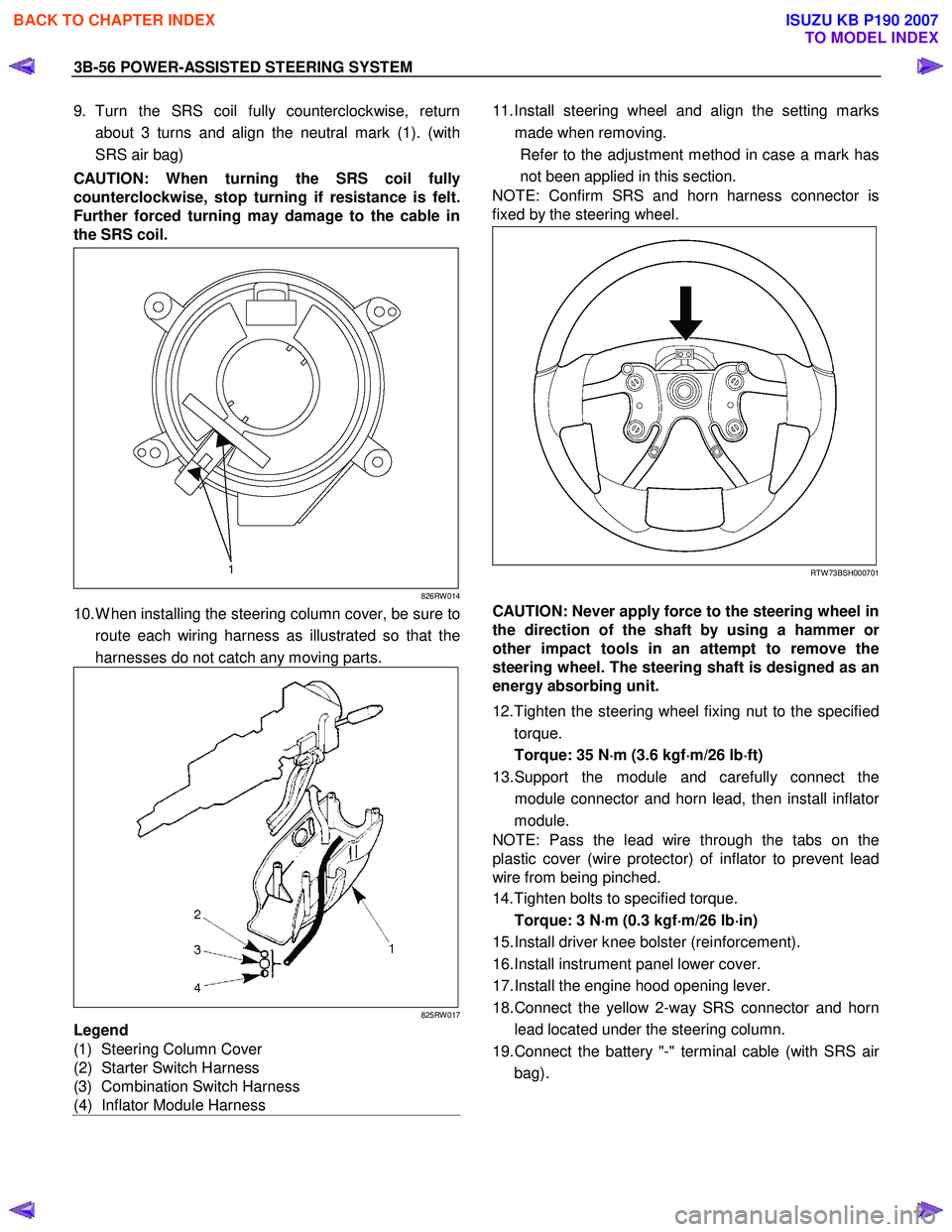
9. Turn the SRS coil fully counterclockwise, return
about 3 turns and align the neutral mark (1). (with
SRS air bag)
CAUTION: When turning the SRS coil fully
counterclockwise, stop turning if resistance is felt.
Further forced turning may damage to the cable in
the SRS coil.
826RW 014
10. W hen installing the steering column cover, be sure to
route each wiring harness as illustrated so that the
harnesses do not catch any moving parts.
825RW 017
Legend
(1) Steering Column Cover
(2) Starter Switch Harness
(3) Combination Switch Harness
(4) Inflator Module Harness
11. Install steering wheel and align the setting marks
made when removing. Refer to the adjustment method in case a mark has
not been applied in this section.
NOTE: Confirm SRS and horn harness connector is
fixed by the steering wheel.
RTW 73BSH000701
CAUTION: Never apply force to the steering wheel in
the direction of the shaft by using a hammer o
r
other impact tools in an attempt to remove the
steering wheel. The steering shaft is designed as an
energy absorbing unit.
12. Tighten the steering wheel fixing nut to the specified torque.
Torque: 35 N ⋅
⋅⋅
⋅
m (3.6 kgf ⋅
⋅⋅
⋅
m/26 lb ⋅
⋅⋅
⋅
ft)
13. Support the module and carefully connect the module connector and horn lead, then install inflato
r
module.
NOTE: Pass the lead wire through the tabs on the
plastic cover (wire protector) of inflator to prevent lead
wire from being pinched.
14. Tighten bolts to specified torque.
Torque: 3 N ⋅
⋅⋅
⋅
m (0.3 kgf ⋅
⋅⋅
⋅
m/26 lb ⋅
⋅⋅
⋅
in)
15. Install driver knee bolster (reinforcement).
16. Install instrument panel lower cover.
17. Install the engine hood opening lever.
18. Connect the yellow 2-way SRS connector and horn lead located under the steering column.
19. Connect the battery "-" terminal cable (with SRS ai
r
bag).
BACK TO CHAPTER INDEX
TO MODEL INDEX
ISUZU KB P190 2007
Page 617 of 6020
5A-24 BRAKE CONTROL SYSTEM
Computer System Service Precautions
The Anti-lock Brake System and Electronic Brake-force
Distribution interfaces directly with the Electronic
Hydraulic Control Unit (EHCU) which is a control
computer that is similar in some regards to the Engine
Control Module. These modules are designed to
withstand normal current draws associated with vehicle
operation. However, care must be taken to avoid
overloading any of the EHCU circuits. In testing for
opens or shorts, do not ground or apply voltage to any
of the circuits unless instructed to do so by the
appropriate diagnostic procedure. These circuits should
only be tested with a high impedance multimeter
5-8840-0366-0 or special tools as described in this
section. Power should never be removed or applied to
any control module with the ignition in the “ON” position.
Before removing or connecting battery cables, fuses or
connectors, always turn the ignition switch to the “OFF”
position.
General Service Precautions
The following are general precautions which should be
observed when servicing and diagnosing the Anti-lock
Brake System and/or other vehicle systems. Failure to
observe these precautions may result in Anti-lock Brake
System and Electronic Brake-force Distribution
damage.
• If welding work is to be performed on the vehicle using an electric arc welder, the EHCU and valve
block connectors should be disconnected before the
welding operation begins.
• The EHCU and valve block connectors should never be connected or disconnected with the
ignition “ON”.
Note:
• If only rear wheels are rotated using jacks or drum tester, the system will diagnose a speed sensor
malfunction and the “ABS and Brake” warning lamp
will illuminate. But actually no trouble exists. W hen
the DTC is not detected and the ABS and BRAKE
warning lamp is on, “How to erase code” is
performed and an ABS and BRAKE warning lamp
are off.
If the battery has been discharged
The engine may stall if the battery has been completely
discharged and the engine is started via jumper cables.
This is because the Anti-lock Brake System (ABS) and
Electronic Brake-force Distribution (EBD) System
requires a large quantity of electricity. In this case, wait
until the battery is recharged, or set the ABS and EBD
to a non-operative state by removing the fuse for the
ABS. After the battery has been recharged, stop the
engine and install the ABS fuse. Start the engine again,
and confirm that the ABS warning Lamp does not light.
Note on Intermittents
As with virtually any electronic system, it is difficult to
identify an intermittent failure. In such a case duplicating
the system malfunction during a test drive or a good
description of vehicle behavior from the customer may
be helpful in locating a “most likely” failed component or
circuit. The symptom diagnosis chart may also be
useful in isolating the failure. Most intermittent
problems are caused by faulty electrical connections or
wiring. W hen an intermittent failure is encountered,
check suspect circuits for:
• Suspected harness damage.
• Poor mating of connector halves or terminals not fully seated in the connector body (backed out).
• Improperly formed or damaged terminals.
Test Driving ABS Complaint Vehicles
If there has been an abnormality in the lighting pattern
of the “ABS” warning lamp, the fault can be located in
accordance with the “DIAGNOSIS BY “ABS” W ARNING
LAMP ILLUMINATION PATTERN”. Although such
problems can be detected by the driver as a vehicle
symptom, it is still necessary to perform a test drive
following the test procedure mentioned below, in order
to reproduce the symptom for problem diagnosis on a
symptom basis:
1. Start the engine and make sure that the “ABS” W /L
goes OFF. If the W /L remains ON, it means that
the Diagnostic Trouble Code (DTC) is stored.
Therefore, read the code and locate the fault.
Note: The DTC cannot be cleared if the vehicle speed
does not exceed about 10km/h (6mph) at DTC, even
though the repair operation is completed.
2. Start the vehicle and accelerate to about 30 km/h (19 mph) or more.
3. Slowly brake and stop the vehicle completely.
4. Then restart the vehicle and accelerate to about 40 km/h (25 mph) or more.
5. Brake at a time so as to actuate the ABS and stop the vehicle.
6. Be cautious of abnormality during the test. If the W /L is actuated while driving, read the DTC and
locate the fault.
7. If the abnormality is not reproduced by the test, make best efforts to reproduce the situation
reported by the customer.
8. If the abnormality has been detected, repair in accordance with the “SYMPTOM DIAGNOSIS”.
Note:
• Be sure to perform a test drive on a wide, even road
with light traffic.
• If an abnormality is detected, be sure to suspend the test and start trouble diagnosis at once.
BACK TO CHAPTER INDEX
TO MODEL INDEX
ISUZU KB P190 2007
Page 629 of 6020
5A-36 BRAKE CONTROL SYSTEM
How to display and erase DTCs:
Note:
• DTCs can be displayed also by TECH 2 use “Diagnostic Trouble Codes” mode.
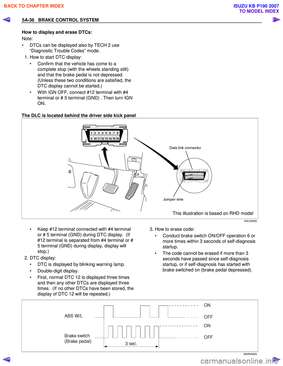
1. How to start DTC display: • Confirm that the vehicle has come to a complete stop (with the wheels standing still)
and that the brake pedal is not depressed.
(Unless these two conditions are satisfied, the
DTC display cannot be started.)
• W ith IGN OFF, connect #12 terminal with #4 terminal or # 5 terminal (GND) . Then turn IGN
ON.
The DLC is located behind the driver side kick panel
This illustration is based on RHD model
350L300005
• Keep #12 terminal connected with #4 terminal or # 5 terminal (GND) during DTC display. (If
#12 terminal is separated from #4 terminal or #
5 terminal (GND) during display, display will
stop.)
2. DTC display: • DTC is displayed by blinking warning lamp.
• Double-digit display.
• First, normal DTC 12 is displayed three times and then any other DTCs are displayed three
times. (If no other DTCs have been stored, the
display of DTC 12 will be repeated.)
3. How to erase code:
• Conduct brake switch ON/OFF operation 6 or more times within 3 seconds of self-diagnosis
startup.
• The code cannot be erased if more than 3 seconds have passed since self-diagnosis
startup, or if self-diagnosis has started with
brake switched on (brake pedal depressed).
B05RW 0005
BACK TO CHAPTER INDEX
TO MODEL INDEX
ISUZU KB P190 2007
Page 730 of 6020
BRAKES 5C-31
ADJUSTMENT PROCEDURE OF BRAKE PEDAL
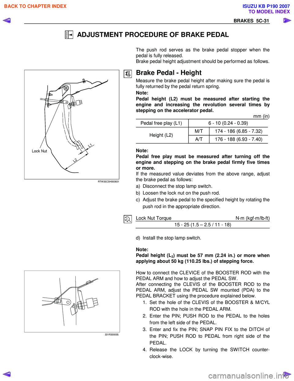
The push rod serves as the brake pedal stopper when the
pedal is fully released.
Brake pedal height adjustment should be performed as follows.
RTW 35CSH000601
Brake Pedal - Height
Measure the brake pedal height after making sure the pedal is
fully returned by the pedal return spring.
Note:
Pedal height (L2) must be measured after starting the
engine and increasing the revolution several times by
stepping on the accelerator pedal. mm (in)
Pedal free play (L1) 6 - 10 (0.24 - 0.39)
M/T 174 - 186 (6.85 - 7.32) Height (L2)
A/T 176 - 188 (6.93 - 7.40)
Note:
Pedal free play must be measured after turning off the
engine and stepping on the brake pedal firmly five times
or more.
If the measured value deviates from the above range, adjust
the brake pedal as follows:
a) Disconnect the stop lamp switch.
b) Loosen the lock nut on the push rod.
c)
Adjust the brake pedal to the specified height by rotating the
push rod in the appropriate direction.
Lock Nut Torque
N⋅m (kgf ⋅m/lb ⋅
⋅⋅
⋅
ft)
15 - 25 (1.5 – 2.5 / 11 - 18)
d) Install the stop lamp switch.
Note:
Pedal height (L
2) must be 57 mm (2.24 in.) or more when
applying about 50 kg (110.25 lbs.) of stepping force.
331R300005
How to connect the CLEVICE of the BOOSTER ROD with the
PEDAL ARM and how to adjust the PEDAL SW .
After connecting the CLEVIS of the BOOSTER ROD to the
PEDAL ARM, adjust the PEDAL SW mounted (PDA) to the
PEDAL BRACKET using the procedure explained below.
1. Set the hole of the CLEVIS of the BOOSTER & M/CYL
ROD with the hole in the PEDAL ARM.
2. Enter the PIN; PUSH ROD to the PEDAL to the holes from the left side of the PEDAL.
3. Enter and fix the PIN; SNAP PIN FIX to the DITCH o
f
the PIN; PUSH ROD to PEDAL from right side of the
PEDAL.
4. Release the LOCK by turning the SW ITCH counter- clock-wise.
BACK TO CHAPTER INDEX
TO MODEL INDEX
ISUZU KB P190 2007
Page 832 of 6020
ENGINE MECHANICAL 6A – 27
111R300001
COOLING SYSTEM
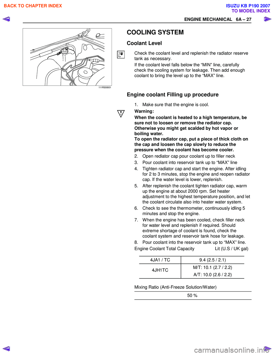
Coolant Level
Check the coolant level and replenish the radiator reserve
tank as necessary.
If the coolant level falls below the “MIN” line, carefully
check the cooling system for leakage. Then add enough
coolant to bring the level up to the “MAX” line.
Engine coolant Filling up procedure
1. Make sure that the engine is cool.
Warning:
When the coolant is heated to a high temperature, be
sure not to loosen or remove the rediator cap.
Otherwise you might get scalded by hot vapor or
boiling water.
To open the radiator cap, put a piece of thick cloth on
the cap and loosen the cap slowly to reduce the
pressure when the coolant has become cooler.
2. Open rediator cap pour coolant up to filler neck
3. Pour coolant into reservoir tank up to “MAX” line
4. Tighten radiator cap and start the engine. After idling for 2 to 3 minutes, stop the engine and reopen radiator
cap. If the water level is lower, replenish.
5. After replenish the coolant tighten radiator cap, warm up the engine at about 2000 rpm. Set heater
adjustment to the highest temperature position, and let
the coolant circulate also into heater water system.
6. Check to see the thermometer, continuously idling 5 minutes and stop the engine.
7. W hen the engine has been cooled, check filler neck for water level and replenish if required. Should
extreme shortage of coolant is found, check the
coolant system and reservoir tank hose for leakage.
8. Pour coolant into the reservoir tank up to “MAX” line.
Engine Coolant Total Capacity Lit (U.S / UK gal)
4JA1 / TC 9.4 (2.5 / 2.1)
4JH1TC M/T: 10.1 (2.7 / 2.2)
A/T: 10.0 (2.6 / 2.2)
Mixing Ratio (Anti-Freeze Solution/W ater)
50 %
BACK TO CHAPTER INDEX
TO MODEL INDEX
ISUZU KB P190 2007
Page 846 of 6020
ENGINE MECHANICAL 6A – 41
Coolant Replenishment
Warning:
When the coolant is heated to a high temperature, be
sure not to loosen or remove the rediator cap.
Otherwise you might get scalded by hot vapor or
boiling water.
To open the radiator cap, put a piece of thick cloth on
the cap and loosen the cap slowly to reduce the
pressure when the coolant has become cooler.
1. Open rediator cap pour coolant up to filler neck
2. Pour coolant into reservoir tank up to "MAX" line
3. Tighten radiator cap and start the engine. After idling for 2 to 3 minutes, stop the engine and reopen radiator
cap. If the water level is lower, replenish.
4. After replenish the coolant tighten radiator cap, warm up the engine at about 2000 rpm. Set heater
adjustment to the highest temperature position, and let
the coolant circulate also into heater water system.
5. Check to see the thermometer, continuously idling 5 minutes and stop the engine.
6. W hen the engine has been cooled, check filler neck for water level and replenish if required. Should extreme
shortage of coolant is found, check the coolant system
and reservoir tank hose for leakage.
7. Pour coolant into the reservoir tank up to "MAX" line.
Coolant Capacity lit (US/UK gal)
4JA1 / TC 9.4 (2.5 / 2.1)
4JH1TC M/T: 10.1 (2.7 / 2.2)
A/T: 10.0 (2.6 / 2.2)
Engine Warm-Up
After completing the required maintenance procedures,
start the engine and allow it to idle until it is warm.
Check the following:
1. Engine idling speed.
2. Engine noise level.
3. Engine lubricating system and cooling system. Carefully check for oil and coolant leakage.
4. Clutch engagement.
5. Transmission operation.
6. Indicator warning light operation.
BACK TO CHAPTER INDEX
TO MODEL INDEX
ISUZU KB P190 2007