width ISUZU KB P190 2007 Workshop Workshop Manual
[x] Cancel search | Manufacturer: ISUZU, Model Year: 2007, Model line: KB P190, Model: ISUZU KB P190 2007Pages: 6020, PDF Size: 70.23 MB
Page 2841 of 6020
Engine Mechanical – V6 Page 6A1–64
Page 6A1–64
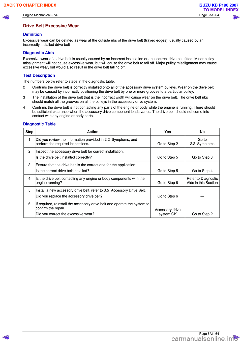
Drive Belt Excessive Wear
Definition
Excessive wear can be defined as wear at the outside ribs of the drive belt (frayed edges), usually caused by an
incorrectly installed drive belt
Diagnostic Aids
Excessive wear of a drive belt is usually caused by an incorre ct installation or an incorrect drive belt fitted. Minor pulley
misalignment will not cause excessive wear, but will cause the drive belt to fall off. Major pulley misalignment may cause
excessive wear, but would also re sult in the drive belt falling off.
Test Description
The numbers below refer to steps in the diagnostic table.
2 Confirms the drive belt is correctly installed onto all of the accessory drive system pulleys. Wear on the drive belt
may be caused by incorrectly positioning the drive belt by one or more grooves to a particular pulley.
3 The installation of the drive belt that is the incorrect width will cause wear on the drive belt. The drive belt ribs
should match all the grooves on all the pu lleys in the accessory drive system.
4 Confirms the drive belt is not cont acting any parts of the engine or body wh ile the engine is running. There should
be sufficient clearance when the accessory drive component loads varies. The drive belt should not come into
contact with any engine or body parts.
Diagnostic Table
Step Action Yes No
1
Did you review the information provided in 2.2 Symptoms, and
perform the required inspections. Go to Step 2 Go to
2.2 Symptoms
2 Inspect the accessory drive belt for correct installation.
Is the drive belt installed correctly? Go to Step 5 Go to Step 3
3 Ensure that the drive belt is
the correct one for the application.
Is the correct drive belt installed? Go to Step 5 Go to Step 4
4 Is the drive belt contacting any engine or body components with the
engine running? Go to Step 6 Refer to Diagnostic
Aids in this Section
5 Install a new accessory drive belt, re fer to 3.5 Accessory Drive Belt.
Did you replace the accessory drive belt? Go to Step 6 —
6 If required, reinstall the accessory drive belt and operate the system to
confirm the repair.
Did you correct the excessive wear? Accessory drive
system OK Go to Step 2
BACK TO CHAPTER INDEX
TO MODEL INDEX
ISUZU KB P190 2007
Page 2983 of 6020
Engine Mechanical – V6 Page 6A1–206
Page 6A1–206
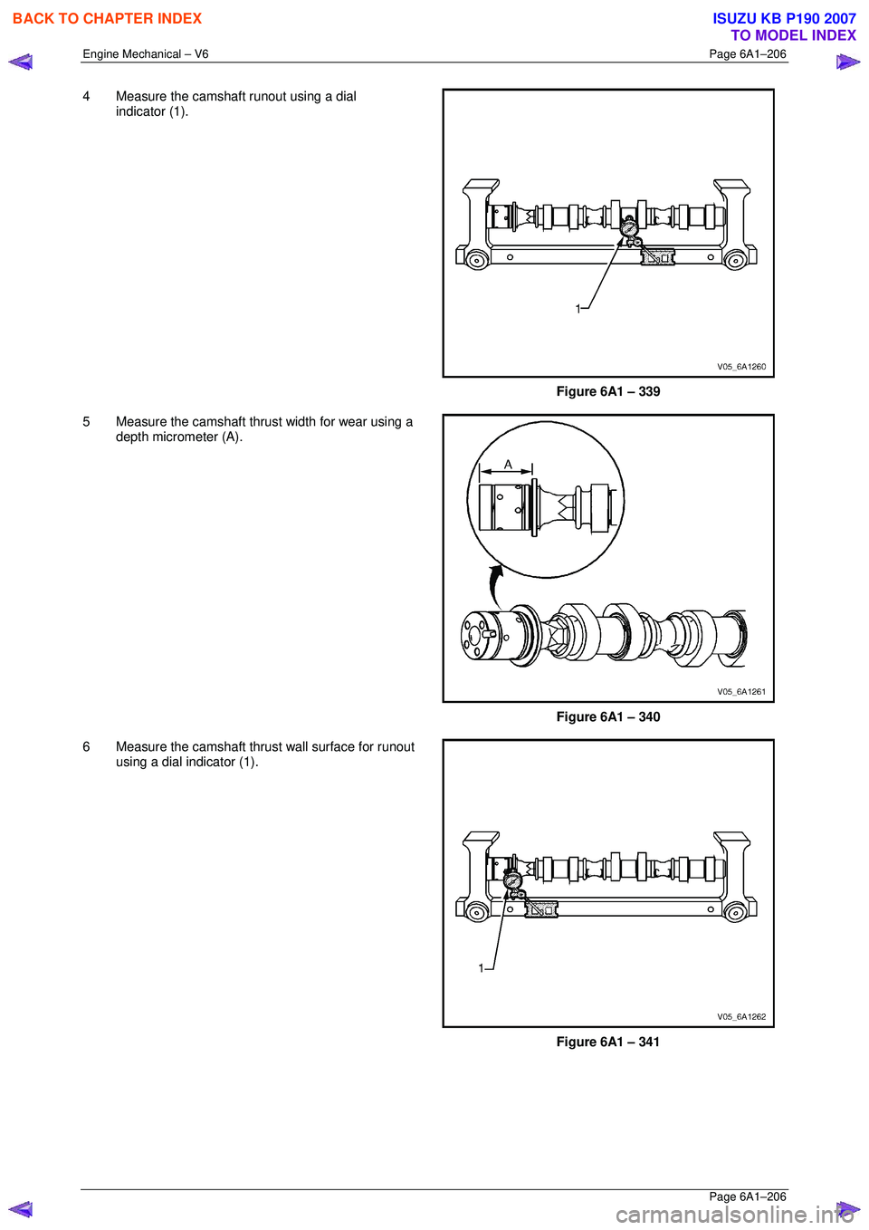
4 Measure the camshaft runout using a dial
indicator (1).
Figure 6A1 – 339
5 Measure the camshaft thrust width for wear using a depth micrometer (A).
Figure 6A1 – 340
6 Measure the camshaft thrust wall surface for runout using a dial indicator (1).
Figure 6A1 – 341
BACK TO CHAPTER INDEX
TO MODEL INDEX
ISUZU KB P190 2007
Page 2991 of 6020

Engine Mechanical – V6 Page 6A1–214
Page 6A1–214
Reinstall
1 Apply a liberal amount of commercially available
camshaft / lifter prelube or equivalent to the pivot
pocket (1), roller (2) and valve slot (3) areas of the
camshaft followers.
Figure 6A1 – 360
2 Place the rocker arm in position on the valve tip and stationary hydraulic lash adjuster (SHLA). The
rounded head end of the arm seats on the SHLA
while the flat end seats on the valve tip.
CAUTION
• The rocker arm (1) must be positioned
squarely on the valve tip so the full width
of the roller will completely contact the
camshaft lobe.
• If the rocker arms are being reused, they
must be reinstalled in their original
location.
3 Clean the camshaft journals and carriers with a clean, lint-free cloth.
4 Reinstall the camshafts, refer to 3.19 Camshaft.
Figure 6A1 – 361
BACK TO CHAPTER INDEX
TO MODEL INDEX
ISUZU KB P190 2007
Page 3003 of 6020

Engine Mechanical – V6 Page 6A1–226
Page 6A1–226
Valve Visual Inspection Procedure
1 Inspect the valve for damage from the head to tip for
the following conditions:
• pitting in the valve seat area (1),
• lack of valve margin (2),
• bending in the valve stem (3),
• pitting or excessive wear in the stem (4),
• worn valve key grooves (5), and
• worn valve tip (6).
2 Replace the valve if any of these conditions exist.
Figure 6A1 – 381
Valve Measurement and Reconditioning Overview
Correct valve service is critical to engine performance. Therefore, all detailed measurement procedures must be followed
to identify components that are out of specification. If the measurement procedures reveal t he valve or valve seat must
be reconditioned, it is critical to perform t he measurement procedures after reconditioning.
Valve Seat Width Measurement Procedure
1 Measure the valve seat (1) width in the cylinder head
using a scale (2).
Figure 6A1 – 382
BACK TO CHAPTER INDEX
TO MODEL INDEX
ISUZU KB P190 2007
Page 3004 of 6020
Engine Mechanical – V6 Page 6A1–227
Page 6A1–227
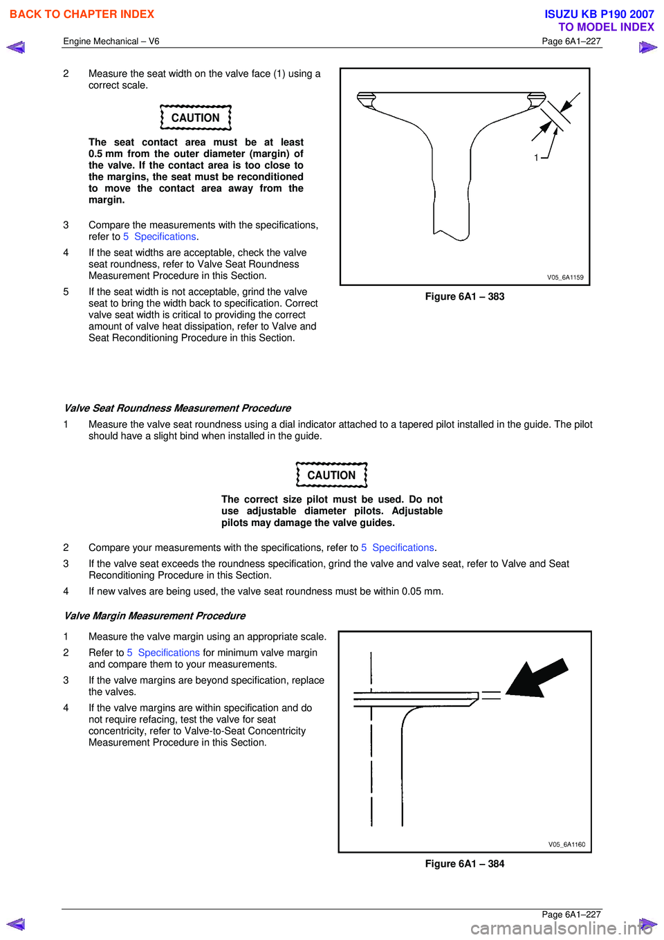
2 Measure the seat width on the valve face (1) using a
correct scale.
CAUTION
The seat contact area must be at least
0.5 mm from the outer diameter (margin) of
the valve. If the contact area is too close to
the margins, the seat must be reconditioned
to move the contact area away from the
margin.
3 Compare the measurements with the specifications,
refer to 5 Specifications .
4 If the seat widths are a cceptable, check the valve
seat roundness, refer to Valve Seat Roundness
Measurement Procedure in this Section.
5 If the seat width is not acceptable, grind the valve
seat to bring the width back to specification. Correct
valve seat width is critical to providing the correct
amount of valve heat dissipat ion, refer to Valve and
Seat Reconditioning Procedure in this Section.
Figure 6A1 – 383
Valve Seat Roundness Measurement Procedure
1 Measure the valve seat roundness using a dial indicator a ttached to a tapered pilot installed in the guide. The pilot
should have a slight bind w hen installed in the guide.
CAUTION
The correct size pilot must be used. Do not
use adjustable diameter pilots. Adjustable
pilots may damage the valve guides.
2 Compare your measurements with the specifications, refer to 5 Specifications.
3 If the valve seat exceeds the roundne ss specification, grind the valve and valve seat, refer to Valve and Seat
Reconditioning Procedure in this Section.
4 If new valves are being used, the valv e seat roundness must be within 0.05 mm.
Valve Margin Measurement Procedure
1 Measure the valve margin using an appropriate scale.
2 Refer to 5 Specifications for minimum valve margin
and compare them to your measurements.
3 If the valve margins are beyond specification, replace the valves.
4 If the valve margins are within specification and do not require refacing, test the valve for seat
concentricity, refer to Valve-to-Seat Concentricity
Measurement Procedure in this Section.
Figure 6A1 – 384
BACK TO CHAPTER INDEX
TO MODEL INDEX
ISUZU KB P190 2007
Page 3005 of 6020
Engine Mechanical – V6 Page 6A1–228
Page 6A1–228
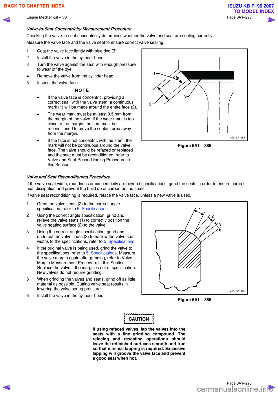
Valve-to-Seat Concentricity Measurement Procedure
Checking the valve-to-seat concentricity determines whether the valve and seat are sealing correctly.
Measure the valve face and the valve s eat to ensure correct valve sealing.
1 Coat the valve face lightly with blue dye (3).
2 Install the valve in the cylinder head.
3 Turn the valve against the seat with enough pressure to wear off the dye.
4 Remove the valve from the cylinder head.
5 Inspect the valve face.
NOTE
• If the valve face is concentric, providing a
correct seal, with the valve stem, a continuous
mark (1) will be made around the entire face (2).
• The wear mark must be at least 0.5 mm from
the margin of the valve. If the wear mark is too
close to the margin, the seat must be
reconditioned to move the contact area away
from the margin.
• If the face is not concentric with the stem, the
mark will not be continuous around the valve
face. The valve should be refaced or replaced
and the seat must be reconditioned, refer to
Valve and Seat Reconditioning Procedure in
this Section.
Figure 6A1 – 385
Valve and Seat Reconditioning Procedure
If the valve seat width, roundness or conc entricity are beyond specifications, grind the seats in order to ensure correct
heat dissipation and prevent the bu ild up of carbon on the seats.
If valve seat reconditioning is required, reface the valve face, unless a new valve is used.
1 Grind the valve seats (2) to the correct angle specification, refer to 5 Specifications.
2 Using the correct angle specification, grind and
relieve the valve seats (1) to correctly position the
valve seating surface (2) to the valve.
3 Using the correct angle specification, grind and
undercut the valve seats (3) to narrow the valve seat
widths to the specifications, refer to 5 Specifications.
4 If the original valve is being used, grind the valve to the specifications, refer to 5 Specifications. Measure
the valve margin again after grinding, refer to Valve
Margin Measurement Procedure in this Section.
Replace the valve if the margin is out of specification.
New valves do not require grinding.
5 When grinding the valves and seats, grind off as little material as possible. Cutti ng valve seat results in
lowering the valve spring pressure.
6 Install the valve in the cylinder head.
Figure 6A1 – 386
CAUTION
If using refaced valves, lap the valves into the
seats with a fine grinding compound. The
refacing and reseati ng operations should
leave the refinished surfaces smooth and true
so that minimal lapping is required. Excessive
lapping will groove the valve face and prevent
a good seat when hot.
BACK TO CHAPTER INDEX
TO MODEL INDEX
ISUZU KB P190 2007
Page 3006 of 6020

Engine Mechanical – V6 Page 6A1–229
Page 6A1–229
NOTE
• Clean any remaining lapping compound from
the valve and seat with solvent and
compressed air prior to final assembly.
• If fitting new valves, do not lap the valves
under any condition.
7 After obtaining the correct valve seat width in the cylinder head, measure the valve stem height, refer to Valve
Stem Height Measurement Pr ocedure in this Section.
8 If the valve stem height is acceptabl e, test the seats for concentricity, refer to Valve-to-Seat Concentricity
Measurement Procedure in this Section.
Valve Stem Height Measurement Procedure
CAUTION
To determine the valve stem height
measurement, measure from the valve
spring seat to the valve spring retainer.
1 Install the valve into the valve guide.
2 Ensure the valve is seated to the valve seat.
3 Install the valve stem oil seal.
4 Install the valve spring retainer and valve stem keys.
5 Measure the distance (1 ) between the cylinder head
to the bottom of the valve spring retainer, refer to
5 Specifications .
6 If the maximum height spec ification is exceeded, a
new valve should be installed and the valve stem
height re-measured.
Figure 6A1 – 387
CAUTION
Do not grind the valve stem tip. The tip of the
valve is hardened and grinding the tip will
eliminate the hardened surface causing
premature wear and possible engine damage.
CAUTION
Do not use shims to adjust valve stem height.
The use of shims will cause the valve spring
to bottom out before the camshaft lobe is at
peak lift and engine damage could result.
7 If the valve stem height still exceeds the maximum height specification, the cylinder head must be replaced.
BACK TO CHAPTER INDEX
TO MODEL INDEX
ISUZU KB P190 2007
Page 3042 of 6020
Engine Mechanical – V6 Page 6A1–265
Page 6A1–265
4.5 Pistons, Pins, Rings, Connecting Rods
and Big-end Bearings
Remove
1 Remove the engine assembly, refer to 4.1 Engine .
2 Remove both cylinder head assemblies, refer to 3.22 Cylinder Head Assembly.
3 Remove the oil pan assembly, refer to 4.2 Oil Pan and Oil Pump Suction Pipe Assembly .
4 Mark the top of the piston being remo ved to identify its specific bore.
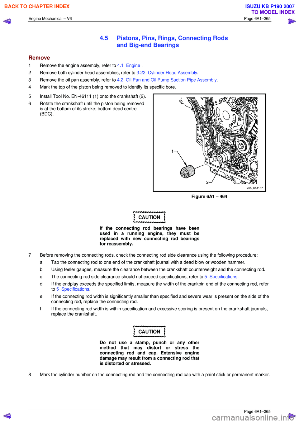
5 Install Tool No. EN-46111 (1) onto the crankshaft (2).
6 Rotate the crankshaft until the piston being removed is at the bottom of its stroke; bottom dead centre
(BDC).
Figure 6A1 – 464
CAUTION
If the connecting rod bearings have been
used in a running engine, they must be
replaced with new connecting rod bearings
for reassembly.
7 Before removing the connecting rods, check the connec ting rod side clearance using the following procedure:
a Tap the connecting rod to one end of the cranks haft journal with a dead blow or wooden hammer.
b Using feeler gauges, measure the clearance between the crankshaft counterweight and the connecting rod.
c The connecting rod side clearance should not exceed specifications, refer to 5 Specifications.
d If the endplay exceeds the specified limits, measure the width of the crankpin end of the connecting rod, refer
to 5 Specifications .
e If the connecting rod width is significantly smaller than specified and severe wear is present on the side of the
connecting rod, replac e the connecting rod.
f If the connecting rod width is within specification and excessive scoring is present on the crankshaft journals,
replace the crankshaft.
CAUTION
Do not use a stamp, punch or any other
method that may distort or stress the
connecting rod and cap. Extensive engine
damage may result from a connecting rod that
is distorted or stressed.
8 Mark the cylinder number on the connec ting rod and the connecting rod cap with a paint stick or permanent marker.
BACK TO CHAPTER INDEX
TO MODEL INDEX
ISUZU KB P190 2007
Page 3047 of 6020
Engine Mechanical – V6 Page 6A1–270
Page 6A1–270
Piston Measurement
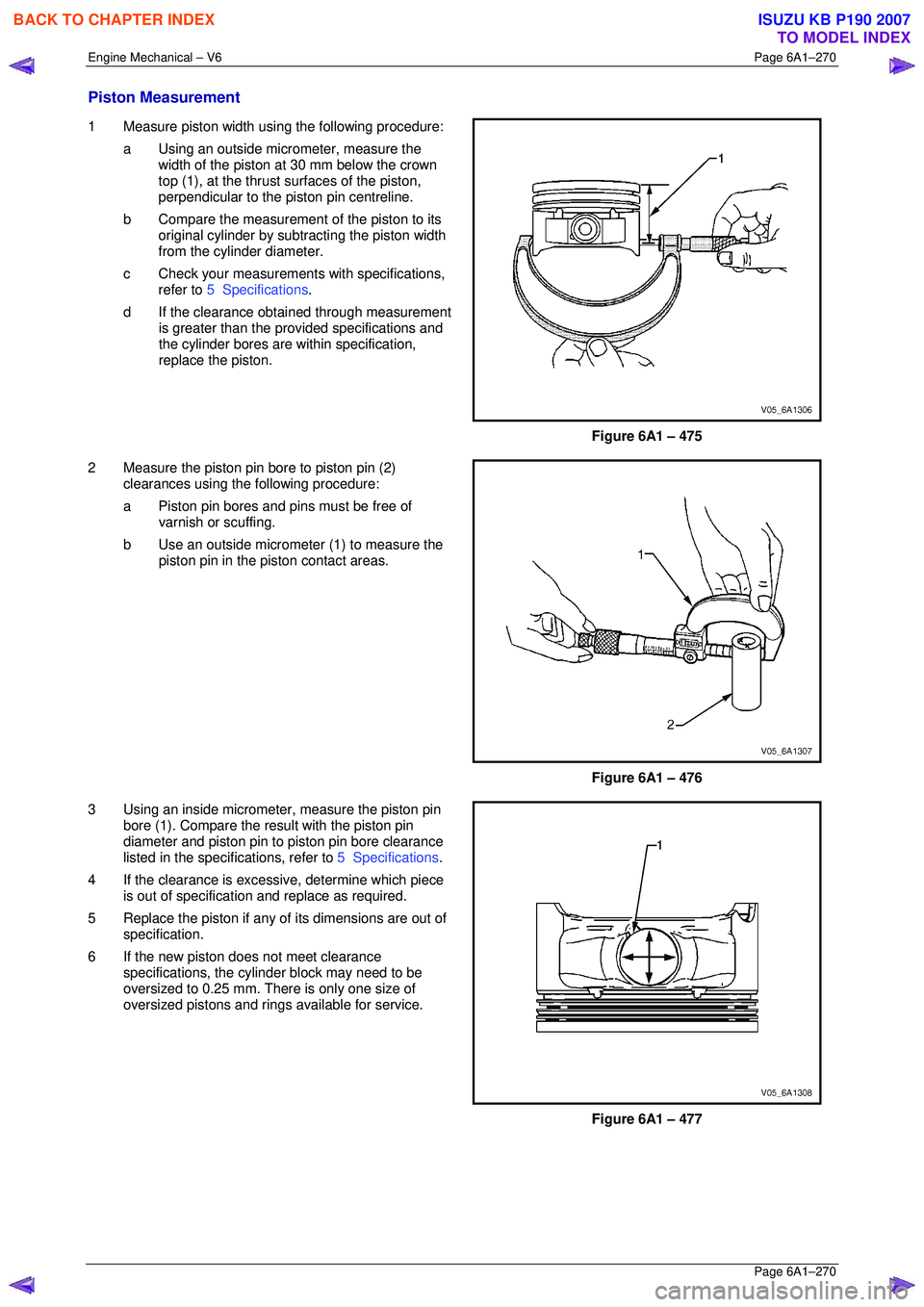
1 Measure piston width using the following procedure:
a Using an outside micr ometer, measure the
width of the piston at 30 mm below the crown
top (1), at the thrust surfaces of the piston,
perpendicular to the piston pin centreline.
b Compare the measurement of the piston to its
original cylinder by subtracting the piston width
from the cylinder diameter.
c Check your measurements with specifications, refer to 5 Specifications .
d If the clearance obtai ned through measurement
is greater than the prov ided specifications and
the cylinder bores are wi thin specification,
replace the piston.
Figure 6A1 – 475
2 Measure the piston pin bore to piston pin (2) clearances using the following procedure:
a Piston pin bores and pins must be free of varnish or scuffing.
b Use an outside micrometer (1) to measure the
piston pin in the piston contact areas.
Figure 6A1 – 476
3 Using an inside micrometer , measure the piston pin
bore (1). Compare the resu lt with the piston pin
diameter and piston pin to piston pin bore clearance
listed in the specifications, refer to 5 Specifications.
4 If the clearance is excessive, determine which piece is out of specification and replace as required.
5 Replace the piston if any of its dimensions are out of
specification.
6 If the new piston does not meet clearance specifications, the cylinder block may need to be
oversized to 0.25 mm. There is only one size of
oversized pistons and rings available for service.
Figure 6A1 – 477
BACK TO CHAPTER INDEX
TO MODEL INDEX
ISUZU KB P190 2007
Page 3056 of 6020
Engine Mechanical – V6 Page 6A1–279
Page 6A1–279
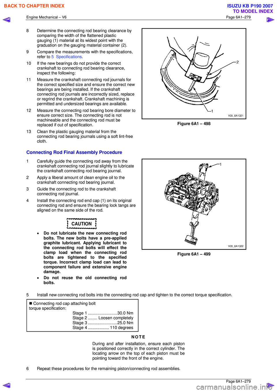
8 Determine the connecting rod bearing clearance by
comparing the width of the flattened plastic
gauging (1) material at its widest point with the
graduation on the gauging mate rial container (2).
9 Compare the measurements with the specifications,
refer to 5 Specifications .
10 If the new bearings do not provide the correct crankshaft to connecting rod bearing clearance,
inspect the following:
11 Measure the crankshaft connecting rod journals for the correct specified size and ensure the correct new
bearings are being installed. If the crankshaft
connecting rod journals are in correctly sized, replace
or regrind the crankshaft. Crankshaft machining is
permitted and undersized bearings are available.
12 Measure the connecting rod bearing bore diameter to
ensure correct size. The connecting rod is not
machineable and the connecting rod must be
replaced if out of specification.
13 Clean the plastic gauging material from the connecting rod bearing journals using a soft lint-free
cloth.
Figure 6A1 – 498
Connecting Rod Final Assembly Procedure
1 Carefully guide the connecting rod away from the crankshaft connecting rod journal slightly to lubricate
the crankshaft connecting rod bearing journal.
2 Apply a liberal amount of clean engine oil to the crankshaft connecting rod bearing journal.
3 Guide the connecting rod to the crankshaft connecting rod journal.
4 Install the connecting rod end cap (1) on its original
connecting rod and ensure t he bearing lock tangs are
aligned on the same side of the rod.
CAUTION
• Do not lubricate the new connecting rod
bolts. The new bolts have a pre-applied
graphite lubricant. Applying lubricant to
the connecting rod bolts will effect the
clamp load when the connecting rod
bolts are tightened to the specified
torque. Incorrect clamp load can lead to
component failure and extensive engine
damage.
• Do not reuse the old connecting rod
bolts.
Figure 6A1 – 499
5 Install new connecting rod bolts into the connecting r od cap and tighten to the correct torque specification.
�„ Connecting rod cap attaching bolt
torque specification:
Stage 1 .........................30.0 Nm
Stage 2 ........Loosen completely
Stage 3 .........................25.0 Nm
Stage 4 ..................110 degrees
NOTE
During and after installation, ensure each piston
is positioned correctly in the correct cylinder. The
locating arrow on the top of each piston must be
pointing toward the front of the engine.
6 Repeat these procedures for the rema ining piston/connecting rod assemblies.
BACK TO CHAPTER INDEX
TO MODEL INDEX
ISUZU KB P190 2007