width ISUZU KB P190 2007 Workshop Manual PDF
[x] Cancel search | Manufacturer: ISUZU, Model Year: 2007, Model line: KB P190, Model: ISUZU KB P190 2007Pages: 6020, PDF Size: 70.23 MB
Page 3064 of 6020
Engine Mechanical – V6 Page 6A1–287
Page 6A1–287
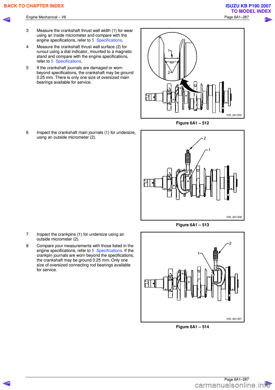
3 Measure the crankshaft thrust wall width (1) for wear
using an inside micrometer and compare with the
engine specifications, refer to 5 Specifications.
4 Measure the crankshaft thrust wall surface (2) for runout using a dial indica tor, mounted to a magnetic
stand and compare with t he engine specifications,
refer to 5 Specifications .
5 If the crankshaft journals are damaged or worn beyond specifications, t he crankshaft may be ground
0.25 mm. There is only one size of oversized main
bearings available for service.
Figure 6A1 – 512
6 Inspect the crankshaft main journals (1) for undersize, using an outside micrometer (2).
Figure 6A1 – 513
7 Inspect the crankpins (1) for undersize using an outside micrometer (2).
8 Compare your measurements with those listed in the
engine specifications, refer to 5 Specifications. If the
crankpin journals are worn beyond the specifications,
the crankshaft may be ground 0.25 mm. Only one
size of oversized connecting rod bearings available
for service.
Figure 6A1 – 514
BACK TO CHAPTER INDEX
TO MODEL INDEX
ISUZU KB P190 2007
Page 3067 of 6020
Engine Mechanical – V6 Page 6A1–290
Page 6A1–290
NOTE
Do not rotate the crankshaft.
9 Allow the assembly to sit for 2 minutes.
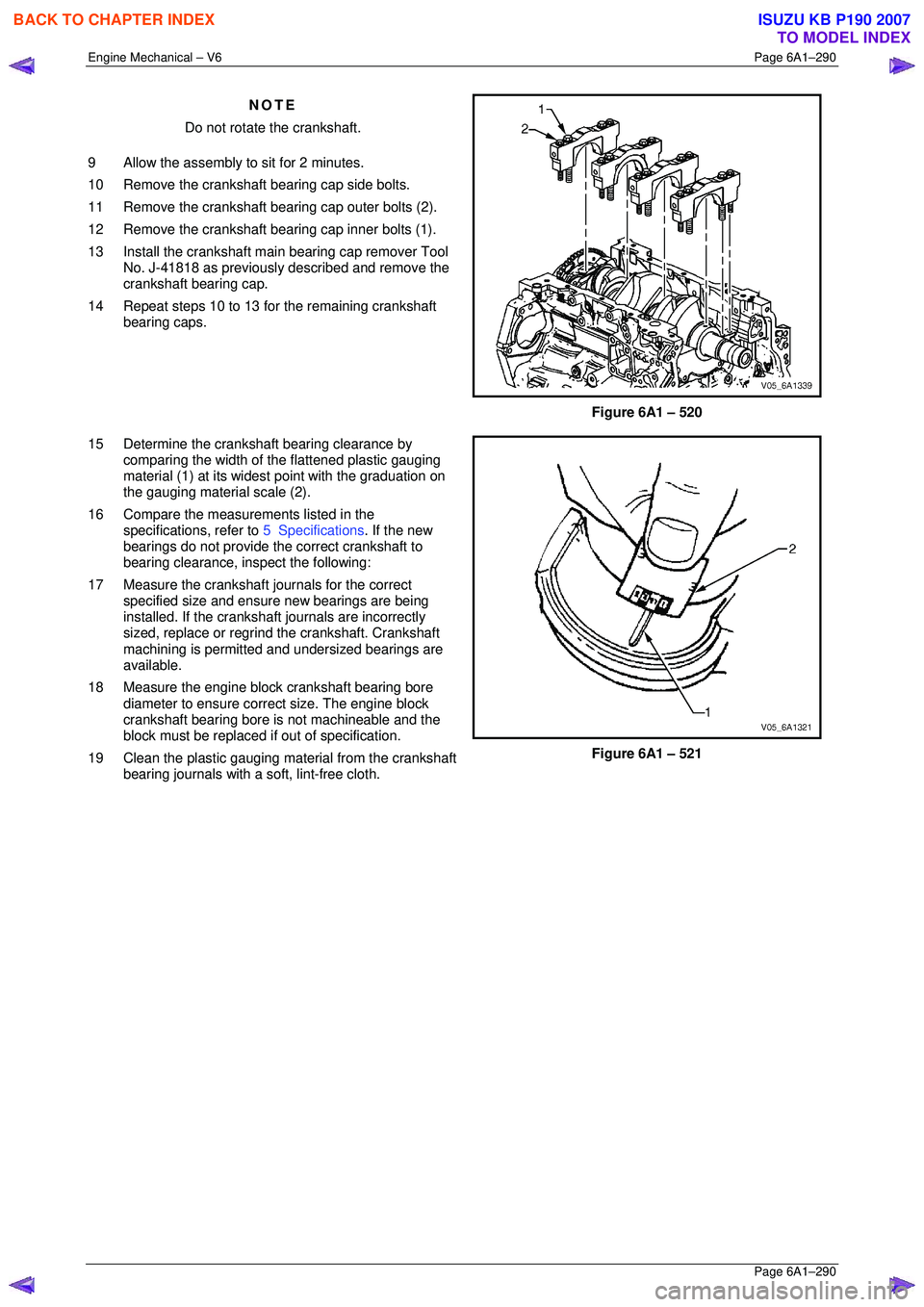
10 Remove the crankshaft bearing cap side bolts.
11 Remove the crankshaft bearing cap outer bolts (2).
12 Remove the crankshaft bearing cap inner bolts (1).
13 Install the crankshaft main bearing cap remover Tool No. J-41818 as previously described and remove the
crankshaft bearing cap.
14 Repeat steps 10 to 13 for the remaining crankshaft bearing caps.
Figure 6A1 – 520
15 Determine the crankshaft bearing clearance by comparing the width of the flattened plastic gauging
material (1) at its widest point with the graduation on
the gauging material scale (2).
16 Compare the measur ements listed in the
specifications, refer to 5 Specifications. If the new
bearings do not provide the correct crankshaft to
bearing clearance, inspect the following:
17 Measure the crankshaft journals for the correct specified size and ensure new bearings are being
installed. If the crankshaft journals are incorrectly
sized, replace or regrind the crankshaft. Crankshaft
machining is permitted and undersized bearings are
available.
18 Measure the engine block crankshaft bearing bore diameter to ensure correct size. The engine block
crankshaft bearing bore is not machineable and the
block must be replaced if out of specification.
19 Clean the plastic gauging material from the crankshaft bearing journals with a soft, lint-free cloth.
Figure 6A1 – 521
BACK TO CHAPTER INDEX
TO MODEL INDEX
ISUZU KB P190 2007
Page 3124 of 6020

Engine Mechanical – V6 Page 6A1–347
Page 6A1–347
5 Specifications
General
Engine Type .................................................................................................................... .... V6
Bank An gle ..................................................................................................................... .... 60°
Displacement ............................................................................................ 3.6 litre (3,565 cm3)
Bore ........................................................................................................................... .... 94 mm
Stroke ......................................................................................................................... 85.6 mm
Compression Ratio......................................................................................................... 10. 2:1
Cranking Speed at 40 °C .............................................................................................80 r.p.m.
Spark Plug Gap ............................................................................................................ 1.1 mm
Firing Order ............................................................................................................ 1- 2-3-4-5-6
Cylinder Block
Cylinder Bore Diame ter ........................................................................... 93.992 – 94.008 mm
Cylinder Out-of-Round – Pr oduction Maximum ........................................................ 0.013 mm
Crankshaft Main bearing bor e Diameter .................................................. 72. 867 – 72.881 mm
Cylinder Head Deck Surf ace Flatness ........................................................................ 0. 05 mm
Crankshaft
Connecting Rod Journal Diameter........................................................... 55. 992 – 56.008 mm
Connecting Rod Journa l Out-of-Round..................................................................... 0.005 mm
Connecting Rod Jour nal Taper................................................................................ .0. 005 mm
Connecting Rod Journal Width (Production)........................................................... 22.000 mm
Connecting Rod Journal Width (Service limit)......................................... 21. 920 – 22.080 mm
Crankshaft End Pl ay .................................................................................... 0.100 – 0.330 mm
Crankshaft Main Bearing Clearance ............................................................ 0.010 – 0.060 mm
Crankshaft Main Journal Diameter......................................................... .67. 992 – 68.008 mm
Crankshaft Main Journa l Out-of-Round .................................................................... 0.005 mm
Crankshaft Main Journal Taper ............................................................................... .0. 005 mm
Crankshaft Main Journal Width, #2, 4 (Pr oduction)....................................................... 24 mm
Crankshaft Main Journal Width, #2, 4 (Service)...................................... 23. 900 – 24.100 mm
Crankshaft Main Journal Wi dth, #3 (Production) .................................................... 24.400 mm
Crankshaft Main Journal Width, #3 (Service).......................................... 24. 360 – 24.440 mm
Crankshaft Main Journal Thru st Wall Runout.............................................. 0.
000 – 0.040 mm
Crankshaft Main Journal Thru st Wall Square.............................................. 0. 000 – 0.010 mm
Crankshaft Rear Fl ange Runout............................................................................... 0. 025 mm
Crankshaft Reluctor Ring Ru nout - Maximum .......................................................... 1.500 mm
Crankshaft Thrust Bearin g Clearance.......................................................... 0. 076 – 0.305 mm
Crankshaft Thrust Su rface Runout........................................................................... 0. 040 mm
Crankshaft Thrust Surface – Height Diameter ........................................................ 95.000 mm
Connecting Rod
Connecting Rod Length - Bore Centre-to-Centre ................................................. 150.400 mm
Connecting Rod Bore Diameter - Bearing End........................................ 59. 620 – 59.636 mm
Connecting Rod Bore Diamet er - Pin End............................................... 24. 007 – 24.021 mm
Connecting Rod Width ........................................................................................... 21.775 mm
Connecting Rod Side Cl earance.................................................................. 0.095 – 0.355 mm
Connecting Rod Bearing Clearance ............................................................ 0.010 – 0.070 mm
BACK TO CHAPTER INDEX
TO MODEL INDEX
ISUZU KB P190 2007
Page 3125 of 6020
Engine Mechanical – V6 Page 6A1–348
Page 6A1–348
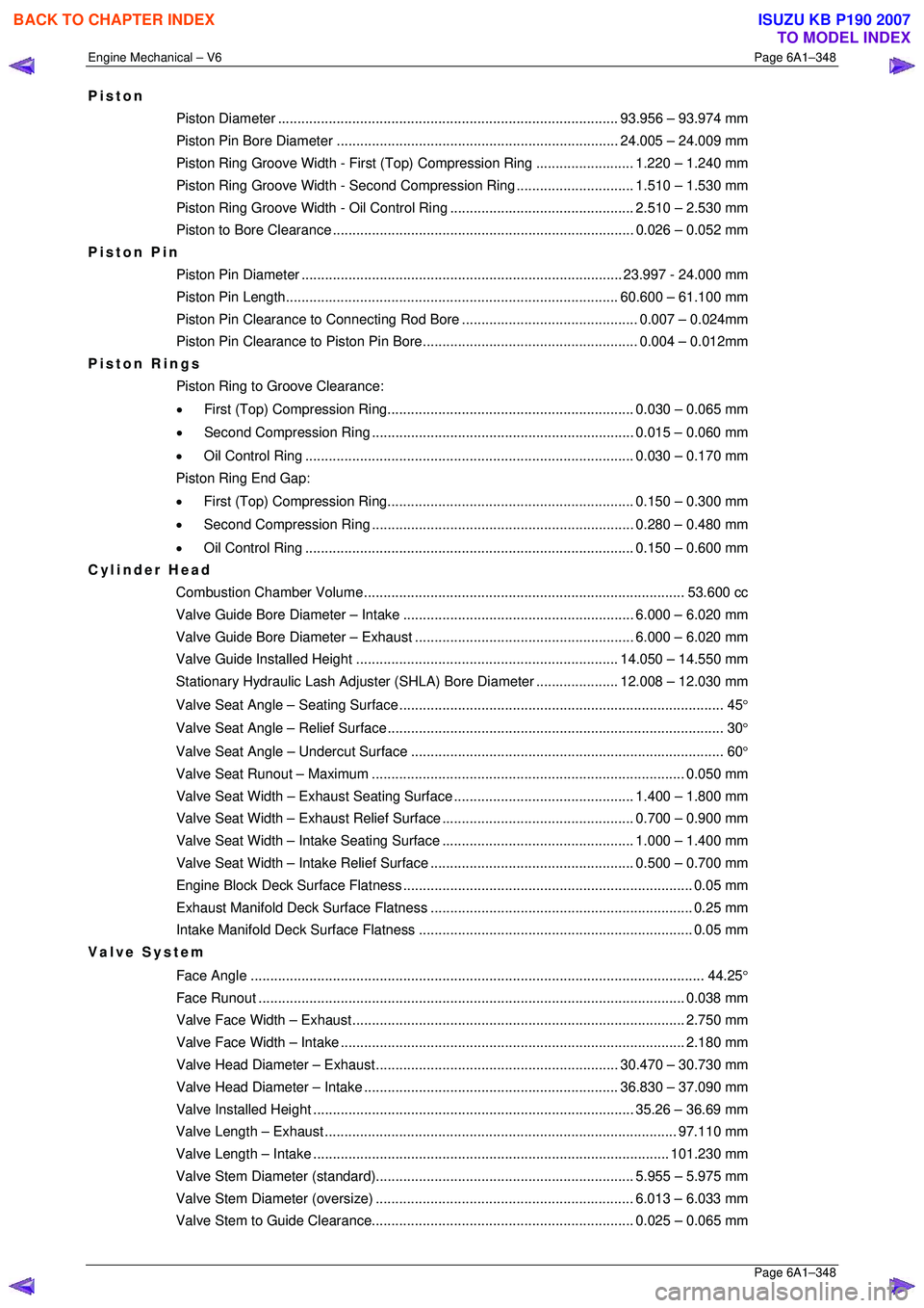
Piston
Piston Diameter ....................................................................................... 93. 956 – 93.974 mm
Piston Pin Bore Diame ter ........................................................................ 24.005 – 24.009 mm
Piston Ring Groove Width - First (Top) Compression Ring ......................... 1.220 – 1.240 mm
Piston Ring Groove Width - Second Compression Ring.............................. 1. 510 – 1.530 mm
Piston Ring Groove Width - Oil Control Ring ............................................... 2. 510 – 2.530 mm
Piston to Bore Clear ance ............................................................................. 0.026 – 0.052 mm
Piston Pin
Piston Pin Diamet er .................................................................................. 23.997 - 24.000 mm
Piston Pin Length ..................................................................................... 60. 600 – 61.100 mm
Piston Pin Clearance to Connec ting Rod Bore............................................. 0. 007 – 0.024mm
Piston Pin Clearance to Pist on Pin Bore....................................................... 0. 004 – 0.012mm
Piston Rings
Piston Ring to Groove Clearance:
• First (Top) Compression Ring............................................................... 0. 030 – 0.065 mm
• Second Compression Ring ................................................................... 0.015 – 0.060 mm
• Oil Control Ring .................................................................................... 0. 030 – 0.170 mm
Piston Ring End Gap:
• First (Top) Compression Ring............................................................... 0. 150 – 0.300 mm
• Second Compression Ring ................................................................... 0.280 – 0.480 mm
• Oil Control Ring .................................................................................... 0. 150 – 0.600 mm
Cylinder Head
Combustion Chambe r Volume.................................................................................. 53. 600 cc
Valve Guide Bore Diameter – Intake ........................................................... 6.000 – 6.020 mm
Valve Guide Bore Diameter – Exhaust ........................................................ 6.000 – 6.020 mm
Valve Guide Installed Height................................................................... 14. 050 – 14.550 mm
Stationary Hydraulic Lash Adjuster (S HLA) Bore Diameter .....................12.008 – 12.030 mm
Valve Seat Angle – Seating Surface ................................................................................... 45 °
Valve Seat Angle – Relief Surface...................................................................................... 30 °
Valve Seat Angle – Un dercut Surface ................................................................................ 60 °
Valve Seat Runout – Maximum................................................................................ 0. 050 mm
Valve Seat Width – Exhaust S eating Surface.............................................. 1. 400 – 1.800 mm
Valve Seat Width – Exhaust Re lief Surface................................................. 0. 700 – 0.900 mm
Valve Seat Width – Intake Se ating Surface................................................. 1. 000 – 1.400 mm
Valve Seat Width – Intake Relief Surface.................................................... 0. 500 – 0.700 mm
Engine Block Deck Surf ace Flatness .......................................................................... 0. 05 mm
Exhaust Manifold Deck Su rface Flatness ................................................................... 0. 25 mm
Intake Manifold Deck Su rface Flatness ...................................................................... 0. 05 mm
Valve System
Face Angle .................................................................................................................... 4 4.25°
Face Run out ............................................................................................................. 0.038 mm
Valve Face Width – Exhaust..................................................................................... 2. 750 mm
Valve Face Width – Intake........................................................................................ 2. 180 mm
Valve Head Diameter – Ex haust .............................................................. 30.470 – 30.730 mm
Valve Head Diameter – Intake ................................................................. 36. 830 – 37.090 mm
Valve Installed He ight .................................................................................. 35.26 – 36.69 mm
Valve Length – Exhaust.......................................................................................... 97. 110 mm
Valve Length – Intake ........................................................................................... 101.230 mm
Valve Stem Diameter (s tandard).................................................................. 5. 955 – 5.975 mm
Valve Stem Diameter (o versize).................................................................. 6.013 – 6.033 mm
Valve Stem to Guide Clearance................................................................... 0. 025 – 0.065 mm
BACK TO CHAPTER INDEX
TO MODEL INDEX
ISUZU KB P190 2007
Page 3199 of 6020
Engine Cooling – V6 Engine Page 6B1–64
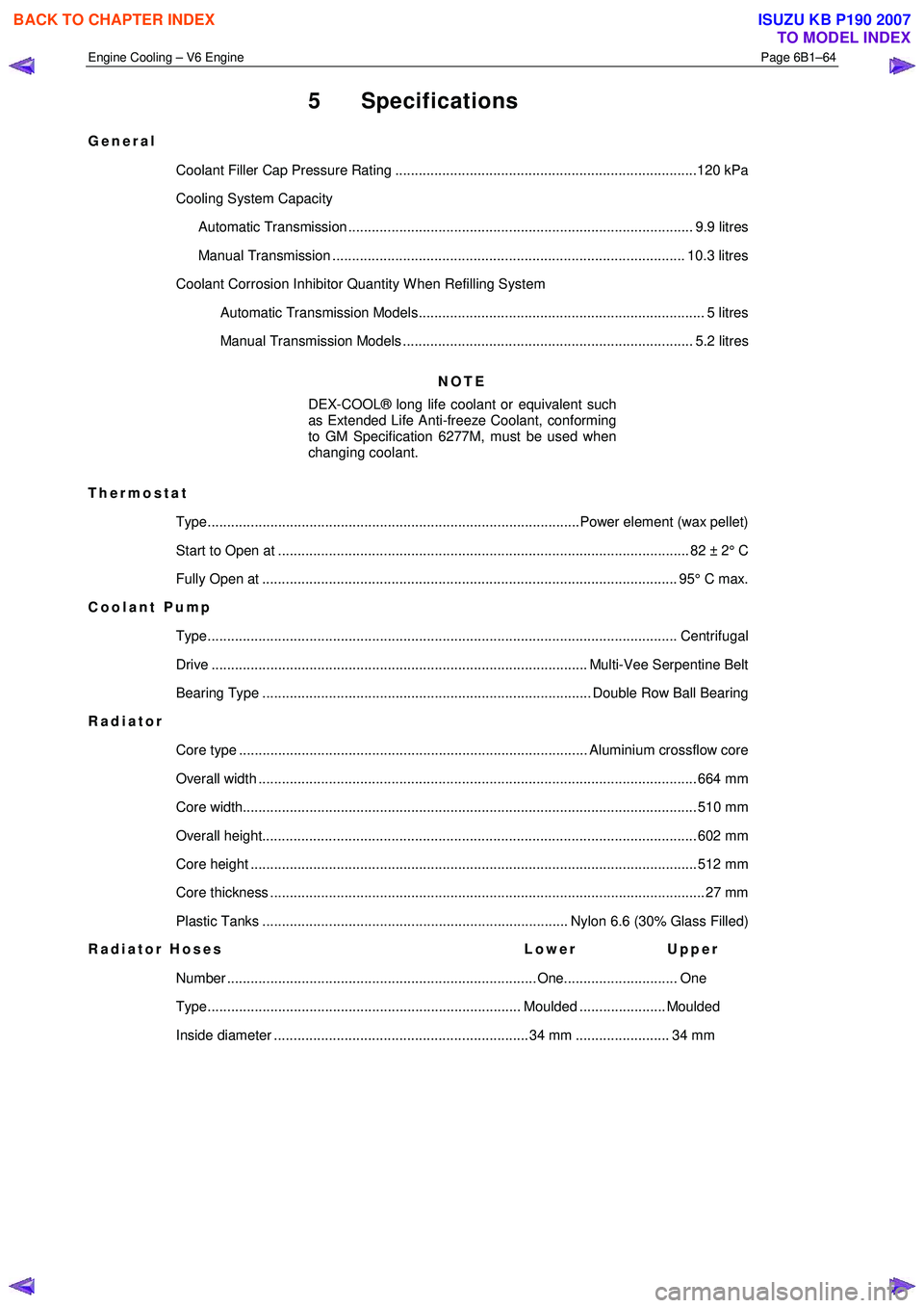
5 Specifications
General
Coolant Filler Cap Pressure Rating .............................................................................120 kPa
Cooling System Capacity
Automatic Transmission ........................................................................................ 9.9 litres
Manual Transmission .......................................................................................... 10.3 litres
Coolant Corrosion Inhibitor Quantity W hen Refilling System Automatic Transmission Models......................................................................... 5 litres
Manual Transmission Models .......................................................................... 5.2 litres
NOTE
DEX-COOL® long life coolant or equivalent such
as Extended Life Anti-freeze Coolant, conforming
to GM Specification 6277M, must be used when
changing coolant.
Thermostat Type...............................................................................................Power element (wax pellet)
Start to Open at ......................................................................................................... 82 ± 2 ° C
Fully Open at .......................................................................................................... 95° C ma x.
Coolant Pump
Type........................................................................................................................ Cen trifugal
Drive ................................................................................................ Multi-Vee Serpentine Belt
Bearing Type .................................................................................... Double Row Ball Bearing
Radiator
Core type ......................................................................................... Aluminium crossflow core
Overall width ................................................................................................................ 66 4 mm
Core width.................................................................................................................... 5 10 mm
Overall height............................................................................................................... 60 2 mm
Core height .................................................................................................................. 51 2 mm
Core thickness ............................................................................................................... 27 mm
Plastic Tanks .............................................................................. Nylon 6.6 (30% Glass Filled)
Radiator Hoses Lower Upper
Number ............................................................................... One............................. One
Type................................................................................ Moulded ...................... Moulded
Inside diameter ................................................................. 34 mm ........................ 34 mm
BACK TO CHAPTER INDEX
TO MODEL INDEX
ISUZU KB P190 2007
Page 3252 of 6020
Engine Management – V6 – General Information Page 6C1-1–10
Fuel Injection System
Each cylinder of the V6 engine is fitted with one fuel injector. The engine control relay applies ignition positive voltage to
the fuel injector ignition circuit. The ECM controls the operation of the fuel injectors by applying a pulse width modulated
(PW M) ground to the fuel injector control circuit to control each fuel injector on-time.
W hile the engine is running, the ECM constantly monitors the various inputs and recalculates the appropriate on-time for
each injector. The calculation is based on the following:
• The injector flow rate,
• Mass of fuel passed by the energised injector per unit of time,
• The desired air / fuel ratio, and
• Actual air mass in each cylinder.
The ECM calculates the duration of the fuel injector on-time to deliver the correct amount of fuel for optimum drivability
and emission control. The period of time the fuel injector is energised is called the injector on-time and is measured in
milliseconds (thousandths of a second).
The V6 engine uses the sequential fuel injection system. Each fuel injector is energised individually at the correct
moment during its firing stroke as the cylinder’s intake valves are closing to provide enough time for the fuel to atomise
completely and mix with the intake air.
Short Term Fuel Trim
The short term fuel trim (STFT) represents the duration of the fuel injector on-time as calculated by the ECM, while the
ECM is in Closed Loop mode. The STFT allows the ECM to calculate the fuel injector on-time based on the heated
oxygen sensor (HO2S) signal input to the ECM. Therefore, the STFT is disabled when the ECM is in Open Loop mode.
• If the air / fuel mixture in the exhaust is balanced (lambda = 1) or when the STFT is disabled, the STFT value is 0%.
• W hen the HO2S sends an input signal to the ECM indicating the air / fuel mixture is rich, the STFT will be less than
0%, which indicates the ECM is decreasing the fuel injector on-time to reduce the amount of fuel in the air / fuel
mixture.
• W hen the HO2S sends an input signal to the ECM indicating the air / fuel mixture is lean, the STFT will be greater
than 0%, which indicates the ECM is increasing the fuel injector on-time to increase the amount of fuel in the air /
fuel mixture.
The percentage values of the STFT range from –25% to +25% and are directly proportional to the duration of the fuel
injector on-time.
Long Term Fuel Trim
The ECM stores the long term fuel trim (LTFT) in its memory to adjust the fuel injector on-time according to the long term
changes or deterioration in the engine components. The normal LTFT value is 0%.
The following describes the LTFT operation when the engine air filter is dirty that causes a restricted intake airflow fault
condition:
1 The HO2S sends an input signal to the ECM the air / fuel mixture is rich because of the reduced airflow. The STFT may reduce to a value of –10%, which decreases the fuel injector on-time to reduce the amount of fuel in the air /
fuel mixture supplied to the engine.
W ithout the use of the LTFT, the restricted airflow caused by the dirty air filter may reduce the STFT value to –10% until the air filter is replaced. This will decrease the range of negative adjustment available to the STFT to
compensate for other factors.
2 W hen the ECM detects the STFT has remained at –10% for a specific period, the ECM switches to the LTFT. The LTFT adjusts the duration of the fuel injector on-time until the air / fuel mixture in the exhaust is balanced (lambda =
1) and the STFT value returns to 0%.
3 The ECM stores this Long Term FT value in its memory, which is used to calculate the base fuel injector on-time.
The percentage values of the Long Term FT range from –100% to +100%. If the ECM detects the LTFT values are
outside the specified percentage range for a predetermined period, the ECM will set a Diagnostic Trouble Code and
switch to Open Loop mode.
BACK TO CHAPTER INDEX
TO MODEL INDEX
ISUZU KB P190 2007
Page 3253 of 6020
Engine Management – V6 – General Information Page 6C1-1–11
3.2 Air / Fuel Control System
The engine control module (ECM) controls the amount of air and fuel delivered into each of the engine cylinders. Based
on the various ECM inputs, the ECM switches to the following air / fuel control system mode to provide the optimum air /
fuel ratio under all engine operating conditions.
Starting Mode
W hen the ignition switch is moved to the START position and the engine begins to turn, a prime pulse may be injected to
speed starting. As soon as the ECM receives an input signal from the camshaft position (CMP) and crankshaft position
(CKP) sensor and determines which cylinder is in the firing stroke, the ECM applies a pulse width modulated (PW M)
ground to the injector control circuit. The ECM monitors mass air flow, intake air temperature, engine coolant
temperature, and throttle position to determine the required fuel injector on-time required for starting the engine.
Run Mode
The engine switches to run mode when the engine speed reaches 480 rpm after being started. The run mode has two
sub-modes called Open Loop and Closed Loop.
Open Loop Mode
The heated oxygen sensor (HO2S) does not produce a usable signal voltage output until it reaches operating
temperature. Therefore, while the HO2S is below its operating temperature, the ECM switches to open loop mode.
In open loop, the ECM ignores the signals from the HO2S and calculates the required injector pulse width based
primarily on inputs from the mass air flow (MAF), intake air temperature (IAT), and engine coolant temperature sensors.
The system will stay in the open loop mode until the HO2S produce a usable output.
Closed Loop Mode
Once the HO2S reaches operating temperature and starts producing its own signal voltage output, the ECM switches to
the closed loop mode.
In closed loop mode, the ECM initially calculates injector pulse width based on the same sensors used in open loop, and
additionally the ECM uses the oxygen sensor signals to modify and fine tune the fuel pulse width calculations to precisely
maintain the ideal 14.7 to 1 air / fuel ratio.
Acceleration Mode
The ECM monitors and calculates input signals from the accelerator pedal position (APP) and MAF sensor signals to
determine when the vehicle is being accelerated. If the ECM detects the accelerator pedal is depressed and there is a
demand for the vehicle to accelerate, the ECM switches to acceleration mode. In acceleration mode, the ECM increases
the fuel injector on-time to provide more fuel accordingly.
Deceleration Mode
The ECM monitors and calculates input signals from the APP and MAF sensor signals to determine when the vehicle is
being decelerated. If the ECM detects the vehicle is decelerating, the ECM switches to deceleration mode. In
deceleration mode, the ECM decreases the fuel injector on-time, or disables the fuel injectors for short periods, to reduce
exhaust emissions and improve fuel economy.
Fuel Shut-off Mode
To protect the engine from damage or to improve the vehicle's driveability, the ECM switches to the fuel shut-off mode. In
fuel shut-off mode, the ECM performs the following:
• The ECM disables the six fuel injectors under the following conditions:
− Ignition off – to prevent engine dieseling,
− Ignition on but no ignition reference signal – prevents flooding or backfiring,
− At high engine speed – greater than the red line (rev limiter),
− At high vehicle speed – greater than the rated tire speed (vehicle speed limiter), or
− Extended high speed closed throttle coast-down – reduces engine emissions and increases engine braking.
• The ECM selectively disables the appropriate number of fuel injectors when torque management has been enabled.
BACK TO CHAPTER INDEX
TO MODEL INDEX
ISUZU KB P190 2007
Page 3257 of 6020
Engine Management – V6 – General Information Page 6C1-1–15
W hen the cruise control ON-OFF switch, located on the right hand side of the dash panel, is pressed, the PIM, on
receiving the input from the switch, turns on the cruise ON-OFF switch warning lamp to inform the user that the cruise
control has been engaged.
W hen the cruise control switch assembly is pressed to SET/COAST, the PIM on receiving the input, sends a signal via
the serial data bus to the ECM. Providing the pre-conditions for cruise control operation have been met, the ECM
activates cruise control and commands the PIM to turn on the instrument cluster cruise set warning lamp, to inform the
user that cruise control is active. The ECM receives all the various inputs required to maintain the correct speed and then
controls the throttle plate depending on the load on the engine (ascending or descending hills, etc).
The cruise control is deactivated by either pressing the brake pedal, clutch pedal, cruise CANCEL or by the cruise control
ON-OFF button. In each of these instances, the ECM receives an input when any of these switches are activated. For
further information on the cruise control system, refer to 8C Cruise Control – HFV6.
3.7 Brake Torque Management
Brake torque management places limits on engine torque when the brakes are applied, regardless of the accelerator
pedal position (APP). The conditions under which brake torque management occur are as follows:
• The accelerator has been depressed before the brakes are applied,
• The brakes are applied and the ECM receives an input from the stop lamp switch,
• Vehicle speed is greater than 5 km/h,
• Engine speed is greater than 1200 rpm and
• Conditions exist for greater than 2.5 seconds.
W hen brake torque management has been implemented, the torque is reduced by altering the throttle plate opening by
25%. The ECM will monitor the rate at which the vehicle is slowing and adjust the throttle plate opening accordingly.
3.8 Emission Control Systems
Evaporative Emission Control System
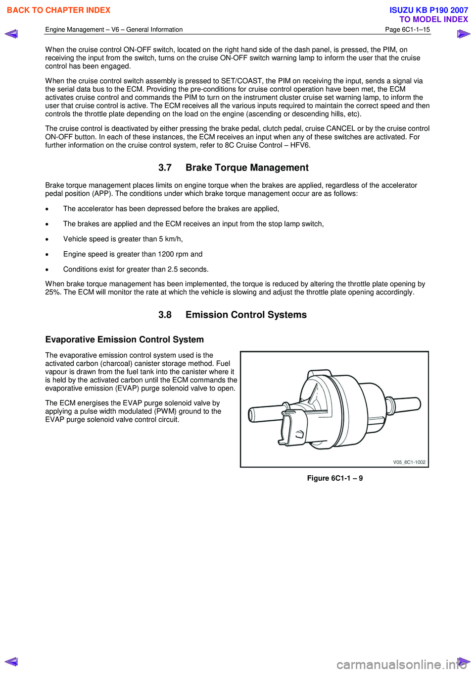
The evaporative emission control system used is the
activated carbon (charcoal) canister storage method. Fuel
vapour is drawn from the fuel tank into the canister where it
is held by the activated carbon until the ECM commands the
evaporative emission (EVAP) purge solenoid valve to open.
The ECM energises the EVAP purge solenoid valve by
applying a pulse width modulated (PW M) ground to the
EVAP purge solenoid valve control circuit.
Figure 6C1-1 – 9
BACK TO CHAPTER INDEX
TO MODEL INDEX
ISUZU KB P190 2007
Page 3265 of 6020
Engine Management – V6 – General Information Page 6C1-1–23
4.8 Engine Coolant Temperature Sensor
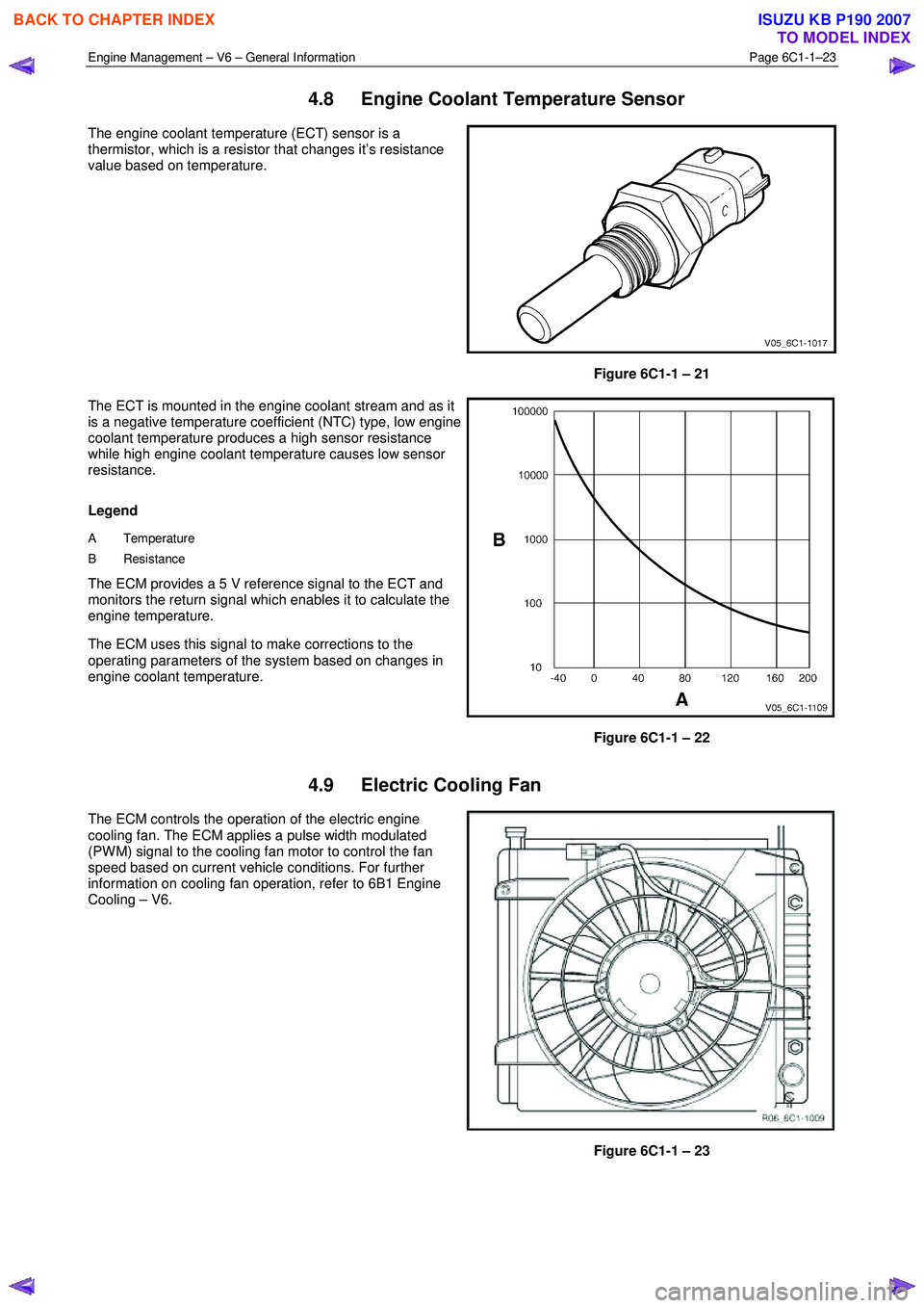
The engine coolant temperature (ECT) sensor is a
thermistor, which is a resistor that changes it’s resistance
value based on temperature.
Figure 6C1-1 – 21
The ECT is mounted in the engine coolant stream and as it
is a negative temperature coefficient (NTC) type, low engine
coolant temperature produces a high sensor resistance
while high engine coolant temperature causes low sensor
resistance.
Legend
A Temperature
B Resistance
The ECM provides a 5 V reference signal to the ECT and
monitors the return signal which enables it to calculate the
engine temperature.
The ECM uses this signal to make corrections to the
operating parameters of the system based on changes in
engine coolant temperature.
Figure 6C1-1 – 22
4.9 Electric Cooling Fan
The ECM controls the operation of the electric engine
cooling fan. The ECM applies a pulse width modulated
(PW M) signal to the cooling fan motor to control the fan
speed based on current vehicle conditions. For further
information on cooling fan operation, refer to 6B1 Engine
Cooling – V6.
Figure 6C1-1 – 23
BACK TO CHAPTER INDEX
TO MODEL INDEX
ISUZU KB P190 2007
Page 3269 of 6020
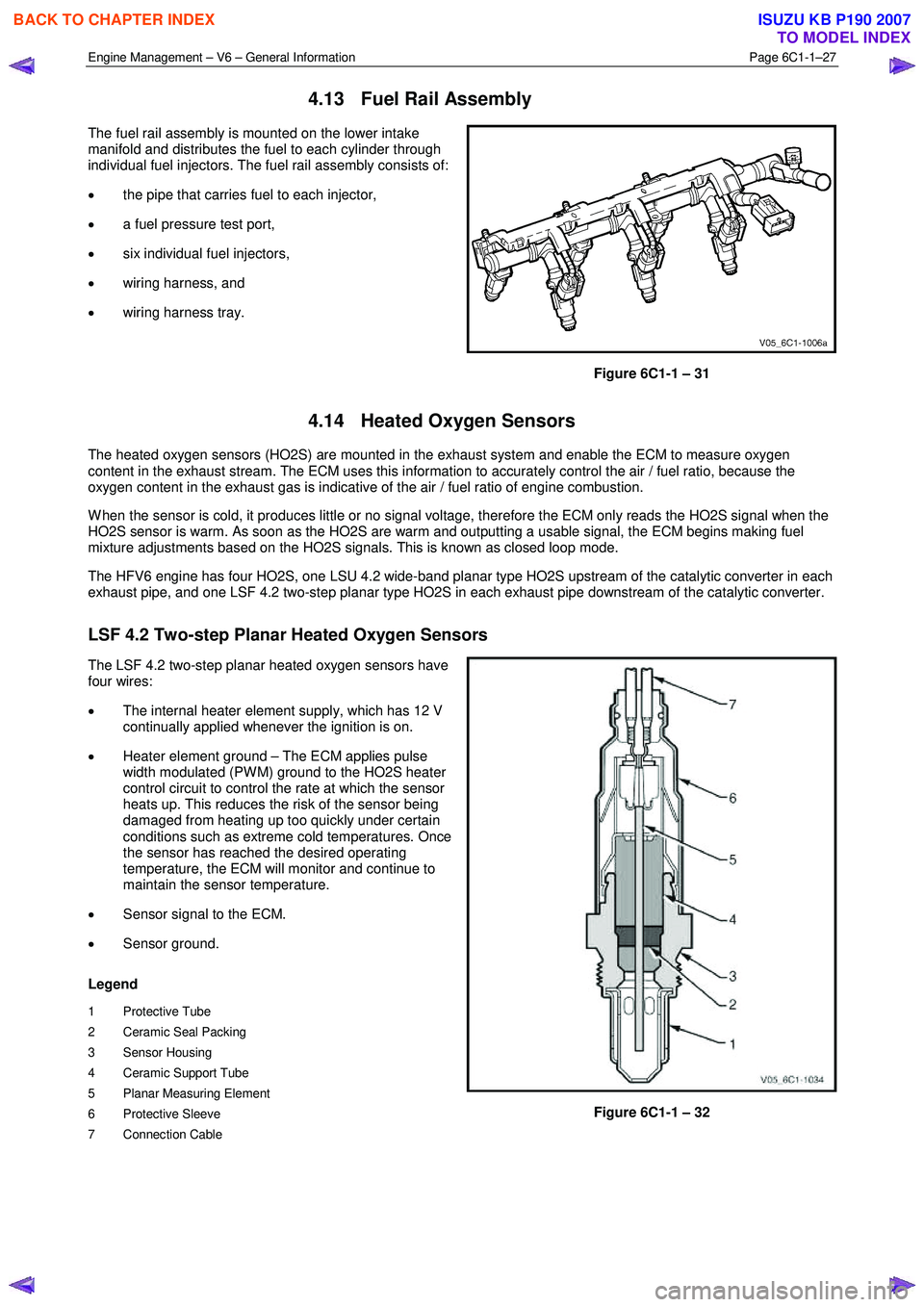
Engine Management – V6 – General Information Page 6C1-1–27
4.13 Fuel Rail Assembly
The fuel rail assembly is mounted on the lower intake
manifold and distributes the fuel to each cylinder through
individual fuel injectors. The fuel rail assembly consists of:
• the pipe that carries fuel to each injector,
• a fuel pressure test port,
• six individual fuel injectors,
• wiring harness, and
• wiring harness tray.
Figure 6C1-1 – 31
4.14 Heated Oxygen Sensors
The heated oxygen sensors (HO2S) are mounted in the exhaust system and enable the ECM to measure oxygen
content in the exhaust stream. The ECM uses this information to accurately control the air / fuel ratio, because the
oxygen content in the exhaust gas is indicative of the air / fuel ratio of engine combustion.
W hen the sensor is cold, it produces little or no signal voltage, therefore the ECM only reads the HO2S signal when the
HO2S sensor is warm. As soon as the HO2S are warm and outputting a usable signal, the ECM begins making fuel
mixture adjustments based on the HO2S signals. This is known as closed loop mode.
The HFV6 engine has four HO2S, one LSU 4.2 wide-band planar type HO2S upstream of the catalytic converter in each
exhaust pipe, and one LSF 4.2 two-step planar type HO2S in each exhaust pipe downstream of the catalytic converter.
LSF 4.2 Two-step Planar Heated Oxygen Sensors
The LSF 4.2 two-step planar heated oxygen sensors have
four wires:
• The internal heater element supply, which has 12 V
continually applied whenever the ignition is on.
• Heater element ground – The ECM applies pulse
width modulated (PW M) ground to the HO2S heater
control circuit to control the rate at which the sensor
heats up. This reduces the risk of the sensor being
damaged from heating up too quickly under certain
conditions such as extreme cold temperatures. Once
the sensor has reached the desired operating
temperature, the ECM will monitor and continue to
maintain the sensor temperature.
• Sensor signal to the ECM.
• Sensor ground.
Legend
1 Protective Tube
2 Ceramic Seal Packing
3 Sensor Housing
4 Ceramic Support Tube
5 Planar Measuring Element
6 Protective Sleeve
7 Connection Cable
Figure 6C1-1 – 32
BACK TO CHAPTER INDEX
TO MODEL INDEX
ISUZU KB P190 2007